Role of photorefractive holographic interferometry in Impact Assessment
Procedure applied to movable cultural heritage
Cedric Thizy
1, D. Derauw
1, Marc P. Georges
1, Eleni Kouloumpi
2, Stephen Hackney
3, Tim
Green
3, Vivi Tornari
41
Centre Spatial de Liège - Université de Liège, Liege Science Park, B-4031 Angleur, Belgium,
e-mail : mgeorges@ulg.ac.be
2
National Gallery - Alexandro Soutzos Museum, 1 Michalacopoulou Street, 11601, Athens,
Greece
3
Tate, Millbank, London SW1P 4RG, UK
4
Foundation for Research and Technology-Hellas/Institute of Electronic Structure and Laser,
Vassilika Vouton, Voutes, 71 110 Heraklion-Crete, Greece
ABSTRACT
Photorefractive holographic interferometry is applied to an Impact Assessment Procedure of movable cultural heritage within the framework of the European project MULTIENCODE. Due to its high resolution capability, the role of this technique is to observe tiny signatures resulting from internal artwork characteristics. Results are presented on two types of representative samples (canvas and panel paintings). We also present an interferogram post-processing technique which allows perfect superposition of interferograms for further comparison.
INTRODUCTION
The use of holographic interferometry and speckle interferometry techniques [1,2] for artwork assessment is not new. A lot of work has been done in demonstration of several such techniques by some european groups. The first evidence was shown by Amadesi et al. [3] who used holographic interferometry to detect debondings in old paintings. Since then different groups have contributed significantly to this field of research. One can cite Paoletti and Spagnolo, whom review paper [4] is a significant summary of their work and work of others, the Oldenburg University [5-7] and finally the Institute of Electronic Structure and Laser of Heraklion (FORTH/IESL) [8,9].
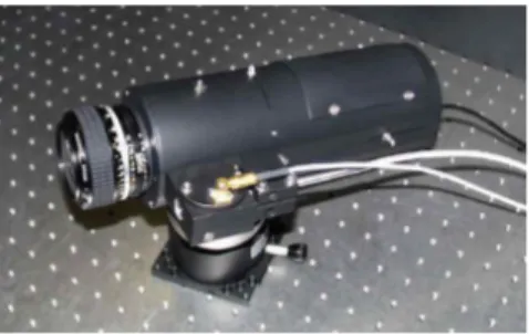
The currently ongoing european project MULTIENCODE ("MULTIfunctional ENCODing system for assessment of movable cultural heritage"), led by FORTH/IESL, aims at going a step further by establishing a new standard Impact Assessment Procedure (IAP) for monitoring of defects of movable artworks, either for conservation purpose (unstable defects) or for authenticity verification (stable defects). Two types of artwork are considered : wooden icons (or panel paintings) and textile canvas paintings. The project axes are the following : (i) investigation of holographic techniques for IAP (electronic speckle pattern interferometry, shearography and photorefractive dynamic holographic interferometry are considered), (ii) develop standardized procedure common for all techniques for optimized observation of defect signatures in interferograms, (iii) develop an encode-decode tool for storage into and retrieval from a defect database related to the artwork, (iv) design and manufacturing of an optimized sensor and finally (v) demonstration of sensor on movable artworks provided by end-user galleries. The Centre Spatial de Liège is concerned by the study and demonstration of photorefractive holographic interferometry with the purpose of high resolution capabilities of the technique together with a high flexibility of use. The instrument used for that purpose is the holographic camera whose development has been presented elsewhere [10,11] and is shown in Figure 1.
Figure 1. Photorefractive holographic camera
In this paper we will review the results obtained within the project on two types of representative artworks (panel and textile canvas paintings). Further we will present a technique of coregistration of images which can constitute a useful step for the IAP.
RESULTS ON CANVAS PAINTINGS
Paintings on textile canvas were manufactured and provided by the Tate and an example is shown in Figure 2(a). Prior to painting, the museum conservators have introduced a series of defects of different types as can be seen on the picture taken prior to painting (Figure 2 (b)). Additionnally to these internal defects, a large circular crack (visible at the eye) is present in the centre of the paintings in Figure 2(a).
Figure 2. (a) Representative sample of painting on textile canvas. A circular crack is barely visible inside the red circle. (b) Artificial defects/inclusions present between the canvas and the paint layer.
Besides the search for internal defects, what was of interest for the Tate conservators is the observation of crack propagation, or the prediction of further crack appearance prior to crack visibility at the eye. Because of the particular nature of the canvas and its mechanical behaviour, different types of stresses have been tested.
Before describing these different stimulations, we had to face the fact that such canvas are naturally vibrating due to the acoustic noise in the lab (noise of the equipments, air movement due to closing doors, etc). Since our holographic camera records the reference hologram during 5 to 10 seconds, such conditions of use on such difficult object often prevent us to have good recording and hence good interferograms.
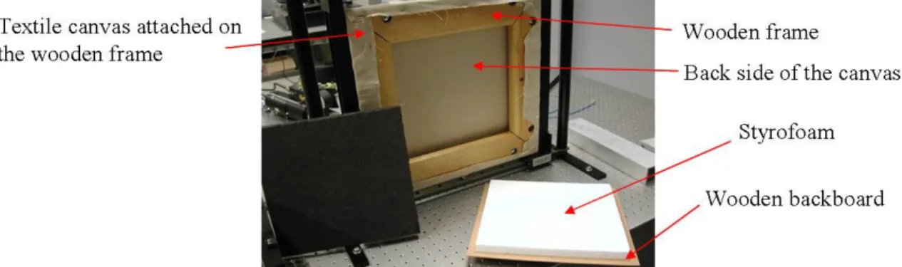
Therefore our first investigations concerned the stabilization of the canvas. For that we considered first a stainless steel plate put in close contact to the back side of the canvas. This gave very good results but was not retained for its bad applicability in practice. Another solution is to use the backboard that comes with the painting during its travel in a special box. This backboard is a wooden plate on which is glued a styrofoam plate of typically 2 cm height and that is close to the back side of the canvas but not directly in contact with it (Figure 3). Experiments showed that the backboard presence was a good solution for stabilization of the painting during hologram recording and that point of the procedure was agreed by the conservators.
Figure 3. Back side of the canvas painting. The different parts of the canvas and the backboard are shown.
The first stimulation of the object is the natural excitation which is an undeterministic combination of temperature changes, Relative Humidity (RH) changes and acoustic noise vibrations. After a reference hologram is recorded, interferograms are observed sequentially at various instants ranging from minutes to tens of minutes. We have to note that between the readouts, the photorefractive crystal does not receive any light in order to not erase the reference hologram. This is possible by an internal shutter placed onboard the device.
Figure 4. Interferograms on canvas painting obtained by natural excitation.
Figure 4(a) shows the interferogram obtained 2 minutes after reference recording. We can see that the central crack yields a clearly circular pattern in the center. Figure 4(b) is taken 6 minutes after reference recording, the fringe pattern is denser but the overall fringe shape is similar. None of the artificial internal defect is clearly visible in the pattern. Natural excitation is an interesting mean to detect the defect signatures of the canvas, for instance the crack can be easily identified by changes in the fringe pattern. The latter is quite complex and if the measurements are repeatable and reproducible, it could be a good fingerprint of the canvas. The problem is precisely the repeatability and reproducibility of the measurement. Indeed, results obtained with a natural excitation are dependent on the environment. Thus if this excitation is to be used, the surrounding environment of the canvas has to be controlled.
Another possibility of excitation was a change of RH [12] by placing silica gel cassettes in the back of the canvas and recording holograms followed by readout some minutes later. We showed that the fringe patterns were extremely complicated and where not related to the defects of the paintings but instead were related to the random presence of silica gel just behind the canvas.
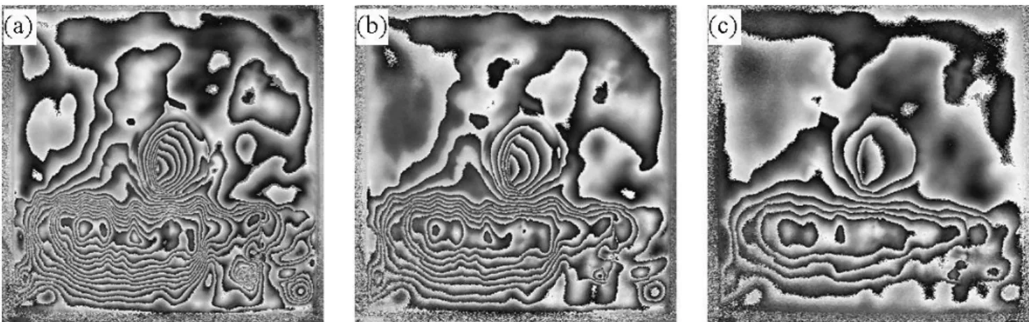
For finding a more controllable way to stimulate the defects, we considered the more classical IR heating that was used for the wooden icons. Here a short heating of 1 s is applied with a 175 W IR lamp at 1 meter in front of the painting. Interferograms are observed some instants after heating has stopped: Figure 5(a), (b) and (c) respectively after 1s, 12s and 34s.
Figure 5. Interferograms obtained by IR heating of the canvas: (a) 1s , (b) 12s and (c) 34s after heating.
The fringe patterns have a shape that is more consistent with those found with natural excitation. Further experiment showed that the under the same circumstances and procedure, the interferograms are reproducible. Therefore this methodology is the one we will keep as a standard.
A more detailed analysis of the fringe pattern yields to conclusion that the higher density in the bottom of the images is due to overpainting (as can be seen in Figure 2(a)) and not to defects. None of the other holographic techniques compared allowed a good view of these defects.
RESULTS ON PANEL PAINTINGS
The other category of artworks considered is that of panel paintings (i.e. substrate is in wood). We received from National Gallery of Athens a series of representative icons recreated in the conservation lab following traditional techniques and containing a typical set of defects that could constitute signatures.
Figure 6(a) shows a schematic sketch of the icon with defects and their location represented. One can see a circular knot with a vertical crack in the middle of the icon. A small nail is present on the upper rigtht corner. Figure 6(b) shows the phase interferogram (after application of phase-shifting) observed after a few seconds heating and relaxation time on the order of 2 minutes. The two main defects (surrounded by dashed lines) give rise to signatures in the fringe pattern. In particular, the crack is seen via a strong change of fringes direction. Figure 6(c) shows the phase map obtained after phase unwrapping of Figure 6(b). An interesting way of showing the defects is by differentiating the unwrapped phase image which allows to obtain a shearographic-like image as displayed here in Figure 6(d) (here a horizontal shear has been applied numerically). Another way to measure and locate precisely defects is to trace horizontal and vertical profiles in the unwrapped phase map, respectively Figure 6(e) and Figure 6(f).
Figure 6. Typical results obtained on wooden icons.
Another example of results obtained by CSL is shown in Figure 7 for unstable defects: original before ageing, after one ageing and after restoration by National Gallery of Athens conservators. The images are interferograms (upper) and post-processed differentiated images (bottom). It is clear that stable defects are present (circled in blue) but after ageing new small defects appear (circled in green). After restoration, the new defects have disappeared. However a new defect appeared and an existing one has increased (density of fringes higher)
Figure 7.Post-processed differentiated interferograms obtained by CSL with DyHI showing unstable defect signatures (circled in green) : left prior to ageing, middle after 1st ageing, right after restoration
COREGISTRATION OF IMAGES FOR COMPARISON
The IAP requires comparing two interferograms, with some differences that are due to signatures variation between the two moments of the interferograms capture. Also it is supposed that the user does not perfectly place the hardware in the same position. Consequently the two images to be compared have some lateral/rotational shifts and/or various zooming factors one to another. Therefore, we shall find a way to render them completely superimposed before any comparison, whatever the comparison algorithm/technique used.
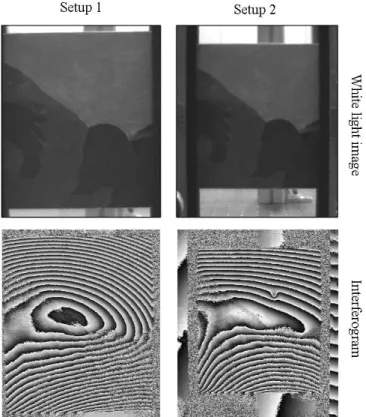
This is shown in Figure 8 where two different set-up of the hardware (here the CSL holographic camera) were deliberately induced: we can see that different zooming factors, lateral shift and rotation of the image have been used. The problem is the following: is it possible to find a transformation of Setup 2 images which make them similar to Setup 1 images. Once this transformation is found, it shall be applied to the interferograms without destroying the phase jumps.
Figure 8. Situation where two interferograms with different signatures and setup have to be compared.
The process for transforming the second interferogram in such a way that it can be perfectly compared to the first one has been tested by CSL on the basis of an existing software that was developed by another group of CSL for Synthetic Aperture Radar applications [13,14].
The first step consists in finding the affine transform between both set-up by an automated process that uses white light images. The second step is the interpolation of the second interferogram using this affine transform. The major point is that the transform is applied to a complex interferogram which is obtained on the basis of the original interferograms. If the transform is applied straight to the intensity interferograms, strong errors appear in the fringe pattern that will generate artefacts in the signatures comparison.
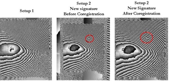
Figure 9 shows the results before and after coregistration has been applied. The left image shows an interferogram obtained with a first setup and no signature appearing. Both other images have been obtained with a new and strongly different setup. Additionally, a defect/signature has been induced in the painting (in red circle). The right image shows the central image after it has been coregistered to the left one with the procedure above described. Various comparison algorithms can be applied now to compare these 2 coregistered images.
Figure 9. Result of application of coregistration to central image for matching the left image.
CONCLUSIONS
Photorefractive holographic interferometry has been used within the frame of the MULTIENCODE project. The high resolution capability of the technique is interesting to capture small signatures of the artwork. The technique experiences some limitations in recording hologram of textile canvas painting. This is due to the fact that the hologram recording time is a few seconds and that during this time the canvas is vibrating too much. Therefore in such cases a canvas stabilization is required. The technique allows easier hologram recording with panel paintings which are naturally more stable.
When a good hologram recording is achieved, the interferogram quality is excellent and close fringes are observed without noise.
This technique showed its interest during the MULTIENCODE project but shall be used in combination with other complementary techniques such as shearography and ESPI which are more immune to external vibration but at the expense of a generally lower interferogram quality.
ACKNOWLEDGEMENTS
This research is supported by the European Union funded MULTIENCODE project (Contract N° SSPI - 6427). The authors would like to thank the other developer partners Dr. Kostas Hatzigiannakis, Yannis Orphanos and Irini Bernikola at IESL, and Dr. Roger Groves and Prof. Wolfgang Osten at the Insitut für Technische Optik (Stuttgart) for collaboration during elaboration of standard protocol, common measurement campaign and fruitful discussions during meetings.
REFERENCES
[1] P.K. Rastogi, Ed., Holographic Interferometry : Principles and Methods, Springer Series in Optical Sciences 68, Springer-Verlag, Berlin (1994)
[2] T. Kreis, Holographic Interferometry : Principles and Methods, Akademie Verlag Series in Optical Metrology 1, Akademie Verlag, Berlin (1996)
[3] S. Amadesi, F. Gori, R. Grella, G. Guattari, "Holographic methods for painting diagnostics", Appl. Opt. 13, p. 2009-2013 (1974)
[4] D. Paoletti and G. Schirripa Spagnolo, "Interferometric methods for artwork diagnostics", Progress in Optics XXXV, 167. Elsevier, Amsterdam (1996)
[5] G. Gülker, H. Helmers, K.D. Hinsch, P. Meinlschmidt, K. Wolff, "Deformation mapping and surface inspection of historical monuments", Opt. Las. Eng. 24, 183-213 (1996)
[6] G. Gülker, K.D. Hinsch, A. Kraft, "Deformation monitoring on ancient terrocota warriors by microscopic TV-holography", Opt. Laser Eng. 36(5), p. 501-513 (2001)
[7] K.D. Hinsch, G. Gülker, "Lasers in art conservation", Physics World November 2001, p. 37-42 (2001) [8] V. Tornari, A. Bonarou, V. Zafiropulos, C. Fotakis, Michaelis Doulgeridis, “Holographic Applications in
evaluation of Defect and Cleaning Procedures”, Journal of Cultural Heritage 1 (0) pp. S325 - S329 (2000) [9] V. Tornari, V. Zafiropulos, A. Bonarou, N. A. Vainos, and C. Fotakis, “ Modern technology in artwork
conservation: A laser based approach for process control and evaluation”, Journal of Optics and Lasers in Engineering, vol. 34, pp 309-326 (2000)
[10] M. Georges, V. Scauflaire, Ph. Lemaire, "Compact and portable holographic camera using photorefractive crystals. Applications in various metrological problems", Appl. Phys. B 72, 761-765 (2001)
[11] Ph.C. Lemaire and M.P. Georges, "Dynamic holographic interferometry : devices and applications" in Photorefractive Materials and Their Applications 3, P. Günter and J-P. Huignard, eds, Springer Series in Optical Sciences Vol 115, p.223-251 (2007)
[12] C. Thizy, M.P. Georges, M. Doulgeridis, E. Kouloumpi, T. Green, S. Hackney, V. Tornari, "Role of dynamic holography with photorefractive crystals in a multi-functional sensor for the detection of signature features in movable cultural heritage", Proc. SPIE Vol 6618 on O3A : Optics for Arts, Architecture and Archeology, Paper 6618-28 (2007)
[13] D. Derauw, "Development of an interferometric SAR processor", Proc. SPIE 2584 on Synthetic Aperture Radar and Passive Microwave Sensing, p. 376-383 (1995)
[14] D. Derauw, S. Roose, "Co-registration and complex interpolation", Proc. SPIE 2584 on Synthetic Aperture Radar and Passive Microwave Sensing, p. 326-331 (1995)