O
pen
A
rchive
T
OULOUSE
A
rchive
O
uverte (
OATAO
)
OATAO is an open access repository that collects the work of Toulouse researchers and
makes it freely available over the web where possible.
This is an author-deposited version published in:
http://oatao.univ-toulouse.fr/
Eprints ID : 17425
To link to this article :
DOI:10.1109/TIE.2012.2188870
URL :
http://dx.doi.org/10.1109/TIE.2012.2188870
To cite this version :
Baumann, Cédric and Piquet, Hubert and Roboam, Xavier and Bru,
Eric A Mixed Function for Actuation and Power Flow Control in
Embedded Networks. (2012) IEEE Transactions on Industrial
Electronics, vol. 59 (n° 9). pp. 3596-3603. ISSN 0278-0046
Any correspondence concerning this service should be sent to the repository
administrator:
[email protected]
A Mixed Function for Actuation and Power Flow
Control in Embedded Networks
Cédric Baumann, Hubert Piquet, Xavier Roboam, Member, IEEE, and Eric Bru
Abstract—This paper proposes an original association of a three-phase electrical machine, here a permanent-magnet syn-chronous motor (PMSM) fed by two inverters, which allows to combine two different functions: actuation and power transfers between two DC buses which supply the inverters. The considered AC machine is an open-end winding PMSM allowing the connec-tion of two inverters supplied by two different DC buses inside a high-voltage DC network. The control part of this system uses the Park’s theory not only to drive the actuator in motor as well as in generator operating modes but also to control the energy transfer from one DC bus to the other. The concept, mixing two main functions, is named MAPFC, for “mixed actuation and power flow control.” It has been particularly developed for aeronautic applications even if other application fields could be targeted. The complete modeling and operation of the system are described. Simulation studies and experimental results are presented, which are validating the proposed concepts.
Index Terms—Actuation, aeronautics, embedded networks, homopolar current, high-voltage DC (HVDC), Park’s reference frame, power flow control.
I. INTRODUCTION
T
HE aeronautic domain is undergoing deep changes re-garding electricity applications. Indeed, power generation, distribution, and management issues are critical in order to meet the requirements related to the environment—safety, mass, and volume. Since the advent of the concept of “more electrical aircraft,” electric power is used to supply an increasing number of embedded equipment [1]–[3]. As a legacy of choices made in the 1960s, AC networks are used to deliver the highest per-centage of this electric power, with constant frequency (115 V, 400 Hz) or, more recently, variable frequency (115 V, 360–800 Hz). A recent evolution consists in using a 230-V AC (variableC. Baumann is with Airbus Operations S.A.S., 31060 Toulouse, France (e-mail: [email protected]).
H. Piquet and E. Bru are with the Laboratoire Plasma et Conversion d’Energie, École Nationale Supérieure d’Électronique, d’Électrotechnique, d’Informatique, d’Hydraulique et des Télécommunications, Institut National Polytechnique de Toulouse–Université Paul Sabatier–Centre National de la Recherche Scientifique, Université de Toulouse, 31071 Toulouse, France (e-mail: [email protected]; [email protected]).
X. Roboam is with the Laboratory of Electrotechnics and Indus-trial Electronics (Unite Mixte de Recherche), Ecole Nationale Supérieure d’Electrotechnique, d’Electronique, d’Informatique, d’Hydraulique et des Télécommunications, Institut National Polytechnique de Toulouse/Centre National de la Recherche Scientifique, 31071 Toulouse, France (e-mail: xavier. [email protected]).
Color versions of one or more of the figures in this paper are available online at http://ieeexplore.ieee.org.
Digital Object Identifier 10.1109/TIE.2012.2188870
frequency) distribution network in order to increase the amount of electrical power available.
However, this voltage can be used to generate a high-voltage DC (HVDC) network [4], [5]. Indeed, a significant percentage of the embedded equipment includes a rectification and filtering input block, whose mass—a critical criterion for aerospace applications—can be spared if the DC voltage power is dis-tributed. Additionally, high-power rectification units can be optimized to reduce the harmonic distortion on the AC network [6], [11]; with this solution, one can expect globally better results than with individual simple rectifiers included in each AC supplied equipment.
While increasing the power/weight ratio by decreasing wiring and deleting local AC/DC converters, HVDC distribu-tion topologies, as well as AC networks, are facing quality or stability issues [7]–[10].
The stability problem is commonly encountered when a constant power load is connected to a regulated DC source [12]. Indeed, the association of those elements through a load input filter can lead to unstabilizing the distribution [13], [14]. Some solutions to solve this problem are available, taking into account the regulation laws of the constant power loads [15]–[18].
Quality of the distributed DC voltage is an issue which is addressed by the standards describing the expected harmonic and transient behavior of the voltage, as well as power avail-ability, even in case of a loss of the generator supplying a power channel. In this last case, the power needs are satisfied by installing an energy transfer from a safe power channel to the one whose generator is out of order.
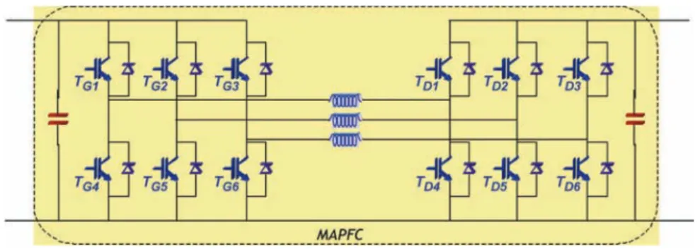
The “mixed actuation and power flow control” (MAPFC) configuration proposed in this paper is able to contribute to the HVDC voltage quality: As will be detailed, it introduces new possible power transfers which can be used to contribute posi-tively to the two last items (transient behavior and availability). In the same time, it satisfies mechanical needs, as the proposed structure is basically a mechanical drive. Indeed, as can be seen in Fig. 1, the windings of an open-ended AC machine are connected between two different DC buses through two voltage source inverters.
This drive-derived structure will be shown to be helpful in managing power in HVDC networks—controlling or balancing power from one bus to the other. Those three cascaded elements are denominated as “MAPFC.” This structure has been pro-posed in other systems to meet other requirements—like hybrid vehicles with energy storage [19], [22], [23]—or with other kind of machines [20].
Considering the AC machine, stator voltages are twice the ones delivered by one inverter; an adapted dimensioning of
Fig. 1. Synoptic of the MAPFC.
the latter has to be done. In this paper, a permanent-magnet synchronous motor (PMSM) is considered, but the principle re-mains valid as well when synchronous or asynchronous motors are used [19], [20].
The use of the Park’s theory helps in decoupling the control of the two mixed functions [26], [27]. A theoretical study of the MAPFC is developed, combining the system modeling and the control method chosen to drive the system. The system is then simulated in many operating cases, and those simulations are confronted with experimental results on a 10-kW MAPFC connected to a reduced power network representative of an aeronautic HVDC network.
II. OPERATINGPRINCIPLES A. Device Modeling
A description of the MAPFC structure is shown in Fig. 1. A three-phase AC machine being part of the MAPFC, it is relatively common to use a Park’s decomposition in order to study the system [7]. The equation set (1) presents the voltage equations of the PMSM in a Park’s reference frame (dqh) related to the rotor [8], the d-axis being associated with the magnetic field of the magnet. Equation (2) gives the different flux expressions in this frame
Ud= Rs· id+dΦdtd − ω · Φq Uq = Rs· iq+ dΦq dt + ω · Φd Uh= Rs· ih+dΦdth (1)
withRs being the stator resistance and ω being the electrical
angular rotation speed.
Note that the voltages considered in (1) are the open-ended stator winding voltages. The fluxes in the (dqh) frame are defined as presented in Φd Φq Φh = Ld 0 0 0 Lq 0 0 0 Lh . id iq ih + Φm 0 0 (2)
where Ld,q,his defined in (3) in the case of a nonsalient pole
machine,Φmis the magnet flux magnitude
Ld= Lq = Ls− Ms Lh= Ls+ 2 · Ms Ls= Lsp+ Lsσ Ms= Lsp· cos µ 2π 3 ¶ = −Lsp 2 . (3)
A modeling of the PMSM machine in the(abc) frame allows the flux expressions to be defined as in (4); a sinusoidal space distribution of the magnetic flux is considered
Φa Φb Φc = La Mab Mac Mba Lb Mbc Mca Mcb Lc · ia ib ic +Φm· cos(θ) cos¡θ−2π3 ¢ cos¡θ−4π3 ¢ . (4) The system is considered to be balanced in order to simplify those relations as stated in
La= Lb= Lc= Ls
Mab= Mba= Mac= Mca= Mbc= Mcb= Ms. (5)
These relations lead to the relationships and the quantities associated with the(dqh) frame, as shown in
Φd Φq Φh = Ls− Ms 0 0 0 Ls− Ms 0 0 0 Ls+ 2 · Ms . id iq ih + Φm 0 0 (6) where Ls is the total inductance of one stator phase and Ms
represents the mutual inductance between two stator windings. It is possible to consider a leakage inductance Lsσ
represent-ing magnetic leakage in the machine stator. As a result, a self-inductance Lspis also added in the system modeling.
Thus, the inductances in the Park’s reference frame are expressed as follows:
Ld= Lq=
3
2Lsp+ Lsσ
Lh= Lsσ. (7)
At this step, the definition of Lh requires an interpretation.
Indeed, (7) defines the homopolar inductance as the stator leakage one. This may have consequences on the machine sizing, as this inductance will have to be chosen in order to allow the homopolar current control, which is not a classical issue. As a result, minimizing the leakage inductance will not be a key factor for sizing the electromagnetic parts.
Regarding the electromechanical torqueΓmof a PMSM
ma-chine with no saliency as expressed in (8), the homopolar axis does not have any impact on the torque. Thus, both functions (actuation and power flow control) can be seen as decoupled
Γm= Φd· id− Φq· iq= Φm· iq. (8)
As the magnet flux is oriented along the d-axis, the torque expression is simplified and is classically only depending on the q-axis current and on the magnet flux.
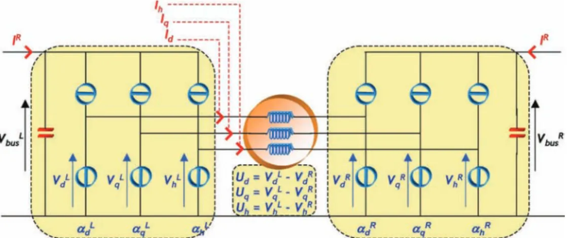
Fig. 2. Electric model of the MAPFC in the Park’s reference frame.
Fig. 3. Control architecture of the MAPFC system.
In order to complete the modeling of the MAPFC, the Park’s differential voltages relatively to the left and right duty cycles also described in the Park’s frame are displayed in
Ud = αLd · VbusL − αRd · VbusR Uq= αLq · VbusL − αRq · VbusR Uh= αLh · VbusL − αRh · VbusR (9) with αL,Rd αL,R q αL,Rh = [Park] · αL,R a αL,Rb αL,Rc
where[Park] represents the Park’s transformation matrix. To determine the current relations, we use the power balance between AC and DC sides of each inverter
½ IL= αL d · id+ αLq · iq+ αLh· ih IR = −¡αR d · id+ αRq · iq+ αRh · ih ¢ (10)
where IL,R denotes, respectively, the left and right inverter
currents on the DC side.
An electric equivalent model in the Park’s frame is shown in Fig. 2.
B. Control Method
The complete modeling of the MAPFC reveals that the currents can be controlled [1] using six duty cycles defined in the Park’s frame(αL,Rd,q,h,). The whole control architecture of the
system is shown in Fig. 3. In order to define the six duty cycles, a strategy is created in each current regulation.
On the d-axis, the current reference is kept to zero. This allows operating with a maximized torque over rms current ratio. The d-axis current loop computes the Udvoltage that has
to be applied on the d-axis across the windings. It should be noted that, when the voltages(Udand Uq) across the windings
are set by the current controllers, one degree of freedom for each axis remains free, as the line voltages (VL
d,q and V R d,q)
have to be determined. Thus, the strategy can be completed by adding (11) and (12) which define the voltages delivered by the two inverters. The d-axis line voltages are chosen to be balanced
½ VL d = Ud 2 VR d = − Ud 2 . (11) Regarding the strategy chosen in the d-axis, the q-axis cur-rent is critical to control the actuator function. In order to ex-ploit the existent remaining degree of freedom, we have chosen
Fig. 4. Power balance between the two inverters: Control architecture of the MAPFC system.
to introduce the possibility to unbalance the actuation power from one side to the other. In this scope, an additional quantity Xactfollowing the law described in Fig. 4 is introduced.
The normal case corresponds to a 50% value of Xactwhere
each inverter supplies the machine with the same power. In an unbalanced case, Xact= 0.3, for instance, the left inverter
supplies 30% of the total amount of actuation power, whereas the right inverter supplies 70%. Equation (12) summarizes the expression of q-axis voltages
½ VL
q = Uq· Xact
VR
q = Uq(Xact− 1).
(12) Finally, the h-axis strategy is close to the d-axis one. The reference for the h-axis current loop defines the power trans-ferred from a DC bus to the other one; the Uh voltage
calcu-lated by this loop is used to define the associated quantities (V hLand V hR) concerning both inverters. Equation (13) gives
a summary of the voltage relations ½ VL h = Uh 2 VR h = − Uh 2 . (13) As a result, the DC side currents may be expressed as presented in (14), using (10), (11), (12), and (13)
( IL= 1 VL bus ¡Ud 2 · id+Xact· Uq· iq+U2h · ih ¢ IR= 1 VR bus ¡Ud 2 · id+(1−Xact) · Uq· iq+U2h · ih¢ . (14)
III. FUNCTIONALVALIDATION—EXPERIMENTS A. Test Bench Presentation
The experimental test bench, which has been developed by the Laboratoire Plasma et Conversion d’Energie (LAPLACE), is used to validate the MAPFC concept: It is composed of two DC generator channels (AC generators, supplying six-diode rectifiers, with 4700-µF capacitive filters), two resistive loads (the DC generator channels being not able to accept regenerative operation, these loads are mandatory to validate power transfers by means of the MAPFC), the whole MAPFC, and an electromechanical drive connected on the same shaft as the MAPFC machine.
Fig. 5 shows the MAPFC test bench. The left picture shows the drive and its load—constituted by an asynchronous motor. The right element is one of the two inverters.
Fig. 5. Experimental prototype of the MAPFC. B. Reversible Actuation Function
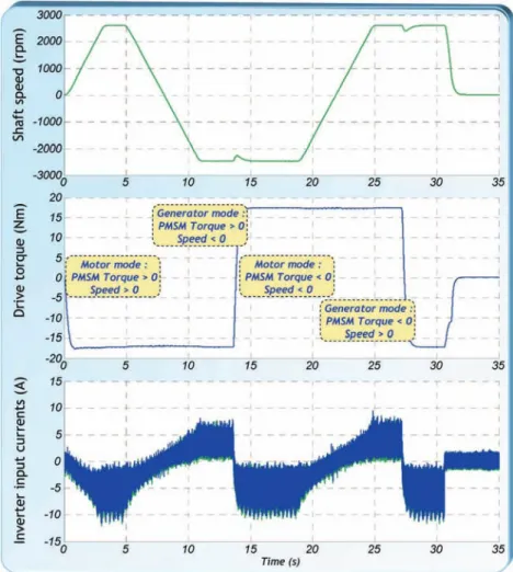
As the MAPFC integrates a reversible drive, the first objec-tive is to test the motor and generator modes. This is done in Fig. 6 where the transition between different operating points is described.
In this experimental test, the MAPFC torque is regulated, and the speed is controlled by the asynchronous machine. The system is able to operate at 2500 r/min in both generator and motor modes. The mechanical torque is 18 N · m in both modes too. The measured currents are the HVDC side input currents. Both inverters are supplying the same power to the machine which is the normal way to operate.
C. Power Balance Control
The theoretical study of the MAPFC has given two possi-bilities to balance powers from one HVDC side to the other. The first one uses the homopolar current independently from the actuation function, whereas the second possibility uses the actuation power repartition between the two inverters (i.e., Xact
quantity).
For readability reason, we will consider the power quantities at MAPFC electrical interfaces using the conventions and nota-tions in Fig. 7.
The use of Xact to share electrical power between the two
inverters is presented in Table I. This test consists in changing the power share of the left and right inverters from a 50/50 ratio to 5/95 and 95/5 ratios.
Due to the recovery time of diodes, it is impossible for inverters to operate a 0/100 or 100/0 ratio. As a result, the system has been designed to operate between ratios of 5/95 and 95/5. Beyond these values, the system enters a protection mode. The second degree of freedom helping in sharing power is the control of homopolar current through the stator windings of the machine. Different operating points have been synthesized in Table II.
The effect on current phase through the stator windings is shown by the addition of a mean value with the alternative component. Contrary to the test made with the Xact factor,
the power sharing is independent from the actuation function. Indeed, it is possible to transfer power without operating the PMSM only using machine inductances for power flow control. However, the machine must be designed to accept a continuous current through its stator windings.
These tests validate the operation of the MAPFC. It has been highlighted that two power sharing means may be used in the control of the system. The next section will discuss the use of these degrees of freedom in the frame of an embedded network in aeronautic context.
Fig. 6. Validation of actuation function of the MAPFC.
Fig. 7. Notations used for power sharing analysis.
IV. EMBEDDEDNETWORKOPERATIONS
The use of MAPFC is very attractive in an embedded net-work to replace a classical PMSM—inverter association like in an electric environmental cooling system application [25]. In-deed, these machines are important electric loads and have a fair inertia, which may be interesting during transient operations. Here, we choose to discuss the feasibility of two application cases of the MAPFC concept.
A. Voltage Regulation
The first application case is relative to the need of regulating an HVDC bus voltage during a transient reconfiguration (for
example, in case of generator failure) or during the starting sequence of the aircraft. The test configuration is described in Fig. 8.
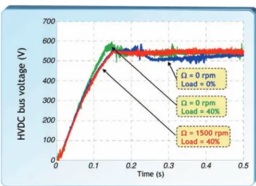
A DC bus voltage regulation loop cascaded with the ho-mopolar current control is added for that purpose. This loop is fully independent of the actuation function. The results of these experimental tests are reported in Fig. 9 that shows the HVDC bus voltage controlled by the MAPFC (nominal bus voltage is 540 V).
Three different operating cases are considered—for each of them, the MAPFC is able to regulate the DC voltage. A 100% load corresponds to the nominal power of the MAPFC. More-over, the tests confirm the system ability in terms of functional decoupling (actuation/power flow control), particularly as a high load is connected to the regulated bus bar.
B. Generator Power Balance
In this second test configuration, Xact is used to balance
the power supplied by the left and right generators. An addi-tional supervision device defines the Xact reference Xactref,
based on power measurements at HVDC sides. The relation is given in Xactref = 1 2 µ 1 − P L Load− PLoadR PL elec+ P R elec ¶ . (15)
TABLE I
POWERSHARINGUSINGXactQUANTITY
TABLE II
POWERSHARINGUSINGHOMOPOLARCURRENTREGULATION
Fig. 8. Voltage regulation using homopolar current.
Fig. 9. Experimental results of voltage regulation using homopolar current.
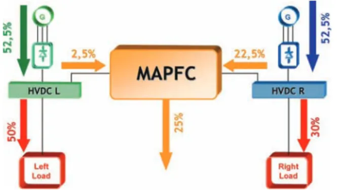
Fig. 10. Experimental results of generator power equalization using Xactat
initial state.
Fig. 10 shows the initial conditions of the test before acti-vating the power equalization, and Fig. 11 describes the final state.
Electrical powers are given in percentage of one generator total power, both generators being identical. As a result, each generator supplies 52.5% of its power capacity. This property of the MAPFC can help in reducing generator sizing in an intelligent integrated power management of the network.
V. CONCLUSION
In the framework of aircraft systems, this paper has presented an innovative solution valuable for large-power actuators em-bedded in electrical networks, but not exclusively. The theoret-ical study has described the system ability to use homopolar
Fig. 11. Experimental results of generator power equalization using Xactcat
final state.
current control in order to add a power transfer function useful in an HVDC network.
Moreover, the integration of this structure in an embedded environment offers new possibilities in terms of energy man-agement: On the one hand, it can be exploited in transient oper-ation while it can supply an HVDC bus bar without losing the actuation function. On the other hand, it can help to optimize the network sizing as such device is able to balance the generated powers regarding the power demand.
Even if the application is fully adapted to aeronautic net-works, any DC network may find advantages in using the struc-ture particularly taking into account that every AC machine type (synchronous but also induction machines) may be used.
REFERENCES
[1] W. Cao, B. Mecrow, G. Atkinson, J. Bennett, and D. Atkinson, “Overview of electric motor technologies used for More Electric Aircraft (MEA),”
IEEE Trans. Ind. Electron., to be published.
[2] K. Emadi and M. Ehsani, “Aircraft power systems: Technology, state of the art, and future trends,” IEEE Aerosp. Electron. Syst. Mag., vol. 15, no. 1, pp. 28–32, Jan. 2000.
[3] J. A. Rosero, J. A. Ortega, E. Aldabas, and L. Romeral, “Moving towards a more electric aircraft,” IEEE Aerosp. Electron. Syst. Mag., vol. 22, no. 3, pp. 3–9, Mar. 2007.
[4] N. Patin, L. Vido, E. Monmasson, J.-P. Louis, M. Gabsi, and M. Lecrivain, “Control of a hybrid excitation synchronous generator for aircraft ap-plications,” IEEE Trans. Ind. Electron., vol. 55, no. 10, pp. 3772–3783, Oct. 2008.
[5] F. J. Chivite-Zabalza, A. J. Forsyth, D. R. Trainer, J. Calvignac, S. Long, and R. Todd, “Control and development of an electrical systems eval-uation platform for uninhabited autonomous vehicles,” in Proc. IEEE
IECON, Nov. 2008, pp. 1479–1486.
[6] G. Gong, M. L. Heldweim, U. Drofenik, K. Mino, and J. W. Kolar, “Com-parative evaluation of three-phase high power factor AC–DC converter concepts for application in future more electric aircrafts,” in Proc. 19th
IEEE APEC, 2004, vol. 2, pp. 1152–1159.
[7] S. Girinon, C. Baumann, H. Piquet, and N. Roux, “Analytical modeling of the input admittance of an electric drive for stability analysis purposes,”
Eur. J. Phys., vol. 47, no. 1, p. 11101, 2009.
[8] D. Hernandez, M. Sautreuil, N. Retiere, D. Riu, and O. Sename, “A new methodology for aircraft power system design,” in Proc. ICIT, Gippland, Australia, Feb. 2009, pp. 1–6.
[9] L. R. Lewis, B. H. Cho, F. C. Lee, and B. A. Carpenter, “Modeling, analysis and design of distributed power systems,” in Proc. IEEE Power
Electron. Spec. Conf., 1989, pp. 152–159.
[10] M. Sautreuil, N. Retiere, D. Riu, and O. Sename, “A generic method for robust performance of aircraft DC power systems,” in Proc. 26th IEEE
IECON, Nov. 2008, pp. 49–54.
[11] K. W. E. Cheng, “Comparative study of AC/DC converters for more electric aircraft,” in Proc. 17th Int. Cof. Power Electron. Var. Speed Drives
(Conf. Publ. No. 456), Sep. 21–23, 1998, pp. 299–304.
[12] R. D. Middlebrook, “Input fliter considerations in design and applications of switching regulators,” in Conf. Rec. IEEE IAS Annu. Meeting, 1976, pp. 366–382.
[13] P. Liutanakul, S. Pierfederici, and F. Meibody-Tabar, “Load power com-pensations for stabilized DC—Link voltage of the cascade controlled rectifier/inverter—Motor drive system,” in Proc. IEEE IECON, 2005, pp. 231–238.
[14] K. Louati, D. Sadarnac, and C. Karimi, “Input filter influence on the stability of DC/DC converters,” in Proc. IEEE ISIE, 2004, vol. 2, pp. 1165–1171.
[15] A. Emadi, A. Khaligh, C. H. Rivetta, and G. A. Williamson, “Constant power loads and negative impedance instability in automotive systems: Definition, modeling, stability and control of power electronic converters and motor drives,” IEEE Trans. Veh. Technol., vol. 55, no. 4, pp. 1112– 1125, Jul. 2006.
[16] N. Hur, J. Jung, and K. Nam, “A fast dynamic DC—Link power balancing scheme for a PWM converter—Inverter system,” IEEE Trans. Ind.
Elec-tron., vol. 48, no. 4, pp. 794–803, Aug. 2001.
[17] M. P. Kazmierkowski and L. Malesani, “Current control techniques for three-phase voltage source PWM Converters: A survey,” IEEE Trans. Ind.
Electron., vol. 45, no. 5, pp. 691–703, Oct. 1998.
[18] D. Boroyevich and M. Jadric, “Modeling and control of a synchronous generator with an active DC load,” IEEE Trans. Power Electron., vol. 15, no. 2, pp. 303–311, Mar. 2000.
[19] B. V. Reddy, V. T. Somasekhar, and Y. Kalyan, “Decoupled space-vector PWM strategies for a four-level asymmetrical open-end winding induction motor drive with waveform symmetries,” IEEE Trans. Ind. Electron., vol. 58, no. 11, pp. 5130–5141, Nov. 2011.
[20] K. Junha, J. Jinhwan, and N. Kwanghee, “Dual-inverter control strategy for high-speed operation of EV induction motors,” IEEE Trans. Ind.
Electron., vol. 51, no. 2, pp. 312–320, Apr. 2004.
[21] B. A. Welchko and J. M. Nagashima, “A comparative evaluation of motor drive topologies for low-voltage, high-power EV/HEV propulsion sys-tems,” in Proc. IEEE ISIE, 2003, vol. 1, pp. 379–384.
[22] B. A. Welchko, “A double-ended inverter system for the combined propul-sion and energy management functions in hybrid vehicles with energy storage,” in Proc. IEEE IECON, 2005, pp. 1–6.
[23] E. Levi, “Multiphase electric machines for variable-speed applications,”
IEEE Trans. Ind. Electron., vol. 55, no. 5, pp. 1893–1909, May 2008. [24] J.-W. Choi and S.-C. Lee, “Antiwindup strategy for PI-type speed
con-troller,” IEEE Trans. Ind. Electron., vol. 56, no. 6, pp. 2039–2046, Jun. 2009.
[25] R. De Maglie, G. Osvald, J. Engstler, A. Engler, and J.-P. Carayon, “Op-timized 70 kW power inverter dedicated to future aircraft application,” in
Proc. EPE Conf., Barcelona, Spain, Sep. 2009, pp. 1–10.
[26] N. Patin, L. Vido, E. Monmasson, J. P. Louis, M. Gabsi, and M. Lecrivain, “Control of a hybrid excitation synchronous generator for aircraft ap-plications,” IEEE Trans. Ind. Electron., vol. 55, no. 10, pp. 3772–3783, Oct. 2008.
[27] J. W. Choi and S. C. Lee, “Antiwindup strategy for PI-type speed con-troller,” IEEE Trans. Ind. Electron., vol. 56, no. 6, pp. 2039–2046, Jun. 2009.
Cédric Baumann received the Ph.D. degree in electrical engineering from the Institut National Polytechnique de Toulouse (INPT), Toulouse, France, in 2009.
Since 2009, he has been with Airbus Operations S.A.S, Toulouse, where he was an Electrical Net-work Engineer with the Electrical Research Depart-ment and has been responsible for the verification and validation of the electrical distribution system for the A350 XWB within Airbus design office since 2011. His activities were focused on embedded power electronics on aircraft distribution systems and improving electrical load analysis methods.
Hubert Piquet received the B.S. degree in ap-plied physics from the Ecole Normale Supérieure de Cachan, Cachan, France, in 1984, and the Ph.D. degree in electrical engineering from the Institut Na-tional Polytechnique de Toulouse, Toulouse, France, in 1990.
He is currently a Professor at the École Nationale Supérieure d’Électronique, d’Électrotechnique, d’Informatique, d’Hydraulique et des Télécommu-nications, Institut National Polytechnique de Toulouse–Université Paul Sabatier–Centre National de la Recherche Scientifique, Université de Toulouse, Toulouse, France, where he teaches power electronics. His research activity takes place in the Laboratoire Plasma et Conversion d’Energie, Toulouse. Quality and stability in embedded networks as well as power supplies for plasma applications are his main domains of research.
Xavier Roboam (M’96) received the Ph.D. de-gree in electrical engineering from the Institut Na-tional Polytechnique de Toulouse (INPT), Toulouse, France, in 1991.
Since 1992, he has been with the Laboratory of Electrotechnics and Industrial Electronics (Unite Mixte de Recherche), Ecole Nationale Supérieure d’Electrotechnique, d’Electronique, d’Informatique, d’Hydraulique et des Télécommunications, INPT/Centre National de la Recherche Scientifique (CNRS), Toulouse, as a CNRS full-time Researcher. Since 1998, he has been the Head of the team “G-Enesys,” the objective of which is to process design problems at the “system level.” He develops design methodologies specifically oriented toward multifield systems design for applications such as electrical embedded systems and renewable energy systems.
Eric Bruwas born in Lavelanet, France, in 1968. He received the M.Sc. degree in electric engineering from the Conservatoire National des Arts et Métiers, Toulouse, France, in 2005.
Since 2006, he has been with the Laboratoire Plasma et Conversion d’Energie, École Nationale Supérieure d’Électronique, d’Électrotechnique, d’Informatique, d’Hydraulique et des Télécom-munications, Institut National Polytechnique de Toulouse–Université Paul Sabatier–Centre National de la Recherche Scientifique, Université de Toulouse, Toulouse, as a Test Engineer. With the G-Enesys team, he develops test benches devoted to HVDC networks, renewable energy systems, and hybridization devices with electrical storage such as ultracapacitor or electrochemical accumulators.