Any correspondence concerning this service should be sent to the repository administrator: [email protected]
Official URL:
http://www.scientific.net/AMR.423.128
This is an author-deposited version published in: http://oatao.univ-toulouse.fr/ Eprints ID: 8484To cite this version:
Popa, Andreï and Baili, Maher and Dessein, Gilles and Dutilh, Vincent
Identification of tool failure modes in drilling Udimet® 720 superalloy. (2011)
In: International conference on structural analysis of advanced materials, 7 - 10
Sept 2011, Sinaia, Romania.
O
pen
A
rchive
T
oulouse
A
rchive
O
uverte (
OATAO
)
OATAO is an open access repository that collects the work of Toulouse researchers and makes it freely available over the web where possible.
Identification of tool failure modes in drilling Udimet
®720 superalloy
Andrei Popa a, Maher Baili a, Gilles Dessein a, Vincent Dutilh b a
Université de Toulouse, INPT- ENIT, Laboratoire Génie de Production – 47 avenue d'Azereix – 65016 TARBES
b
Turboméca Bordes, 64511 Bordes Cedex
Abstract
The ACCENT Project (FP7- AAT- 2007- RTD-1) will allow the European Aero Engine manufacturers to improve their competitiveness by applying adaptive control techniques to the manufacturing of their components. For the critical rotating parts of aircraft engines, the surface integrity generated after machining is a key factor on the life cycle. In this context, one particular attention has to be carried on tool condition. The aim of this paper is to identify the main failure modes characterizing this particular Nickel base drilling. By experimental techniques, cartography of failure modes was realized. The results show that flank wear and notching are the main failure modes limiting the tool life. For some cutting conditions, the tool failure arrives after the first hole due to the important cutting forces. Some interesting associations are made between the spindle current/accelerometers/ thrust force and flank wear, tool breakage and notching.
1 Introduction
The super alloys can be classified in three categories: Nickel base, Iron base and Cobalt base. In the aircraft industry, the Nickel base super alloys are often employed in the applications at high temperature, such as turbine discs. The Udimet® 720 has replaced the Inconel 718 due to its higher mechanical properties at elevated temperatures and other advantages in terms of corrosion resistance. However, their properties, the tool life and anomalies which may occur during the machining, make the Nickel base super alloys “difficult-to-cut” [1]. The choice of cutting parameters (cutting speed, feedrate, percentage of emulsion in cutting fluid, etc), the low thermal conductivity which characterize these materials, the chemical affinity for tool materials, the tool geometry and the coating type are essential factors on the tool life.
A tool geometry variation (i.e. built-up edge, chipping, excessive wear or tool failure) during drilling can lead to surface integrity problems (roughness profile deviation, thermo-mechanically affected layer, etc.). For the critical parts, it is crucial to prevent these anomalies. All these appreciations make the tool wear a key factor for the quality of produced parts.
Sharman et al. [2] show the influence of the geometry and type of coating on the tool life in drilling of Inconel 718. In this study, the drills having a curved edge and radius on the periphery had a higher performance comparing to drills with either a straight or concave cutting edge or sharp periphery. In the same direction, for turning of Inconel 718 without lubricant, Devillez et al. [3] present the influence of coating type. Several coatings were evaluated on different cutting speed, chosen between 20 and 200 m/min and feederate 0.1 and 0.2mm/rev. The best coated type was used for a bar turning operation. During these tests, the principal wear modes were welding, adhesion of workpiece material onto the tool and abrasion flank wear. Chen [4] studied the wear mechanisms in drilling Inconel 718 with multi-layer TiAlN PVD coated tungsten carbide twist drills. Selected cutting speed was 13.2 m/min and feedrate was 0.1 mm/rev. The authors explained the wear evolution by dividing into four steps. At first phase, due to the friction force, the
coated layer is removed. The next period is represented by the apparition of flank wear and chipping. For the third stage, micro cracks appear in the chipping region. Finally, corroborating with crater wear causes the drill failure.
More and more researches are focused on process monitoring, and more precisely by using physical measures as non-destructive control. Generally, two types of methods (direct and indirect) can be applied. Most of direct methods (e.g. cameras for visual inspection or laser beams) can be employed only as laboratories technics (even they have a high accuracy), due to some limitations in industry, such as use of cutting fluid, low light, etc. Indirect methods are based on physical quantities, such as cutting forces, power, temperature being more suitable for industrial applications. A large number of papers deal with Tool Condition Monitoring (TCM). Jantunen [5] presents principals monitoring technics and signal analyses available in the literature. Statistical parameters (mean value, maximum value, kurtosis, skewness, etc.), frequency analyses on signals are used in order to monitor the tool condition.
The power signal recorded during the machining is compared by Axinte [6] with force and torque signals in order to verify the sensitivity of this physical quantity in tool condition monitoring. In continuous machining processes, i.e. turning and drilling, the power can be considered appropriate to detect both chipping and gradual tool wear. On other hand, for the intermittent processes (milling) the power is not sensitive enough to identify a chipped cutter. This can be attributed to the fact that this signal lost the intermittent “sow teeth” patterns, that’s allowed to detect eventual events.
The vibration signal is often used as source of information about the process. In drilling of high speed steel C 1040, Abu-Mahfouz [7] uses features extracted by vibration signal as input parameters in neural network for prediction and classification of wear (chisel wear, crater wear, flank wear, edge fracture). Another interesting approach is proposed by Kalvoda [8]. The author uses a new method of time-frequency analysis, Hilbert Huang Transform (HHT), to extract features of sensor signals. It consists of two steps: the Empirical Mode Decomposition (EMD) to decompose a signal into a set of monocomponent signals, called Intrinsic Mode Functions (IMFs), and the application of the HHT to the IMFs. Then Hilbert Spectral Analysis (HSA) it is used to examine the IMFs instantaneous frequency and to generate effective time–frequency distributions called Hilbert spectra.
2 Experiments
Drilling tests were carried on ∅80 mm forged bars, usually used as raw material in turbine discs manufacturing. These bars have the same heat treatments as the discs (solution Heat Treatment and aged) in order to obtain the nearest routine mechanical properties to the original discs (same microstructure, same grain size 8 (ASTM) and same Hardness HV 410 HV30).
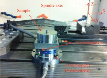
Figure 1. Experimental set-up and PM signals
Accelerometers 4 Components Dynamometer Sample Spindle axis Z X Y
The tool is a ∅15.5 mm drill Iscar Chamdrill with an interchangeable TiAlN coated carbide head. This drill has the particularity of having a very short margin (4 mm), which avoids anomalies generated by frictions forces all along the hole.
The operation is a drilling in a pre-hole ∅13 mm. The length of the hole is 37 mm.
All tests were made in a HURON KX10 3-axis vertical milling center using an 18kW spindle motor and a Siemens 840D numerical controller. The cutting fluid pressure was fixed at 17 bars.
The machine-tool was instrumented by a 4 component Kistler dynamometer (Fx, Fy, Fz and Mz) and three accelerometers following X, Y and Z directions. Spindle power, position in Z axis, spindle current intensity and current intensity in the three axes are recorded through Siemens Profibus.
All the work done in this paper is a part of European Project ACCENT (Adaptive Control of Manufacturing Processes for a New Generation of Jet Engine Components). The main objective of this project is to reduce the uncertainty in fabrication by using Process Monitoring. Several experimental campaigns were implemented:
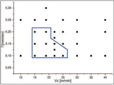
1. Combining the cutting conditions according to classic criteria established by the French specification AFNOR E66-520 (Couple-Tool-Material) to find the optimal cutting speed and feedrate.
2. New operating points (Figure 2) were tested and analyzed using surface integrity criteria in order to define an Acceptable Surface Integrity Domain (A.S.I.D – a window that insures the piece integrity). 3. Machining disturbances (corresponding to tool position defect, cutting fluid emulsion variation or
changes of the material hardness) were tested to understand their impact on surface integrity and signals.
4. The purpose of the last campaign was to understand the wear behavior for this combination process-material. Based on “Cartography” tests results (Figure 2), several cutting conditions were chosen to drill more than just one hole with the same tool. This stage will help to identify the wear mechanisms. All the tested points will be described in chapter 3.
Figure 2. Cartography tests and ASID
3 Results
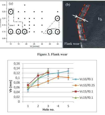
Results of drilling tests performed in Udimet 720® are presented in terms of failure modes and evolution of physical measurements. After each test, images of the tool were taken with a binocular. To avoid possible damages due to the handling, the tool was left attached on the tool holder. For the flank wear, the mean value was measured. For the notch, only the surface was considered in this study.
3.1 Evolution of failure modes 3.1.1 Tool flank wear
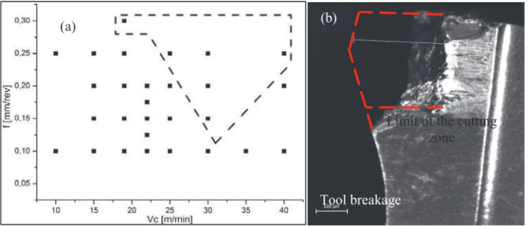
The first wear type identified was the flank wear. The coated layer is abraded-off, due to the friction force. In the Figure 3(a) two zones are delimited. The first one corresponds to cutting speeds lower than 20 m/min and feedrates 0.1 mm/rev and 0.25 mm/rev. The black circles represent the cutting conditions chosen to drill several holes with the same tool (in production the tool life is limited at 2 holes). Finally were performed 5 holes for Vc 10 m/min and 3 holes for the other two points. The results of these tests (Figure 4) show a slow increase in terms of flank wear, between 0.05 mm and 0.13 mm (the uncertainty is 0.01 mm).
Contrary to this zone, at high cutting speeds the tool behavior is totally different. In the second zone, 2 holes were performed for each point. Initially, the first machining is stable and the results in terms of flank wear are quite similar with tests at low cutting speed. The difference is made by the second hole, having as direct consequence the tool breakage. The recorded signals indicate that the tool failure arrives immediately after the tool entrance in the material (Figure 8b - grey curve).
Figure 3. Flank wear
Figure 4. Flank wear evolution
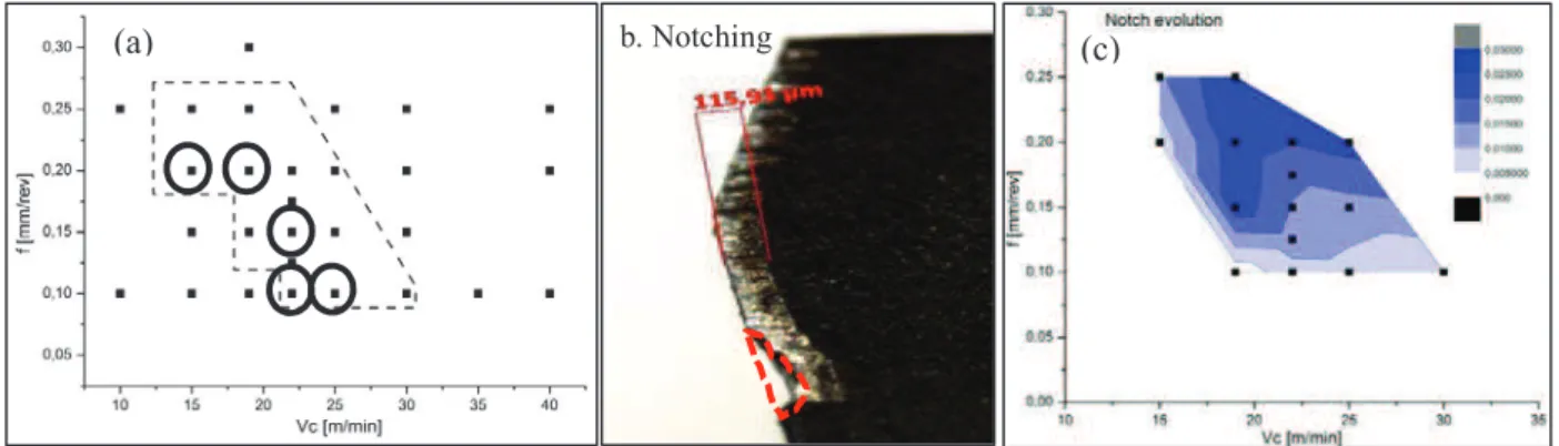
3.1.2 Notching
Due to the specifity of the process (drilling in a pre-hole) another failure mode observed is the notch wear. The notch apparition is explained by the difference of pressure at the limit of cutting zone. Figure 5b presents the second zone proposed in this study, characterized by flank wear and notching.
Flank wear
Figure 5. a). Notching domain; b). Example of measures ; c). Evolution after the first machining
The flank wear evolution follows the same pattern as before. A slow increasing could be observed for tests having a low feedrate. For cutting speed Vc 19 m/min and feedrate 0.2 mm/rev the increasing is more emphasized (more than 50% between 2 holes). At 25 m/min, the results are more interesting. After the first hole, the wear level is about 0.05 mm and is increasing until 0.18 mm for the second test. Further, the tool breakage occurs. For one cutting condition, Vc 22 m/min and f 0.15 mm/rev were performed 10 tests with the same tool. It seems that the tool honing is done after the first hole and further the wear is slowly increasing (between 0.1 and 0.15 mm).
Figure 6. Flank wear and notching evolution
The notching evolution after the first hole is presented in the Figure 5c. It is obvious that with higher feedrates, the notch dimensions are increasing.
3.1.3 Tool breakage
When cutting forces become too high, the tool breakage occurs at the limit of the cutting zone (Figure 7b).
b. Notching
Figure 7. a.Tool breakage domain ; b. Example
Figure 7b illustrates an image with tool breakage. It’s the consequence of the most severe cutting conditions, Vc 40 m/min and f 0.25 mm/rev. The same results were obtained for the others points tested.
4 Evolution of signals
The first part of this work highlights the tool behavior over a wide range of cutting conditions. In this section, the signals will be analyzed in order to verify which one is more suitable for tool condition monitoring. The signals considered are:
- The signals obtained from the Kistler dynamometer (Mz, Fz, Fx and Fy) are filtered with a low pass (25 Hz).
- The accelerometers are another interesting source of information. It must to be mentioned the fact that all the three accelerometers offers the same signal. The only difference is the signal amplitude, caused by distinct length to the cutting zone. A hammer test was performed in order to identify the natural frequencies corresponding to spindle, tool holder, etc.
- The last signal considered is the spindle current extracted from NC machine-tool.
Figure 8(a) shows the evolution of the current spindle for the 5 holes drilled at Vc 10 m/min and f 0.25 mm/rev. The gradual flank wear observed during these tests could be related with the increased amplitude of spindle current. The same results were obtained using thrust force. In terms of vibrations, the tool wear generates an expansion of contact area, having as consequence lower amplitudes (Figure 8b).
An example is given for the notching wear in the Figure 8(c). The torque Mz, filtered with a low pass and the spindle current have the same topography. This pattern is representative for all the tests presenting a notch. Usually, is characterized by a stable machining (this length is function of cutting conditions) followed by suddenly increased amplitude of signals. The contact area between the tool and the piece increases when a notch occurs, making the cutting forces to evolve as presented. The vibration signal obtained from the accelerometer placed along Y axis show a similar pattern with the spindle current. Has to be mentioned that signal is unfiltered.
In the Figure 8(e) and (f) two examples of tool breakage detection are presented. The cutting forces are increasing (two or three times) followed by a stable machining. But, in this situation, the cutting action is replaced by extrusion. The chips thickness is about two times lower.
Tool breakage
Limit of the cutting zone
Figure 8. Failure modes detection using physical measurements
It is interesting to remark that the cutting forces are increasing with higher feedrates. Also, at 40 m/min the average spindle current is similar with tests at 10 m/min. This observation could be explained by the thermal softening. The temperature during machining is increasing due to the severe cutting conditions, making the cutting forces to decrease (Figure 9).
(a) (b)
(c) (d)
Figure 9. Spindle current evolution
6 Conclusions
This paper presents the results in term of failure modes for the drilling of Udimet 720®, obtained from an experimental campaign. All the trials were monitored with a four components dynamometer, three accelerometers and the signals extract from the machine-tool NC.
The results show that flank wear and notching are the main failure modes. The flank wear is slowly increasing. The notch surface increase with higher feedrate and when the cutting forces become too important the tool breakage occurs.
Cartography of failure modes was realized from these results. But, it might change due to the variability on the quality of manufactured tools (Figure 10).
In terms of tool condition monitoring, promising results could be obtained by associating the flank wear/notch with the spindle current, accelerometers or thrust force. Nevertheless, the spindle current signal issue from machine NC has the advantage to be already filtered and easy to implement in a process monitoring technique for industrial partners, together with the accelerometers.
Even some observations are made for the accelerations signals, the next steps of this work should be focus on this direction.
Acknowledgments
The research leading to these results has received funding from the European Community's Seventh framework Programme (FP7/2007-2011) under grant agreement number 213855.
References
[1] E.O. EZUGWU, 2005, Key improvements in the machining of difficult-to-cut aerospace superalloys, International Journal of Machine Tools and Manufacture, 45, 1353–1367
[2] A.R.C. Sharman, A. Amarasinghe, K. Ridgway, 2008, Tool life and surface integrity aspects when drilling and hole making in Inconel 718, Journal of materials processing technology, 200, 424 – 432.
[3] A. Devillez, F. Schneider, S. Dominiak, D. Dudzinski, D. Larrouquere, 2007, Cutting forces and wear in dry machining of Inconel 718 with coated carbide tools,Wear, 262, 931 – 942.
[4] Y.C. Chen, Y.S. Liao, 2003, Study on wear mechanisms in drilling of Inconel 718 superalloy, Journal of Materials Processing Technology, 140, 269 – 273.
[5] E. Jantunen, 2002, A summary of methods applied to tool condition monitoring in drilling, International Journal of Machine Tools and Manufacture, 42, 997- 1010.
[6] D. Axinte, N. Gindy, Assessment of the effectiveness of a spindle power signal for tool condition monitoring in machining processes, 2004, International Journal of Production Research, 42, 2679 – 2691. [7] I. Abu-Mahfouz, 2003, Drilling wear detection and classification using vibration signals and artificial neural network, International Journal of Machine Tools and Manufacture, 43, 707 – 720.
[8] T. Kalvoda, Y.R Hwang, A cutter tool monitoring in machining process using Hilbert-Huang transform, International Journal of Machine Tools and Manufacture, 2010, 50, 495 – 501.