Building Tomorrow’s Society Bâtir la Société de Demain
Fredericton, Canada
June 13 – June 16, 2018/ Juin 13 – Juin 16, 2018
FAILURE ANALYSIS OF TRANSMISSION LINE STEEL LATTICE TOWERS
SUBJECTED TO EXTREME LOADING
Sad Saoud, K.
1, Langlois, S.
1,2, Loignon, A.
1and Lamarche, C.-P.
1 1 Université de Sherbrooke, Canada2[email protected] (corresponding author email)
Abstract: Lattice towers are extensively used in overhead transmission lines, owing primarily to their lightness and cost-effectiveness. The modeling of such structures is usually laborious due to various complex factors including connection eccentricities, rotational stiffness of connections, bolt slippage, among others. Therefore, full-scale tests are usually performed for the qualification of new overhead line supports, which is a time-consuming and expensive process. Numerical models used in practice rely on simplified hypotheses, using linear truss/beam elements assumed to be pin-connected at both ends. Such models are combined with standard design equations to only evaluate the members’ axial capacities. Finite element models involving solid/shell elements are generally more accurate, though, the computational cost of the resulting problems makes it very difficult to evaluate the response of a complete tower. This paper presents an advanced numerical approach using beam elements aimed at predicting the load-bearing resistance of steel lattice towers under static load cases. Such approach will serve not only to verify the design of new towers, but also to understand various phenomena leading to the collapse of towers in the case of premature failures. The proposed model is developed using the finite element package Code_Aster, wherein lattice towers are modeled using spatial beams. The highly nonlinear problem is solved in an incremental way using advanced features to deal with both geometric and material nonlinearities. An example of a lattice tower loaded until failure is presented and compared with analogous experimental test. The effect of different geometric imperfections on the failure is particularly highlighted.
1 INTRODUCTION
The continuous expansion in the worldwide demand for electrical energy brings major challenges to power transmission system operators, who actively work towards the continuous improvement of their services. To accommodate the increasing power consumption, new transmission line towers need to be designed and existing structures must be upgraded to withstand heavier loads. Among other concerns, ensuring the structural integrity of transmission infrastructures, under normal as well as extreme weather events, is of substantial value to guarantee the electrical networks’ safety and reliability, and thereby significantly limit the occurrence of power outages.
Steel lattice towers are intensively employed in high-voltage transmission lines because of their lightweight construction and excellent strength achieved at a relatively low cost. These towers are conventionally composed of straight angle members connected together by means of various bolted joints, which results in cumbersome structural systems often exhibiting complex structural behaviors. Accordingly, destructive testing on full-size towers are currently required to assess their vulnerability under the most critical loading conditions before being brought into service. This process is usually costly and time-consuming, and there
is therefore a need to develop accurate numerical approaches with a view to redressing the lack of awareness and understanding of lattice structures.
The most popular modeling approach used in the design of transmission towers assumes lattice structures to be linear space trusses, where secondary bracing elements are generally not included in the model [Kitipornchai et al. (2005)]. In such representations, towers are designed to only carry axial forces, as the angle members are assembled using exclusively pin-ended connections [CIGRE (2014)]. Various nonlinear effects are generally accounted for by modifying the effective length of members in the design equations [Rao and Kalyanaraman (2001)]. In a 3D model exclusively composed of truss elements, numerical instabilities occur, and hence supplementary efforts are required to remove them [Al-Bermani and Kitipornchai (1992)]. Moreover, Eltaly et al. (2014) reported that almost a quarter of the tested towers, designed using the above-mentioned method, experienced premature failures, often at unexpected locations.
Modeling approaches using beam elements may represent a good compromise between accuracy and computational costs, as shown in the study by Rao and Kalyanaraman (2001). This requires the consideration of various complex phenomena concerning the connections, such as stiffness and slippage. Also, initial geometric imperfections, including either connection eccentricities or out-of-straightness of the members, may have a significant impact on the stability response of lattice towers. However, the relative contribution of each type of imperfection on the global response of lattice towers is poorly understood and thus should be closely investigated.
In this paper, a finite element modeling approach for the numerical analysis of the structural behavior of steel lattice towers under static load cases is presented. The proposed modeling approach is developed using the finite element software Code_Aster. This modeling approach uses three-dimensional beam elements accounting for warping to model the inelastic behavior of steel angle members, and linear discrete elements to represent the bolted connections. Other factors such as connection eccentricity and joint stiffness are also incorporated in this model. The resulting highly nonlinear problem is solved incrementally using advanced features implemented in Code_Aster to cope with both geometric and material nonlinearities up to advanced post-critical stages. This work focusses on the study of the impact of two different geometric imperfections, namely the out-of-straightness and the connection eccentricities, on the post-buckling response of steel lattice towers under static load cases. An example of a tower quasi-statically loaded until failure is analyzed herein. The numerical results are compared with similar laboratory tests performed on a complete 8 m tall downscaled lattice tower specimen. This analysis results emphasize the high sensitivity of steel lattice towers to geometric imperfections.
2 FRAMEWORK AND MODELING PROCEDURE
The analysis of steel lattice towers is carried out using the open-source software Code_Aster [Code_Aster (2017)]. The assumptions used in the modeling of each single element composing the lattice towers are summarized below.
2.1 Angle members
The modeling of the behavior of angle members is performed using spatial beam elements based on Timoshenko beam theory accounting for transverse shear and warping effects. The resulting beam element with seven degrees-of-freedom can undergo finite displacements and rotations, while strains are assumed to be small. In practice, a large amount of lattice towers fails due to yielding of the thin-walled angle sections. Hence, the formulation of the beam element also integrates an elastoplastic material model, based on the von Mises yield criterion. The governing equations for the beam element are derived within an Updated-Lagrangian framework.
2.2 Connections
There is a large amount of bolted connections in steel lattice towers. The increase (or reduction) of the local stiffness at the various connection locations as well as the introduction of load eccentricities that is inherent to these connections has a major effect on the global behavior of the structures. In this modeling, their behavior is represented using discrete elements attached to two superimposed nodes. Each discrete element has a total number of 12 uncoupled degrees of freedom (3 translations and 3 rotations per node) obeying a linear elastic constitutive law. The stiffness of the connections may thus be controlled by modifying the stiffness coefficients of the discrete elements (springs). In this study, multi-bolt connections are considered as semi-rigid, whereas one-bolt connections are assumed to be pinned about the bolt axis and rigid in the other directions. The behavior of the connection is therefore controlled by the value assigned to the rotational stiffness coefficient about the bolt axis. These values are selected based on a study of typical connections in various lattice towers [Bouchard (2013)]. In this paper, unless otherwise specified, the expressions ‘semi-rigid model’ and ‘flexible model’ will be used to designate one-bolt connections with high, and low stiffness coefficients, respectively. The actual behavior of lattice towers is believed to be bounded between these two extreme cases.
It is worth-mentioning that nonlinear effects including bolt slippage and connection yielding are not accounted for in the present study for practical reasons. This assumption may significantly affect tower flexibility, but it is not believed to greatly influence the towers’ ultimate capacity, as shown in a study by Al-Bermani and Kitipornchai (1992).
2.3 Eccentricities
Steel angle members are generally connected eccentrically. In the case of angle members connected by only one leg, a rigid link is used to connect the centroid of the angle section to the connection point assumed to be located in the middle of the connected leg. A similar procedure is also adopted in the specific case of angle members connected on both legs. However, the connection point in this case coincides with the angle member’s heel.
Once derived, the nonlinear problem is solved incrementally using Newton’s method. At the beginning of the incremental static analysis, also referred to as pushover analysis, use is made of classical force control method. In the vicinity of limit points, the control strategy is manually switched to the path-following arc-length method [Crisfield (1981)] to effectively circumvent possible nonlinear behaviors such as snap-through or snap-back buckling, and thus analyze advanced post-buckling responses.
3 APPLICATION EXAMPLE 3.1 Problem statement
The accuracy of the numerical procedure described above has been assessed in ongoing works by the authors by comparing numerical simulations’ results obtained from various lattice towers with experimental test results of lattice towers subjected to extreme loading conditions. In the present work, the developed modeling procedure will be used to analyze the way in which the choice of the initial geometric imperfection may affect the buckling response of steel lattice towers. The impact of the stiffness of bolted connections on the structural response will also be briefly investigated.
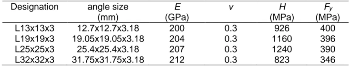
The analyzed lattice tower is presented in Figure 1. This structure measuring 8 m in height was tested experimentally [Loignon (2015)], and the results of the test are used in this study for validation purposes. It represents a small-scale version of a transmission line tower, composed of simple equal-leg angles. The geometric characteristics of the equal-leg angles are reported in Table 1. For each angle member listed in Table 1, five coupon tests were conducted, using a universal testing machine with a load capacity of 100 kN in accordance with the specifications of ASTM A370 – 12a standard testing methods [ASTM (2012)], to establish average values for the material properties. For the sake of simplicity, a bilinear elastoplastic material model is considered. The slope of the plastic curve, denoted H, is determined based on the concept
of equal energy dissipation, so that the areas under the curves comprised between the yield point and ultimate tensile strain are the same [Foster (2015)]. Accordingly, the Young’s modulus E, Poisson’s ratio ν (assumed value), yield strength Fy, and tangent modulus H are given in Table 1.
Figure 1: Self-supporting lattice tower
Table 1: Geometric and material properties of the angle members constituting the analyzed tower. Designation angle size
(mm) E (GPa) ν H (MPa) Fy (MPa) L13x13x3 12.7x12.7x3.18 200 0.3 926 400 L19x19x3 L25x25x3 L32x32x3 19.05x19.05x3.18 25.4x25.4x3.18 31.75x31.75x3.18 204 207 212 0.3 0.3 0.3 1160 1240 823 396 390 346
The loading pattern composed of gravity load of constant value as well as vertical load and transverse load, denoted V and T, respectively (in the -z and -x direction, respectively), is applied at the tip of each cross-arm composing the tower (see Figure 1 for the location of the loading points). Table 2 summarizes the intensity of the applied loading, which corresponds to the ultimate loads recorded experimentally.
Table 2: Ultimate load combination for the analyzed lattice tower. Loading point V (kN) T (kN) 1 2 1.36 1.36 3.01 2.90 3 1.36 3.08
The tower is fixed at its base. The degrees-of-freedom related to warping are restrained at every joint composing the tower, thus inducing non-uniform stresses along the beams.
The mesh of each angle member composing the tower is achieved using a total number of 15 linear elements (first-order interpolation), in accordance with a preliminary mesh convergence analysis.
For the study of the effect of geometric imperfections, let us recall that two types are considered, namely eccentricities and initial out-of-straightness defects. In the case of eccentricities, the modeling methodology described previously is used, and the effect of the stiffness of the connections is briefly analyzed. However, in the case of initial out-of-straightness defects, the methodology is slightly modified so as to neglect the member eccentricities (connected member centroids meet at a unique point).
3.2 Results and analysis
The result of the experimental test performed on the lattice tower is presented in Figure 2. First, the buckling of two diagonal members in the lower part of the tower was observed shortly after the beginning of the loading process, but without affecting the global stability of the whole structure (see Figure 2(b)).
Figure 2: Experimental set-up and failure mode [Loignon (2015)].
The test was then pursued until the onset of a secondary buckling in the upper part of the tower body, as shown in Figure 2(c), leading to the global instability of the structure [Loignon (2015)].
a) tested tower
b) primary buckling
As mentioned above, the laboratory test is reproduced numerically considering two different geometric imperfections. The use of geometric imperfections is necessary to initiate the buckling of the structure. In the case of eccentricities, the modeling approach described previously is used without any additional treatment. However, a linearized buckling analysis is performed prior to the pushover test in the case of out-of-straightness defects. Figure 3 presents the first three buckling modes (with eigenvalues λ sorted in ascending order) obtained for the analyzed structure. Notice that the buckling modes and associated eigenvalues depicted in Figure 3 corresponds to the case in which all connections are modeled as concentric. These modes are similar to those obtained for the tower considering eccentricities.
Figure 3: First three buckling modes of the analyzed tower.
Mode 3 (λ = 1.32) Mode 2 (λ = 0.95)
The post-buckling deformed shapes obtained numerically are depicted in Figure 4. On the left-hand side, Figure 4(a) shows the failure mechanism of the tower considering connection eccentricities, which turns out to be similar to the one observed experimentally (see Figure 2). It is observed that both the semi-rigid model and flexible model lead to similar post-buckling configurations, that is to say the rotational stiffness of the one-bolt connections here do not alter the buckling mechanism. The right-hand side of Figure 4(b) corresponds to the case of the analysis considering the initial out-of-straightness. In this case, the first critical mode determined from the linearized buckling analysis (having the lowest buckling load factor λ), which is identical to the first buckling occurrence observed experimentally, is employed to pre-deform the analyzed tower. The amplitude of the initial imperfection, denoted r, was varied to take the following values: 1/1000, 1/100, and 1/10. In all cases, the pushover test exhibits an instability localized in the lower part of the structure. No secondary buckling was observed, even when considering small amplitude of the initial imperfection. Therefore, in order to analyze the effect of pre-deforming the upper part of the tower, mode 3 with r =1/1000, which is a realistic defect size, was used as an out-of-straightness defect. As in the previous case, the result simply shows the amplification of mode 3, and no buckling mode was observed in the lower part of the structure. A supplementary analysis combining both connection eccentricities and out-of-straightness defect (considering mode 3) shows that the response is similar to the response observed during the experimental test. The out-of-straightness defect simply decreases the load-bearing capacity of the structure without affecting its mechanical behavior.
Figure 4: Deformed structure obtained numerically.
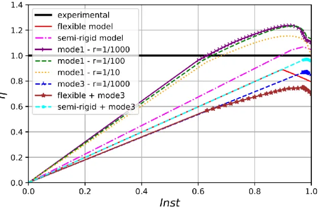
The load factor
ᶯ,
defined as the ratio between the load increment and the applied loading (for instance, a load factor of 1 corresponds to the experimental ultimate load level), is plotted in Figure 5 for each of the cases studied previously. The sequence Inst does not have any physical meaning in this static analysis. It only specifies how the applied load is incremented. Figure 5 shows that the ultimate resistance of the lattice tower is influenced by both the imperfection type and the rotational stiffness of one-bolt connections. Nevertheless, considering only eccentricities yields to a collapse behavior closer to the one observed duringthe experimental test. The comparison also indicates that the carrying capacity of the tower analyzed using mode 1 as an initial out-of-straightness defect is much higher than the one corresponding to mode 3. Finally, the combination of connection eccentricities and a realistic out-of-straightness defect slightly reduces the tower ultimate capacity.
Figure 5: Comparison of various responses of the analyzed lattice tower.
The maximum values of the load factor corresponding to the simulations presented Figure 5 are reported in Table 3, where the experimental ultimate capacity of the tower is bounded by the numerical collapse values corresponding to the semi-rigid model and flexible model.
Table 3: Ultimate carrying capacities of the analyzed lattice tower. exp semi-rigid flexible mode 1 r=1/1000 mode 1 r=1/100 mode 1 r=1/10 mode 3 r=1/1000 semi-rigid + mode 3 flexible + mode 3
ᶯ
1.0 1.07 0.89 1.24 1.23 1.15 0.87 0.97 0.754 SUMMARY AND CONCLUSIONS
In this study, a numerical procedure for the analysis of steel lattice towers subjected to a static loading is presented. The associated model is developed using the finite element software Code_Aster, where steel angle members are modeled as spatial beam elements encompassing both geometric and material nonlinearities. The bolted joints are represented here using discrete elements, so that the behavior of any bolted connection is modeled by six stiffness coefficients assigned to the associated discrete element. Nonlinear static analyses are performed up to advanced post-critical stages thanks to the use of specific modeling strategies. A comparative study is carried out to analyze the influence of eccentricities and initial out-of-straightness defects on the buckling response of lattice towers. The main conclusions of this study are summarized as follows:
in the present study, considering only connection eccentricities lead to accurate estimation of both the ultimate carrying capacity and collapse mechanism of lattice structures.
in the present study, initial out-of-straightness defects alone yield to an acceptable estimation of the tower’s ultimate capacity, but the predicted failure modes do not match the one observed in the physical test.
the effect of connection eccentricities predominates over the effect of initial out of straightness on the global behaviour when combining the two types of imperfection.
the actual ultimate capacity of the studied steel lattice tower is comprised between the semi-rigid and flexible models.
The rotational stiffness of the one-bolt connections was shown to influence the ultimate capacity of lattice towers. Understanding its effect requires a more in-depth investigation. Finally, for the sake of simplicity, bolt slippage is not considered herein. This effect should be included in the present model for an accurate estimation of the tower deflections in future analyses.
Acknowledgements
The authors gratefully acknowledge the financial support from the National Sciences and Engineering Research Council of Canada (NSERC), funding program InnovÉÉ, RTE, Hydro-Québec, and FRQNT (through the strategic group CEISCE). Bouchard, P.-L. is also acknowledged for his contribution to the numerical modeling.
References
Al-Bermani, F.G. and Kitipornchai, S. 1992. Nonlinear analysis of transmission towers. Engineering Structures, 14(3), 139-151.
ASTM International. 2012. Standard test method and definitions for mechanical testing of steel products, ASTM A370-12a.
Bouchard, P.-L. 2013. Calcul de la capacité de pylônes à treillis avec une approche de stabilité. Master’s thesis, Université de Sherbrooke, Canada.
CIGRE Green Book on Overhead Lines. 2014. CIGRE, Paris.
Crisfield, M. 1981. A fast incremental/iterative solution procedure that handles “snap-through“. Computational Methods in Nonlinear Structural and Solid Mechanics, 55-62.
Électricité de France (EDF) Finite element Code_Aster. 1989-2017.
Eltaly, B., Saka, A. and Kandil, K. 2014. FE simulation of transmission tower. Advances in Civil Engineering,
2014: 343-355.
Foster, A.S.J., Gardner, L. and Wang, Y. 2015. Practical strain-hardening material properties for use in deformation-based structural steel design. Thin-Walled Structure, 92, 115-129.
Kitipornchai, S., Albermani, F.G., Kang, W. and Lam, H. 2005. Some practical aspects of modeling lattice towers. The Fourth International Conference on Advances in Steel Structures, Elsevier, 1, 369-376. Loignon, A. 2015. Développement d’un protocole d’essai hybride par sous-structuration pour les pylônes à
treillis. Technical report, Université de Sherbrooke, Canada.
Rao, N.P. and Kalyanaraman, V. 2001. Non-linear behaviour of lattice panel of angle towers. Journal of Constructional Steel Research, 57(12), 1337-1357.
![Figure 2: Experimental set-up and failure mode [Loignon (2015)].](https://thumb-eu.123doks.com/thumbv2/123doknet/3340136.96378/5.918.131.778.410.988/figure-experimental-set-failure-mode-loignon.webp)