Any correspondence concerning this service should be sent to the repository administrator:
[email protected]
To link to this article: DOI:10.1007/s00170-010-2976-9
http://dx.doi.org/10.1007/s00170-010-2976-9
This is an author-deposited version published in:
http://oatao.univ-toulouse.fr/
Eprints ID: 6377
To cite this version:
Arnaud, Lionel and Gonzalo, Oscar and Seguy, Sébastien and Jauregi, Haritz
and Peigné, Grégoire Simulation of low rigidity part machining applied to
thin-walled structures. (2011) The International Journal of Advanced Manufacturing
Technology, vol. 54 (n° 5-8). pp. 479-488. ISSN 0268
Open Archive Toulouse Archive Ouverte (OATAO)
OATAO is an open access repository that collects the work of Toulouse researchers and
makes it freely available over the web where possible.
Simulation of low rigidity part machining applied
to thin-walled structures
Lionel Arnaud&Oscar Gonzalo&Sébastien Seguy& Haritz Jauregi&Grégoire Peigné
Abstract The aim of this study is to evaluate the modelling of machining vibrations of thin-walled aluminium work-pieces at high productivity rate. The use of numerical simulation is generally aimed at giving optimal cutting conditions for the precision and the surface finish needed. The proposed modelling includes all the ingredients needed for real productive machining of thin-walled parts. It has been tested with a specially designed machining test with high cutting engagement and taking into account all the phenomena involved in the dynamics of cutting. The system has been modelled using several simulation techni-ques. On the one hand, the milling process was modelled
using a dynamic mechanistic model, with time domain simulation. On the other hand, the dynamic parameters of the system were obtained step by step by finite element analysis; thus the variation due to metal removal and the cutting edge position has been accurately taken into account. The results of the simulations were compared to those of the experiments; the discussion is based on the analysis of the cutting forces, the amplitude and the frequency of the vibrations evaluating the presence of chatter. The specific difficulties to perfect simulation of thin-walled workpiece chatter have been finely analysed. Keywords High-speed machining . Milling . Thin wall . Chatter . Time domain simulation
1 Introduction
Nowadays metal machining is one of the most important manufacturing processes, and the technology of this process has been widely developed in recent years, with advances covering the process itself, machines, materials, simulation, sensors, etc. However, productivity is often limited by strong vibrations; this regenerative vibration creates chatter. Chatter causes poor surface roughness, increases the rate of tool wear and reduces the spindle life span. The scope of simulation has increased dramatically over the past decade, and it is merely the beginning for machining processes. The real aim of simulation in machining is to represent behaviour during the process and to give accurate predic-tions for use in designing the product or the machining process. The trial-and-error method—which is time con-suming and expensive—is still widely used to optimise the machining process. The initial steps may be simulated very early, before actual machining.
Sadly, Grégoire Peigné died during the preparation of the article. L. Arnaud
ENIT (École Nationale d’Ingénieurs de Tarbes), LGP (Laboratoire Génie de Production), Université de Toulouse,
47 avenue d’Azereix, BP 1629, 65016 Tarbes Cedex, France e-mail: [email protected]
O. Gonzalo
:
H. JauregiManufacturing Processes Department, Fundación Tekniker-IK4, 20 Otaola hiribidea,
20600 Eibar, Gipuzkoa, Spain O. Gonzalo
e-mail: [email protected] S. Seguy (*)
INSA, UPS, Mines Albi, ISAE; ICA (Institut Clément Ader), Université de Toulouse,
135 avenue de Rangueil, 31077 Toulouse Cedex 4, France e-mail: [email protected] G. Peigné
Société Mitis, École Centrale de Nantes, 1 rue de la Noë,
However, the study of stability lobes diagram for machin-ing started many long years ago with the first work by Tobias et al. [1] and Tlusty et al. [2]. This theory was extended to the milling process [3, 4]. More recently, modelling was improved by more detailed analysis of the governing delay differential equation; see, for example [5–7]. These new analytical methods allow a new type of instability called period doubling or flip bifurcation [8–10]. In the special case of thin-wall milling, stability lobes cannot be applied directly because of dynamic change during machining, in particular the tool position and the material removed. In order to stage this defect, Lapujoulade et al. [11] studied the part per small zones. In these zones, the part was able to be modelled with constant dynamic properties and with rigid body motion [12]. The stability lobe change during machining that lead to a third dimension on the stability lobe [13, 14]. This approach was also extended by taking into account machine and tool flexibility [15]. All these analytical methods give direct explanations of the stability in machining [16]; however, many effects are very difficult to model by using these analytical approaches due to the complexity of the peripheral milling of thin-walled parts.
In the field of the dynamic study of milling, time domain simulation has also been used for many years. This modelling technique is useful in the detailed examination of effects which are too difficult to model by analytical
means. Kline et al. [17] developed a refined model to
predict static cutting forces with a tool decomposition into infinitesimal disc elements in order to improve the cutting force determination for helical cutters. Later, this approach was extended to all general milling cutters with various geometries [18]. Time domain simulation was also exten-sively used for dynamic milling modelling. The complexity of surface modelling prompted the first studies to focus only on modelling the regenerative phenomenon to analyse the stability of milling (see, for example, [19–21]). However, these first time simplified models simply can predict the stability lobes, as analytical methods. Few studies have aimed to predict the surface finish of the part. Montgomery and Altintas [22] provided a time domain milling model in which the surface profile, during simulation, is generated by linear interpolation. This approach was improved by quadratic interpolation [23] in order to reduce error. It is important to note that these works consider a flexible element, which can be the tool, the part or both of them,
having a rigid body motion [24]. The time domain
simulation of flexible parts like thin-walled structures has also been studied. Altintas et al. [25] developed a dynamic model using finite element modelling, in order to obtain the dynamic parameters of the part. This approach was later improved by considering the dynamic variation along the cutting depth of cut for both the cutter and workpiece [10, 26]. The generalisation of 3D surface profile modelling, for
complex thin-wall parts, requires a particularly improved geometrical model using Z-Buffer or Dexel [27]. For thin-wall milling, the non-linear impact of the ploughing effect or edge force was also taken into account more recently [28].
Many studies have described the stability and the simulation of the milling process in which the tool and the workpiece are considered a rigid body with one or more degrees of freedom. However, few works consider the real dynamic evolution for thin-wall milling.
The aim of this work is to simulate the machining process of low rigidity parts with significant cutting engagement in order to increase the metal removal rate with the problems related to dynamic displacement. Our study uses a specially designed thin-walled workpiece and is aimed at obtaining variations of its dynamic properties during the process. The model considers the variations of the dynamics along the cutting depth of cut for the workpiece, the removal material and the tool path evolution throughout machining. The results of the model, i.e. displacement amplitude and spectrum, will be compared to the real machined part.
2 Model: milling process and dynamic properties of the workpiece
In this section, the test part is defined and then the various steps of the time domain simulation are presented.
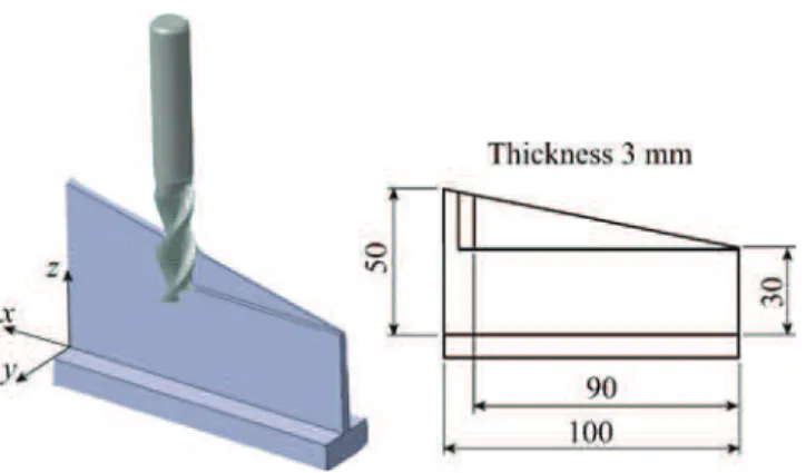
2.1 Design of the test part and cutting conditions
In order to study a real machining case, a special part was designed. The machining process is shown in Fig. 1. The test consists of the progressive increase of axial depth of cut, with a strong effect on the dynamic parameters of material removal and tool position. The evolution of the parameters—axial depth of cut, material removal, dynamic stiffness along the tool path—is significant. The calculation is simplified by the continuity of parameter variation, the
tool being much stiffer than the workpiece and the direction of the deformation being mainly along the y axis.
The down-milling operation consists of an axial depth of cut increasing from 0 to 19 mm. The radial depth of cut is 2 mm.
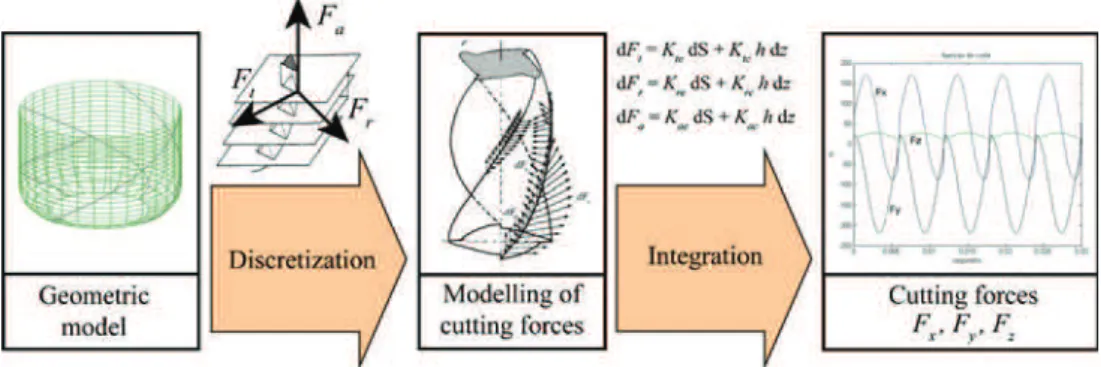
2.2 Milling modelling
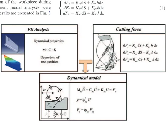
As shown in Fig. 2, the dynamics of the workpiece are
represented following a finite element analysis and the cutting force law is represented by a linear model. The finite element model is updated as the workpiece is machined. These two models are then used in the dynamic model of milling to represent the interaction between the instantaneous cutting force and dynamic displacement. This simulation predicts the stability and surface finish of the machined surface.
The basis of the dynamic milling model is given in [23, 29]. This model was developed to generate precisely the real chip thickness for a flexible workpiece. In this paper, the adaptation of this model is considered to take into account the evolution of the dynamic properties of thin wall during machining. The simulation uses an implicit scheme of time domain integration. In order to simplify the model, the following assumptions have been made:
– Vibrating occurs only along the y axis.
– The cutting zone corresponding to the tip of the tool is neglected.
2.3 Finite element analysis
In order to follow the variation of the workpiece during machining, several finite element modal analyses were carried out every 18 mm. The results are presented in Fig.3
and Table1. The evolution is smooth enough here to allow an interpolation between six calculations with less than 10% error. Following the previous assumptions (see
section 2.2), in this case of modelling, the following
considerations apply:
– Only the displacement along the y axis is significant.
– The dynamic properties of the workpiece change
slowly compared to the variation time of the cutting forces.
– The displacement of the workpiece in the cutting zone
depends only on time and z value, and it is related to the stiffness, mass, damping, frequency and shape of each mode.
– The first three modes represent the dynamic behaviour
of the workpiece.
2.4 Mechanistic model of the cutting law
The mechanistic model gives the cutting force during milling; in this study, the model proposed by Altintas [4] is used. Figure4illustrates this model, which is in three steps: – Calculation of the position of each discretized cutting
edge.
– Corresponding depth of cut associated.
– Total of all the elementary forces.
At each discretized cutting edge, the following cutting law has been applied for tangential, radial and axial force:
dFt¼ KtedS þ Ktchdz dFr¼ KredS þ Krchdz dFa¼ KaedS þ Kachdz 8 < : ð1Þ
with dS the elementary length of the cutting edge, h the width of chip just before cutting and dz is the height of the elementary cutting edge considered. The model requires six coefficients Ktc, Krc, Kac, Kte, Kre and Kae, which are
experimentally determined (see section3). They are mainly associated with the tool, the workpiece material and the presence of cooling fluid. The method used to determine these coefficients is the one proposed by Altintas [4]. 2.5 Modelling of the flexible workpiece and of the milling process
The time domain simulation is resource consuming, and so it is necessary to choose the simplest model at each step of modelling. Due to the high stiffness level of the workpiece in x and z axis, it is possible to consider only the displacements
along the y axis. Because of the milling direction, it is possible to decompose the tool and the workpiece geometry using the steps along z as shown in Fig.5. Thus, the surface is whole, consisting of profiles combined with an elementary height. Lastly, on each plane, the part has only a translating motion following the y direction and the value of the translation is the displacement of the surface point in front of the tool axis.
A modal basis is used to represent workpiece vibrating:
MuU þ CuUþ KuU¼ Fu ð2Þ
where U ¼ uf gi i¼1...n is the modal time function vector
associated with the n modes, Fu is the projected force
vector and M, C and K are the modal matrices associated with mass, damping and stiffness. These matrixes are not constant during machining because of the material removed. They have been calculated by finite element analysis at several points along x during machining; between these points, cubic spline is used for interpolation. According to the previous assumptions, the displacement of the workpiece will be considered as a function of z and x along the machining surface. Displacement of the workpiece is calculated using the modal displacement functions ui and
shape functions φ (obtained by interpolation), as follows:
yðzÞ ¼X
3 i¼1
ui8iðx;zÞ ð3Þ
The occurrence of ploughing is detected by monitoring the instantaneous clearance angle based on the current value of the velocity vector. The ploughing process proposed model is an elementary model increasing a viscous force when negative clearance angle was detected. This added damping produces a reduction of the vibrations in the unstable zone and the clearance angle condition is respected, that reduction means a damping rate over 1,000%. The value of this viscous force—linked to the ploughing effect—was deter-mined by simulation. The influence of the damping rate on the simulation result is more detailed on the discussion section (see section4.4).
Fig. 3 Evolution of natural frequencies during machining
Table 1 Evolution of the dynamic properties of the workpiece Mode Machined length [mm] Frequency [Hz] Damping [%]
1 0 1,209 0.6 18 1,209 0.6 36 1,208 0.6 54 1,211 0.6 72 1,241 0.6 90 1,392 0.6 2 0 2,130 0.5 18 2,164 0.5 36 2,254 0.5 54 2,335 0.5 72 2,319 0.5 90 2,271 0.5 3 0 3,489 0.3 18 3,538 0.3 36 3,464 0.3 54 3,388 0.3 72 3,443 0.3 90 3,288 0.3
Finally, the global cutting force is obtained from the sum of the z-discretized forces, considering only the y axis. The modal project forces are expressed as follows:
Fu;i¼ X z 8iðx;zÞ X n ðdFt;z;ncos ðqz;nÞ þ dFr;z;nsin ðqz;nÞÞ ð4Þ
3 Experimental setup and preliminary tests
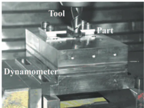
The experimental tests were carried out on a Deckel-Maho DMU60L high-speed milling machine, from 10,000 to 18,000 rpm. The material is aeronautic aluminium Al-6082 T6. The tool is a monolithic carbide end mill, two teeth, 16-mm diameter, helix angle 45°, mounted on a HSK63A holder. The run-out was measured and used in the cutting force simulation to correlate with measurements.
Firstly, in order to obtain the specific coefficients of the tool–material combination, slot-milling experiments were conducted at different feed rates. The cutting conditions are defined in Table 2, and the experimental setup is shown in
Fig. 6. The cutting force measurement was done using a
three component Kistler 9257BA dynamometer. The obtained cutting coefficients are given in Table3.
Secondly, the force modelling was validated with flank
milling tests as seen in Fig. 7. Figure 8 shows the
comparison between the simulated and the experimental
cutting force for this operation. There is a good correlation. The differences between modelling and experiments can be explained by the following arguments:
– When the chip thickness is close to zero, the force is minimal, but the friction contact generates a residual constant force. The modelling gives a near zero force because friction was not taken into account.
– When the chip is maximal, experiments give a higher
force than simulation, probably because static and dynamic deflections were not taken into account in this modelling.
4 Thin-wall milling test and simulations
In this section, the results of the previous section are used for thin-wall milling. First, many tests were done in order to evaluate the stability of the machining. Then various comparisons between modelling and experiment were made. 4.1 Stability analysis
A set of nineteen experimental tests were carried out to evaluate the behaviour of the workpiece during machining
Fig. 4 Illustration of the mech-anistic modelling of the cutting law
Fig. 5 z-Discretization of the surface
and to validate the proposed milling model. The thin walls were down-milled, with axial depth of cut variable along the tool path from 0 to 19 mm, a radial depth of cut of 2 mm and a feed rate of 0.1 mm/tooth. The experimental setup is shown in Fig. 9. The displacement of the cutting zone of the workpiece—during milling—was measured with an eddy current sensor. The acoustic signal of a microphone was also recorded to detect vibration frequen-cies and chatter. The presence of unstable machining, i.e. chatter, is shown in Table 4.
Most of the tests show instability much before machining is completed mainly because there is an increasing axial depth of cut during the operation and different vibrating modes are involved in vibrations of this test part. The proposed milling test is a very unstable machining operation with only two rotating speeds avoiding chatter vibrations in the workpiece, 12,000 and 15,330 rpm.
We have often noted that machinists in industrial context do not hesitate to use the full machine capacities, as much as acceptable surface qualities make it possible. Here, we consider strong tool engagement for thin wall machining in order to test the simulation in a realistic context, as illustrated Table4.
4.2 Frequency vibration
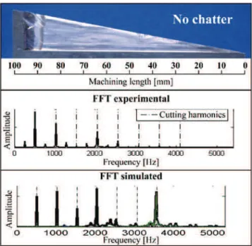
In order to validate the simulation, the results obtained from experimental tests were compared to the simulated data; the dynamic behaviour of the test piece during the machining operation is well described by the milling model according
to the vibration frequency spectrum. Figure 10 shows a
stable machining operation. The main peaks of the vibration spectrum are related to tooth passing frequency and its harmonics, which are forced vibrations. The strong influence of the harmonics can be explained by the interrupted nature of the cutting process with a radial immersion ratio of Ae/D=0.125.
Figure 11 shows the results for a spindle speed of
17,660 rpm. In this case, a chatter problem occurs in the zone between 10 and 20 mm. A peak can be seen in the frequency spectrum at 2,267 Hz, near the natural frequency of mode 2. Other harmonics of the forced vibrations are present, but in this case, the chatter frequency is clearly linked to the second mode of the part.
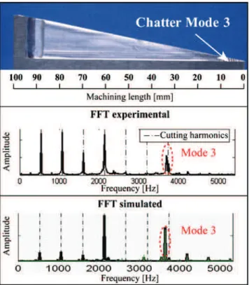
Figure12shows the results for a chatter problem in the zone between 0 and 10 mm; in this case, a peak at 3,627 Hz can be identified near the natural frequency of mode 3; it is also chatter frequency.
The experimental displacement and sound measurements show that the chatter is related to the three vibration modes considered. Moreover, the influence of each mode in the chatter vibrations is related to the x position, and this is clearly influenced by the mode shapes showed in Fig. 3, therefore:
– Mode 3 is the most important factor between 0 and
15 mm.
– Mode 2 is the most important factor between 15 and
25 mm.
– Mixed effects of Mode 2 and Mode 3 can be observed
between 25 and 55 mm.
– Mode 1 is the most important factor in the final stage of machining.
The qualitative results obtained proved to have a useful model due to the fact that the simulations can predict the chatter problems at different zones of the workpiece. The correlation between the spectrum predicted by simulation and the experiment measurement also correspond.
4.3 Displacement vibration
To verify the predictive capabilities of the model, the simulation results were compared to the displacement directly measured during the thin-wall machining.
Figure13shows the behaviour of an unstable case for a spindle speed of 12, 660 rpm. The experimental displace-ment measured during the test and the simulation results can be seen. Both displacements are also sampled at the tooth passing frequency. On the panel (a) (c), chatter cannot be seen clearly because amplitude would be affected by the run-out of the tool. However, on the panel (b) (d)—signal sampled at the tooth passing frequency—different vibrating behaviour is observed.
Fig. 6 Preliminary experimental setup, for slotting test Table 2 Cutting condition used for the specific coefficients identification
Cutting conditions Values
Cutting speed 502 m/min (10,000 rpm) Feed rate 0.03; 0.05; 0.07; 0.12 mm/tooth Axial depth of cut (Ap) 4 mm
Between x = 0 and 25 mm, both experimental and simulated results present an amplitude of about 0.4 mm. For these stable conditions (forced vibration), the curve of the panel (b) (d) is very smooth.
In contrast, between x=25 and 45 mm, there is a difference between the predicted amplitude and the mea-sured amplitude. However, from a qualitative point of view, the phenomenon is detected by simulation. On the displacement sampled at the tooth passing frequency— panel (b) (d)—the curve shows more peaks and large variations over short periods of time, characteristic of unstable cutting condition with chatter. The surface finish and the marks present on the piece can confirm the machining area in which there has been instability during the process detected in this case between 25 and 45 mm on the machined length.
Between x=45 and 75 mm, both the simulation and the experiment are coherent. Stable cutting conditions are again present in this area, with smooth evolution of the sampled displacement.
Finally, between x=75 and 80 mm, different result appears between experiment and simulation. The large shift in the experimental data is linked to the stoppage of the tool speed; this stoppage implies a static movement of the part of about 1.5 mm. This phenomenon is not taken into account in modelling.
In conclusion, the trends discussed above can be observed both in the experimental signals and in the simulations, although the frequency spectrums of the peak values are comparable. Moreover, the experimental ampli-tude and the simulated ampliampli-tude are significantly different in unstable areas, while for stable cutting condition the vibration amplitudes are comparable, as shown in Fig.13.
4.4 Discussion
A chatter model, developed and verified for several years [10, 21], was used in this study. Here, this model was applied on the milling of a flexible thin-wall workpiece with a large cutting tool engagement where chatter is a major problem that is very difficult to avoid.
The simulation results were compared with experimental tests. The dynamic behaviour of the workpiece during machining is very well described by the simulation according to the vibration frequency spectrum. For this qualitative aspect, the simulations match the experiments well. Regarding vibratory displacement, the experimental and simulated results are significantly different for the unstable cases, while for stable areas the amplitudes are
comparable, as shown in Fig. 13. The discrepancies
between simulated and experimental displacement can be observed for strong chatter cutting conditions. The correla-tions, although satisfactory, are actually not as good as those usually shown for single degree of freedom massive workpiece. The reproducibility of the machining test, the validity of the discretization parameters (spatially and temporally) and the robustness of the modal shape used have been confirmed. At present, it is not clear what causes these discrepancies. Possible reasons could be: the linear cutting law and the effect of the process damping.
For low chip thickness, it is difficult to consider direct proportionality between the chips and cutting forces— linear cutting law. A non-linear cutting law would be more efficient, but it would be necessary to develop a new method for the reliable identification of the cutting coefficients [30].
Process damping is often caused by the contact on the clearance face due to the vibration of the workpiece [22].
Fig. 8 Simulated and measured forces: side milling, Ap=17.5 mm, Ae= 2 mm, fz=0.12 mm/tooth, N=5,000 rpm
Fig. 7 Experimental setup for testing the cutting law, in flank milling
Ktc[MPa] Krc[MPa] Kac[MPa] Kte[MPa] Kre[MPa] Kae[MPa]
631 99 273 13 10 2.8
Table 3 Specific cutting coeffi-cient identified for Al-6082 T6
This ploughing effect increases the damping of the process, and the machining becomes more stable than the simulation [31]. In this way, other complementary simulations were made with different ploughing force models. The ploughing process model was an elementary model increasing the damping of the system when negative clearance angle was detected. The fact that the ploughing effect occurs in only during very short periods (1% to 10% of the time of passage of tools) led us to concentrate on its modelling study. Indeed, it shows both by simulation and experiment that thin walls are very sensitive to the cutting and ploughing forces that can virtually immobilize the thin-walled or restart by one single tooth contact, unlike what happens on parts with higher inertia. The ploughing force is modelled by a viscous force, which allows an important
robustness during the numerical integration. In addition, it should be noted that if one considers a quasi-zero damping, the system is always very unstable. On the other hand, with a very high damping, although there would be more energy dissipation, the ploughing model becomes a simple contact, and again the system is always very unstable. The modelling takes into account the spatial extent on the tool
Fig. 11 Results comparison for chatter machining at 17,660 rpm. Spectrum between 9.6 and 13.6 mm
Fig. 10 Results comparison for chatter free machining at 15,330 rpm. Spectrum between 28.7 and 32.7 mm
Fig. 9 Experimental setup for thin-wall milling
Table 4 Stability of the cutting tests
Spindle speed [rpm] Stability
12,000 No chatter 12,330 Chatter 12,660 Chatter 13,000 Chatter 13,330 Chatter 13,660 Chatter 14,000 Chatter 14,330 Chatter 14,660 Chatter 15,000 Chatter 15,330 No chatter 15,660 Chatter 16,000 Chatter 16,330 Chatter 16,660 Chatter 17,000 Chatter 17,330 Chatter 17,660 Chatter 18,000 Chatter
and the local intensity at each point, making a fairly complex analysis to be undertaken. To check the consistency of the model, we have tested several simplifications in order to avoid the actual extent or intensity of the damping, but with standard values (either average or maximum). We have checked the effect of many changes on the ploughing model, we cannot detail here all. We will simply give the main results of these investigations. By simplifying more or less the ploughing model, we have obtained similar results with the nominal case presented in this article. It should be noted that the use of a higher damping need a smaller discretization time step because of the interaction time of the contacts, getting closer and closer to solid contact model. Practically, it is difficult to determine the ploughing modelling that would provide the desired damping.
5 Conclusions
This paper presents a study of stability of the cutting process for the machining of thin-walled parts. A specific model of flexible workpiece was developed to simulate the machining of such pieces. The instantaneous clearance angle is taken into account all along the cutting edges in order to accurately model the ploughing effect. The variations of the dynamical parameters are computed by finite element analysis in order to take into account the removal material and the cutting edge position. This modelling allows to predict the part
dynamical properties without having excessive computing times. With this data, the dynamic modelling of milling is made by time domain simulation, using modal decomposi-tion. This approach is novel for thin-wall machining because previous simulations were made without real machining to compare with.
The comparison between experiment and simulation show very good correlation for the cutting force prediction both on shape than on the value. The results show that simulation was able to predict realistic chatter frequency, which was very helpful for the improvement of the thin-wall milling. The milling model shows good agreement with experimental data when the vibration amplitude is low and the machining operation is chatter free. On the contrary, it is highlighted that the prediction of amplitudes in case of unstable milling is very complex. The simulation results provide only qualitative information about the modal vibrations for operations with high vibration amplitudes. This could be explained by the influence of ploughing effect. Such phenomenon is well-known to act like damp-ing and the use of a quasi-steady-state force model to simulate machining with high vibration levels seems to be
Fig. 13 Displacement comparison for chatter machining at 12,666 rpm Fig. 12 Results comparison for chatter machining at 16,000 rpm.
inadequate, whatever be tested to improve the simulation parameters considered here.
The modelling widely robust for vibration tools or more massive pieces seems to have reached its limits on this case. Therefore, the improvement in the simulation of thin-walled components machining needs development of cutting force models including contact modelization and ploughing due to the variation of the clearance angle during machining.
Acknowledgements This work was supported by the Basque Country Government, by the CIC MARGUNE developed under the ETORTEK program; by the Spanish Ministry of Science and Technology; by the project OPTITOOL, MICYT DPI2002-04167-C02-01 and by the French Region Midi-Pyrénées Project ‘Complex workpiece machining in aeronautical context’.
References
1. Tobias SA, Fishwick W (1958) Theory of regenerative machine tool chatter. Engineer 205:199–203, 238–239
2. Tlusty J, Polácek M (1963) The stability of the machine tool against self-exited vibration in machining, Proceedings of the International Research in Production Engineering Conference. ASME, Pittsburgh, pp 465–474
3. Altintas Y, Budak E (1995) Analytical prediction of stability lobes in milling. Ann CIRP 44:357–362
4. Altintas Y (2000) Manufacturing automation. Cambridge Univer-sity, Cambridge
5. Bayly PV, Halley JE, Mann BP, Davies MA (2003) Stability of interrupted cutting by temporal finite element analysis. Trans ASME J Manuf Sci Eng 125:220–225
6. Insperger T, Stépán G (2004) Uptaded semi-discretization method for periodic delay-differential equations with discrete delay. Int J Numer Meth Eng 61:117–141
7. Insperger T, Stépán G, Turi J (2008) On the higher-order semi-discretizations for periodic delayed systems. J Sound Vib 313:334–341 8. Davies MA, Pratt JR, Dutterer B, Burns TJ (2002) Stability prediction for low radial immersion milling. Trans ASME J Manuf Sci Eng 124:217–225
9. Insperger Y, Mann BP, Stépán G, Bayly PV (2003) Stability of up-milling and down-up-milling, Part 1: alternative analytical methods. Int J Mach Tools Manuf 43:25–34
10. Campomanes ML, Altintas Y (2003) An improved time domain simulation for dynamic milling at small radial immersions. Trans ASME J Manuf Sci Eng 125:416–422
11. Lapujoulade F, Mabrouki T, Raïssi K (2002) Prédiction du comportement vibratoire du fraisage latéral de finition des pièces à parois minces. Mec Ind 3:403–418
12. Thevenot V, Arnaud L, Dessein G, Cazenave-Larroche G (2006) Influence of material removal on dynamic behavior of thin walled structure in peripheral milling. Mach Sci Technol 10:275–287 13. Thevenot V, Arnaud L, Dessein G, Cazenave-Larroche G (2006)
Integration of dynamic behaviour in stability lobes method: 3D
lobes construction and application to thin walled structure milling. Int J Adv Manuf Technol 27:638–644
14. Seguy S, Campa FJ, López de Lacalle LN, Arnaud L, Dessein G, Aramendi G (2008) Toolpath dependent stability lobes for the milling of thin-walled parts. Int J Mach Machinabil Mater 4:377– 392
15. Bravo U, Altuzarra O, López de Lacalle LN, Sánchez JA, Campa FJ (2005) Stability limits of milling considering the flexibily of the workpiece and the machine. Int J Mach Tools Manuf 45:1669– 1680
16. Herranz S, Campa FJ, López de Lacalle LN, Rivero A, Lamikiz A, Ukar E, Sánchez JA, Bravo U (2005) The milling of airframe components with low rigidity: a general approach to avoid static and dynamic problems. P I Mech Eng B J Eng Manuf 219:789– 801
17. Kline WA, Devor RE, Lindberg JR (1982) The prediction of cutting forces in end milling with application to cornering cuts. Int J Mach Tool Des Res 22:7–22
18. Engin S, Altintas Y (2001) Mechanics and dynamics of general milling cutters, part I: helical end mills. Int J Mach Tools Manuf 41:2195–2212
19. Tlusty J, Ismail F (1981) Basic non-linearity in machining chatter. Ann CIRP 30:299–304
20. Tlusty J (1986) Dynamics of high speed milling. Trans ASME J Eng Ind 108:59–67
21. Smith S, Tlusty J (1993) Efficient simulation programs for chatter in milling. Ann CIRP 42:463–466
22. Montgomery D, Altintas Y (1991) Mechanism of cutting force and surface generation in dynamic milling. Trans ASME J Eng Ind 113:160–168
23. Peigné G, Paris H, Brissaud D (2003) A model of milled surface generation for time domain simulation of high-speed cutting. P I Mech Eng B J Eng Manuf 217:919–930
24. Surmann T, Enk D (2007) Simulation of milling tool vibration trajectories along changing engagement conditions. Int J Mach Tools Manuf 47:1442–1448
25. Altintas Y, Montgomery D, Budak E (1992) Dynamic peripheral milling of flexible structures. Trans ASME J Eng Ind 114:137– 145
26. Li H, Shin YC (2006) A comprehensive dynamic end milling simulation model. Trans ASME J Manuf Sci Eng 128:86–95 27. Lorong P, Coffignal G, Cohen-Assouline S (2008) Simulation du
comportement dynamique d’un système usinant: modélisation de l’interaction outil/matière en présence d’une pièce flexible. Mec Ind 9:117–124
28. Seguy S, Dessein G, Arnaud L (2008) Surface roughness variation of thin wall milling, related to modal interactions. Int J Mach Tools Manuf 48:261–274
29. Gonzalo O, Peigné G, Gonzalez D (2006) High speed machining simulation of thin-walled components, 5th International Confer-ence on High Speed Machining. Metz, France
30. Paris H, Brissaud D, Gouskov A (2007) A more realistic cutting force model at uncut chip thickness close to zero. Ann CIRP 56:415–418
31. Turner S, Merdol D, Altintas Y, Ridgway K (2007) Modelling of the stability of variable helix end mills. Int J Mach Tools Manuf 47:1410–1416
![Table 1 Evolution of the dynamic properties of the workpiece Mode Machined length [mm] Frequency [Hz] Damping [%]](https://thumb-eu.123doks.com/thumbv2/123doknet/3675001.108827/5.892.77.433.723.1106/table-evolution-dynamic-properties-workpiece-machined-frequency-damping.webp)