Open Archive Toulouse Archive Ouverte (OATAO)
OATAO is an open access repository that collects the work of Toulouse researchers and makes it freely available over the web where possible.
This is an author-deposited version published in: http://oatao.univ-toulouse.fr/
Eprints ID : 2949
To link to this article :
URL : http://dx.doi.org/10.1016/j.jallcom.2008.04.014
To cite this version : Massot, Laurent and Chamelot, Pierre and Winterton, Peter and Taxil , Pierre ( 2009) Preparation of tantalum carbide layers on carbon using the metalliding process. Journal of Alloys and Compounds, vol. 471 (n°1-2). pp. 561-566. ISSN 0925-8388
Any correspondence concerning this service should be sent to the repository administrator: [email protected]
Preparation of tantalum carbide layers on carbon
using the metalliding process
L. Massot (1)*, P. Chamelot(1), P. Winterton(2) and P. Taxil(1) (1)
Laboratoire de Génie Chimique UMR 5503, Département Procédés Electrochimiques, Université Paul Sabatier, 31062 Toulouse Cedex 9, France.
(2)
UFR Langues vivantes, Université Paul Sabatier, 31062 Toulouse Cedex 9, France.
* corresponding author: MASSOT Laurent Tel: +33 5 61 55 81 94 Fax: +33 5 61 55 61 39 [email protected]
ABSTRACT
This work concerns the preparation of tantalum carbide films on carbon based substrates using the metalliding process in LiF-NaF molten medium (60-40% mol.), containing tantalum heptafluorotantalate ions TaF72-, in the 800-900 °C temperature range. The process uses a metalliding cell symbolized as: (+) C, TaCx/LiF-NaF-K2TaF7/Ta (-) involving the dissolution of Ta at the anode and the reduction of Ta ions in TaCx at the cathode. The experiments of this process were performed with different carbon substrates as cathodic material: graphite, glassy carbon and carbon braid. Samples analysis (SEM-EDS and XRD) after metalliding showed the formation of tantalum carbides (TaC and Ta2C) at the surface of the substrate at a relatively low temperature. A kinetic study, based on the control of the cathodic reaction by the intermetallic diffusion, allowed the diffusion parameters, such as Ta-C diffusion coefficient, to be determined at several temperatures. Furthermore, the results are shown to be independent of the type of carbon substrate.
KEY WORDS
Tantalum carbide, metalliding, intermetallic diffusion, molten fluorides, carbon materials
1/ Introduction
This article describes an unexpectedly simple process for coating carbon matrices by metallic carbides such as tantalum carbides. Obtaining these compounds by conventional methods – mixing the fused components – would be extremely problematic owing to the
very high melting points of the compounds involved (C: 3445°C, Ta: 3020°C, TaC: 3985°C). The process described here takes place at about 800°C and involves using a metalliding cell where the electrolyte is an alkali fluoride mixture, the anode is tantalum metal, which dissolves in the bath, and the cathode is the carbon substrate, which reacts with Ta ions to give TaC and Ta2C. The system works spontaneously, owing to the negative Gibbs Energy of the carbides, and rapidly, due to the solid diffusion occurring within the carbon matrix, fast enough for the substrate surface to be composed of tantalum carbides rather than of the metal itself. The process takes advantage of the ability of the molten salt mixture to wet all the pores of the substrate, so the whole outer surface of the carbon matrix is covered with tantalum carbide. The article reports a kinetic study of the growth of the carbide layer within the substrate, based on Danckwerts' theory of solid diffusion and Crank’s mathematical model of mass transfer within a diffusion layer. The study shows that the diffusion rate is not influenced by the matrix structure and leads to the calculation of the intermetallic diffusion coefficient for the Ta/C system at various
temperatures.
Carbon is resistant to highly corrosive media in industrial processes, for example to cryolite at 900°C for the preparation of aluminium [1]; nevertheless, the porosity of carbon
adversely affects its mechanical surface properties; coating a carbon matrix with tantalum carbide would greatly improve these properties. Chemical reduction by carbon (carbo-reduction) of a gaseous (TaCl5) [2] or solid (Ta2O5) [3;4] precursor at the surface of a carbon-based material could be proposed but presents the disadvantage of forming non-uniform layers of carbide and also requires temperatures of between 1500 and 2500°C. In
this article we propose an electrochemical route, using a cell where Ta ions are released by the anode reaction and reduced to yield carbide at the surface of the cathodic substrate. The process, called metalliding, can only be achieved if the electrolyte is an alkali fluoride mixture and the temperature is about 700-900°C. In the present paper, we show that this process not only avoids the disadvantages of carbo-reduction but also protects the porous surface structure of the carbon material. This work follows a recent study where we prepared tantalum carbide layers on steel by stepwise electrodeposition of tantalum in molten fluorides at 800-900°C, then carbon on tantalum with further reactions of electrodeposited carbon and the tantalum [5]. This work revealed the high reactivity of carbon towards tantalum in the temperature range studied, thus suggesting that, based on this reactivity, the process should be a success.
2/ Experimental
The cell was a vitreous carbon crucible placed in a cylindrical vessel made of refractory steel and closed by a stainless steel lid cooled by circulating water [6;7] The inside of the walls was protected against fluoride vapours by a graphite liner. The
experiments were performed under an inert argon atmosphere (less than 5 ppm O2, Linde), previously dehydrated and deoxygenated using a purification cartridge (Air Liquide). The cell was heated using a programmable furnace and the temperatures were measured using a chromel-alumel thermocouple.
The electrolytic bath consisted of a eutectic LiF/NaF (Merck 99.9%) mixture (60/40 molar %). It was initially dehydrated by heating under vacuum (10-2 mmHg) to its melting point (650°C) for 48 hours. Tantalum ions were introduced into the bath in the form of potassium heptafluorotantalate K2TaF7 (Merck 99.9%) pellets. The concentration of K2TaF7 in the bath was 5 mass% (0.127 mol/kg).
As working electrode, three carbon materials expected to form carbides by surface reaction with tantalum were used: graphite (Carbone Lorraine), glassy carbon (V25 quality, SGL Carbon) and carbon braid (Sepcarb). The surface area of the working electrode was determined after each experiment by measuring the immersion depth in the bath.
The auxiliary electrode was a tantalum plate (50*10*1 mm) with a large surface area (6 cm²) was immersed in the bath.
The potentials were referred to a tantalum wire (1 mm diameter) immersed in the molten electrolyte, acting as a comparison electrode TaF72-/Ta [6].
All the electrochemical studies and the electrolysis were performed with an Autolab PGSTAT 30 potentiostat / galvanostat controlled by a computer using the research software Autolab 4.9.
The layers obtained during the experiments were observed using Scanning Electron Microscopy (SEM, Leo 435 VP) and the composition of these layers was determined by X-Ray Diffraction (XRD, Seifert).
3/ Results and discussion
3-1/ The metalliding process
Metalliding is the production of alloys or surface compounds by electrodeposition with no current source in the electric circuit. It was developed by N.C. Cook of General Electric in the sixties and seventies [8-11] to coat common metals with layers of alloys having
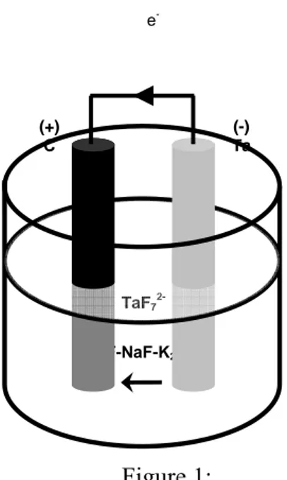
particularly attractive properties such as beryllides, silicides or yttrides. With an electrolyte composed of a mixture of alkali metal fluorides fused by heating to 800 – 1000°C, the process generates its own electricity. The anode is an electropositive metal (R) (here tantalum) and the cathode a noble element (N) (here carbon). An electrical connection is made between the two electrodes outside the cell as shown in figure 1.
The high temperature of the molten salt bath activates the reaction between the metal of the cathode and the ions of the anode metal giving rise to an intermetallic compound and accounting for the permanent difference in chemical potential between the two electrodes. The reactions giving rise to this "battery effect" can be written as follows:
Anode: R Rn+ + ne (1) Cathode: Rn+ + ne + yN RNy (2) Overall: R + yN RNy (3)
The system works if intermetallic diffusion is fast enough for RNy to remain at the noble metal surface (N) and if reaction (3) remains thermodynamically spontaneous.
The originality of the metalliding process is the uniform production of a thermodynamically stable product: the electrolytic deposition does not require a current source to generate a voltage at the cathode.
The process has been adapted by various researchers, including Weppner and Huggins for the preparation of Al-Li, Bi-Li and Sb-Li alloys [12-14] used as anodes in lithium batteries, Mottot and Picard for the preparation of La-Ni supermagnets [15] and Goodshall for the preparation of alloys on a nickel substrate [16].
Our laboratory has used this process to coat nickel with Ta-Ni [17] and Nb-Ni [18] alloys, which show remarkable resistance to corrosion by concentrated acids [19].
More recently, we used metalliding to produce Nd-Ni and Nd-Cu alloys for their magnetic properties [20], and for their ability to adsorb and store hydrogen for use in fuel cells [21]. In each of these applications, this relatively low-temperature process has straightforwardly yielded novel materials, difficult to obtain with conventional methods.
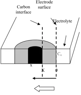
Work we have done [17-19] shows that the process enables the preparation of alloy coatings of uniform thickness covering the entire cathode whatever its shape. This can be explained by the fact that the reaction and the process of alloy formation are controlled by intermetallic diffusion in the bulk of the cathode material [17]. Figure 2 presents the growth scheme of the alloy coating arising from the flux of diffusing species J, as defined by Fick's law, between the surface of the cathode where the anode metal concentration is maximum (Co) and the interface with the substrate where it is minimum (Cx):
J = -D (δC/δx)X (4)
The thickening of the alloy deposit is therefore ensured by mass transfer in the alloy coating of the metallic species resulting from the discharge of the Rn+ ions. The current density of the metalliding cell can therefore be written:
i = -nF D (δC/δx)X (5)
In the stationary state, as the values of Co and Cx and the mean composition of the diffusion layer Cm, are invariable as x increases, from equation (5), it is seen that the current must decrease. The mechanism of alloy layer growth follows the model reported by Danckwerts for the formation of a coating of compound AB, on a surface made of A, from the
deposition of B and the interdiffusion of the two elements in the layer [22]. The model calculates the progression of interface X into the bulk of the substrate using the equation:
X = Kt1/2 (6)
where K is the rate constant of growth for the system. Equation (5) is similar to Cottrell's law for a reaction controlled by the flux of ions transferred from the liquid phase to the adjacent cathode when an overvoltage is applied to the electrode. Note that in this case, the influence of the hydrodynamic state of the electrolyte on the flux generates surface
irregularities. These are avoided when deposition is driven by the metalliding process.
3-2/ Application to the Ta/C system
3-2-1/ Preliminary discussion
The process can be applied to making protective layers of tantalum carbide on carbon-containing materials. Carbon resists corrosion well but has poor mechanical resistance due
to its crystal structure which includes spaces making it generally porous and brittle. The specific surface area (SSA) of most carbon materials is then very high, enabling the
penetration of chemicals which can amplify degradation phenomena to unacceptable levels. The present study describes the application of the metalliding process to the preparation of layers of tantalum carbide on the surface of carbon materials with the purpose of enhancing their mechanical and corrosion resistance [23]. Preventing penetration from occurring requires the pores to be sealed to form a compact superficial layer made of a substance at least as resistant to corrosion as carbon, such as tantalum carbide.
The phase diagram of the binary tantalum-carbon system demonstrates the occurrence of two compounds [24]: TaC and Ta2C which, at 800°C, have Gibbs energies of -140.9 kJ/mol and -209.6 kJ/mol respectively [25]. These values indicate that both TaC and Ta2C can be prepared by metalliding.
The cell used to coat the carbon surfaces with tantalum carbide was composed of a glassy carbon crucible containing the molten salt and the two electrodes:
- for the carbon-based cathode, we experimented with graphite, carbon braid (Sepcarb) and glassy carbon, all having different crystallographic structures and porosities,
- the anode was made of tantalum rod.
The cell was placed in a refractory steel chamber sealed with a water-cooled lid. The inner walls of the chamber were protected from the electrolyte vapours by a graphite lining (as detailed in [26]). The electrolyte was composed of a mixture of fluorides (LiF and NaF) containing a small quantity of potassium heptafluorotantalate (K2TaF7), a salt of the metal to be transferred (tantalum). The galvanic cell can be symbolised as:
The current is generated by the exchange of electrons involved in the electrode reaction corresponding to equations (1) and (2):
Ta + 7 F- TaF72- + 5 e- (8) TaF72- + x C + 5 e- TaCx + 7 F- (9)
The overall reaction produces carbide:
Ta + xC TaCx (10)
The choice of the fluorides is firstly the result of their high stability and of their ability to complex tantalum ions (9). This situation was reported by Union Carbide researchers Senderoff and Mellors [27] who were the first to grow deposits of refractory metals such as tantalum in molten fluorides. The use of fluorides as electrolyte implies that all traces of oxygen-containing compounds must be removed to avoid secondary reactions occurring with the oxide ions. So, as a preliminary treatment, we proceeded by melting the electrolyte under vacuum and purging with argon. Production of the alloy layer involved operating the cell at around 900°C; the current generated between the electrodes was measured, the cathodes were weighed before and after each run while the layers of alloy formed were observed under the scanning electron microscope (SEM) and analysed by X-ray diffraction (XRD).
Tantalum carbide was prepared using the metalliding cell run at 900°C for about 20 hours with a graphite rod as cathode. Figure 3 reports the variation in the current produced by the cell decreasing logarithmically as indicated by equation (5) and demonstrated by equation (13) presented below.
A micrograph of the resulting rod (fig 4a) shows a thick (about 300 µm) uniform layer of a light coloured material. On analysis by XRD (fig 5) it was found to contain both TaC and Ta2C. The analysis suggests that the compound with the larger proportion of tantalum, Ta2C, is the majority product - it is more stable - but that the large excess of carbon caused by contact with the carbon matrix pushes the reaction equilibrium towards TaC. The
presence of Ta2C, which is harder and more corrosion resistant than TaC [28], enhances the protection afforded by the layer. Figure 4a and the enlargement in 4b illustrate the presence of tantalum carbide in the grain boundaries of the carbon matrix. Metalliding will therefore protect the carbon against inter-grain corrosion. Similar experiments using other forms of carbon confirmed that metalliding led to the production of a thick layer of tantalum carbide penetrating the porous structure of the material.
Figure 6 shows for instance, a section of metallided carbon braid where each of the fibres in the braid has a protective carbide sheath.
3-2-3/ Kinetic study and Ta/C intermetallic diffusion coefficient
A kinetic study verified the reaction mechanism proposed above and determined the growth kinetics of the carbide layer during the carbon surface treatment.
We then calculated the rate constant for the growth of the alloy layer. For a given temperature, the thickness of the compact layer at the surface of the carbon rod is given versus time by equation (6). Owing to intermetallic diffusion, the thickness, X, is taken as proportional to the weight gain of the cathode and is calculated by:
(11)
where Δm is the weight gain of the cathode, W is the mass fraction of Ta in Ta2C (the tantalum carbide actually formed) i.e. 0.968, and ρ is the density of Ta2C. The specific surface area of the cathode in contact with the electrolyte was calculated by multiplying the simple geometric surface area of the submerged part of the cathode by the porosity factor of the carbon material used.
The weight gain per unit cathode surface area is plotted versus the square root of the treatment time in figure 7 for the three forms of carbon studied; the temperature was the same (850°C) throughout. In figure 8 the temperature is varied for a single carbon form, graphite.
The graphs are linear, confirming the validity of equation (6), using equation (11). The slopes of the lines then give the rate constant for a given material. The weight gain per unit surface area was calculated with respect to the specific surface area. Table 1 reports the
S.W.ρ Δm X=
values of the kinetic constant K, and the figures used to obtain them, for the three materials at 850°C.
The slopes of the plots of Δm/SSA versus t1/2 are identical, indicating that the diffusion kinetics in the solid phase are independent of the crystallographic structure of the carbon material.
The coefficient of diffusion of tantalum into the carbon matrix can be determined from the rate constant defined above and the equation giving the current produced by the metalliding cell. The calculation was originally developed by our laboratory [18] using the values of the current produced by the metalliding cell at 850°C: figure 3 gives an example of the currents obtained.
The mathematical treatment of mass transfer by diffusion was done using Crank's model [29]. The following relationship was obtained for the concentration of the tantalum diffusing species: Dt 2 X erfc C C= o (12)
Where Co is the concentration at the surface of the electrode, i.e. the tantalum concentration in compound Ta2C which forms at the surface, X is the position in the diffusion layer, D the coefficient of intermetallic diffusion and erfc is a function often used in transfer calculations.
πt D 5FC Dt 2 X exp i o 2 ⎟ ⎟ ⎠ ⎞ ⎜ ⎜ ⎝ ⎛ ⎥ ⎦ ⎤ ⎢ ⎣ ⎡ − = (13)
Taking into account eq (6) where X is proportional to t ½ and eq (13) where i is proportional to t -½ the slope (p) of the plots of i versus the reciprocal of root t can be expressed as: ) exp( π D 5FC p= o −α2 (14) where: D K 2 1 = α (15)
Combining (14) and (15) we obtain:
K 5FC π 2p α ) α exp( o 2 = − (16)
Resolving equation (16) we obtain α, and hence D using equation (15) with the values of K determined with the method outlined above. The values of K, α and D obtained for graphite are reported in Table 2 for the three temperatures studied: 850, 900 and 950°C. The values of D follow the Arrhenius equation and can be written as follows:
T 52.27 -exp 10 . 45 . 3 D 15 ⎟ ⎠ ⎞ ⎜ ⎝ ⎛ = − (17)
4/ Conclusions
The major finding of our work is that carbon, an extremely useful material in diverse applications, can be given a coating of highly resistant tantalum/carbon alloy in surprisingly mild conditions considering the very high melting points of tantalum/carbon alloys. It enables the major drawbacks of carbon, its brittleness and porosity, to be overcome. The process, which is based on the solid diffusion of an electrochemically deposited metal (tantalum) into the bulk of another quasi-metal (carbon) occurs spontaneously to yield a thermodynamically stable product which transforms the porous surface of the carbon material into a tightly sealed, highly resistant layer of tantalum carbide. The most obvious applications will be the protection of carbon electrodes and of carbon linings of nuclear reactors which are prone to surface crumbling and erosion. The concept will certainly lend itself to the formation of other attractive refractory metal carbides (e.g. Nb, Mo and W) but also to other metallides such as silicides. The process we report could avoid some rather unfortunate consequences of erosion in key applications.
Acknowledgements: The authors thank the CEA for their cooperation and their financial participation in this work.
References
[1] J. Thonstad, Aluminium Electrolysis, Fundamentals Of The Hall-Héroult Process, 3rd edition, Aluminium-Verlag, Dusseldorf, 2001.
[2] I.L. Sinani, R.K. Chuzko, Y.P. Chernikov, Inorg. Mater. 31 (1995) 612-616.
[3] N.A. Hassine, J.G.P. Binner, T.E. Cross, Int. J. Refract. Met. H., 13 (1995) 353-358. [4] Y.J. Chen, J.B. Li, Q.M. Wei, H.Z. Zhai, J. Cryst. Growth 224 (2001)2 44-250. [5] L. Massot, P. Chamelot, P. Taxil, J. All. Comp. 424 (2006) 199-203.
[6] P. Chamelot, P. Taxil, B. Lafage, Electrochim. Acta 39 (1994) 2571-2578.
[7] L. Massot, P. Chamelot, F. Bouyer, P. Taxil, Electrochim. Acta 48 (2003) 465-471. [8] D.K. Hanink US Patents 2,970,091 (1961) "Method of alloying Aluminium and Copper"; N.C. Cook US Patents 3,024,176 (1962); 3,024,177 (1966); 3,232,853 (1966) "Corrosion resistance coatings".
[9] Cook, N.C., Sci. Am., 221 (1969) 224-242.
[10] B.A. Fosnocht, Manuf. Supercond. Mater., Proc. Int. Conf. (1977) 196-201. [11] J.C. Withers, J.E. Perry, B.A. Fosnocht, Tech. of metals research, (1972) 203-227. [12] W. Weppner, R.A. Huggins, J. Electrochem. Soc. 124 (1977) 1569-1578.
[13] W. Weppner, R.A. Huggins, J. Electrochem. Soc. 125 (1978) 7-14.
[14] G.J. Wen, B.A. Boukamp, R.A. Huggins, J. Electrochem. Soc. 126 (1979) 2258-2266.
[15] G.S. Picard, Y.E. Mottot, B.L. Tremillon, Proc. - Electrochemical Society 84 (1984) 585-602.
[17] P. Taxil, Z.Y. Qiao, J. App. Electrochem. 15 (1985) 947-952. [18] P. Taxil, J. Less-common Met. 113 (1985) 89-101.
[19] P. Taxil, J. Mahenc, Corros. Sci. 21 (1981) 31-40.
[20] C. Nourry, L. Massot, P. Chamelot, P. Taxil,J. New Mat. Elect. Sys. 10 (2007) 117-122.
[21] Y.D. He, R. Z. Zhu, W. Q. Zhang, W. P. Yu, X. Q. Ma, W. M. Deng, Mat. Sci. Eng. A-Struct.123 (1990) 117-122.
[22] P.V. Danckwerts, T. Faraday Soc. 46 (1950) 701-712.
[23] L. Massot, PhD Thesis, University of Toulouse, France (2002).
[24] Binary Alloy Phase Diagrams, Second Edition ASM International (1996). [25] I. Barin, O. Knacke, Thermochemical Properties Of Inorganic Substances, Ed. Springer-verlag, Berlin, 1973.
[26] L. Massot, P. Chamelot, F. Bouyer, P. Taxil, Electrochim. Acta 47 (2002) 1949-1957.
[27] S. Senderoff, G.W. Mellors, Science, 153 (1966) 1475-1481.
[28] G.E. Gadomski, K.E. Dodson, H. Bronson, Actinide Processing. Methods and Materials, Mishra B. Ed., 1994.
[29] J. Crank, The Mathematics of Diffusion, Oxford University Press, London, 1967.
Figure Legends
Figure 1:
Scheme of a galvanic cell for metalliding with a carbon cathode and a tantalum anode. Temperature range: 700-950°C.
Figure 2:
Scheme of Ta solid-state mass transfer within the intermatallic diffusion layer.
Figure 3:
Current-time transients of the Ta/C system at 900°C, showing the decrease of the galvanic current versus the time.
Figure 4a:
Micrograph of the graphite electrode after 22h of contact at 900°C. Magnification: 20x, showing the regular thickness of the Ta/C interdiffusion layer obtained.
Figure 4b:
Enlargement of micrograph 4a. Magnification: 500x.
Figure 5:
Figure 6:
SEM micrographs of carbon braid after 22h of treatment at 900°C. Magnification: 10 000x. In the outer portion of the braid the Ta/C layer covers the whole surface of the fibers
Figure 7:
Mass of tantalum diffusing into the substrate versus the square root of the contact time at 850°C for three carbon substrates.
Figure 8:
Mass of tantalum diffusing in the substrate versus the square root of the contact time on the graphite electrode for various temperatures.
Table 1:
Determination of the kinetic constant of tantalum - carbon interdiffusion for three carbon substrates. (SSA = Specific Surface Area)
Table 2:
Figure 1: e -LiF-NaF-K2TaF7 TaF7 2-(+) C (-) Ta
Figure 2: Electrolyte Electrode surface Carbon interface x X 0 Co Cm CX
Figure 4a
Figure 4b
0 1000 2000 3000 4000 5000 6000 7000 8000 9000 20 30 40 50 60 70 80 2 θ In te n s iy ( A .U .) + + + + * : C +: TaC o : Ta2C o o o o o o o o * * * * Figure 5:
Figure 6:
Carbon material Density ρ in g.cm-3 Porosity factor: SSA/geometric area Slope Δm/SSA in g.cm-2 Kinetic constant K in cm2/s Graphite 2.25 10.8 1.99 10-5 1.8 10-12 Vitreous carbon 1.4 2.25 Sepcarb braid 1.3-1.8 16.1 Table 1:
Temperature T in °C Slope p in A.cm-2.s1/2 α D in cm².sDiffusion -1 850 3.275 10-4 1.75 1.47 10-13 900 4.370 10-4 1.98 1.63 10-12 950 6.565 10-4 2.04 6.13 10-12 Table 2: