HAL Id: hal-02975020
https://hal.archives-ouvertes.fr/hal-02975020
Submitted on 22 Oct 2020
HAL is a multi-disciplinary open access
archive for the deposit and dissemination of
sci-entific research documents, whether they are
pub-lished or not. The documents may come from
teaching and research institutions in France or
abroad, or from public or private research centers.
L’archive ouverte pluridisciplinaire HAL, est
destinée au dépôt et à la diffusion de documents
scientifiques de niveau recherche, publiés ou non,
émanant des établissements d’enseignement et de
recherche français ou étrangers, des laboratoires
publics ou privés.
Distributed under a Creative Commons Attribution| 4.0 International License
forming with numerical techniques for thermal
regulation
Elise Lamic, Damien Mauduit, Fabien Nazaret, Rémi Gilblas, Thomas
Pottier, Thierry Cutard
To cite this version:
Elise Lamic, Damien Mauduit, Fabien Nazaret, Rémi Gilblas, Thomas Pottier, et al.. Series parts
manufacturing by infrared superplastic forming with numerical techniques for thermal regulation.
Ti2019: The 14th world conference on titanium, Jun 2019, Nantes, France. 10 p.,
�10.1051/matec-conf/202032103025�. �hal-02975020�
© The Authors, published by EDP Sciences. This is an open access article distributed under the terms of the Creative Commons Attribution License 4.0 (http://creativecommons.org/licenses/by/4.0/).
SERIES PARTS MANUFACTURING BY INFRARED SUPERPLASTIC FORMING WITH NUMERICAL TECHNIQUES FOR THERMAL REGULATION
LAMIC Elise(*), MAUDUIT Damien(*), NAZARET Fabien(*), GILBLAS Rémi(**), POTTIER Thomas(**), CUTARD Thierry(**) (*) Aurock – Albi, France
(**) Institut Clément Ader (ICA) ; Université de Toulouse ; CNRS, IMT Mines Albi, INSA, ISAE-SUPAERO, UPS ; Campus Jarlard, F-81013 Albi, France
lamic@aurock.fr
Materials used for Superplastic forming (SPF) are mainly titanium alloys which are good candidates to produce lightweight complex-shaped components for high performance aerospace applications. SPF process has limitations because it involves a high-temperature furnace with poor heat efficiency and expensive tooling with low management flexibility. Enhancing this manufacturing process is a major challenge for the aerospace industry which is facing to important production ramp-up and cost reductions. Direct heating combined with tool heat management result in significant savings of SPF process: production time savings by drastically reduce the heating time, reduction of maintenance costs and energy savings by significant heat efficiency improvement.
Aurock developed direct heating by Infrared emitters and succeed in forming series 1.5x1m² Ti6Al-4V blanks. A key point with this new technology is to ensure a homogeneous blank temperature all along the forming. This point is achieved thanks to lamp power modulations and numerical techniques to secure the blank thermal regulation with a full radiative flux control at different forming stages. Results obtained are stable and repeatable regarding to dimensional criteria, post-forming thicknesses distribution and microstructure. Numerical predictions are in very good agreement with the experimental results, enabling robust machine setup for series Infrared SPF parts production.
1-Introduction
The principle of the Superplastic Forming (SPF) is to homogeneously heat a blank of a superplastic material at its superplasticity
temperature (around 900°C for TA6V [1]) and to apply a monitored gas pressure vs. time to form the blank on a die at a controlled strain rate ε ̇ (classically 5.10-4 s-1 for TA6V [1]). In 2015, Aurock and ICA patented a new approach of SPF for titanium using localized infrared (IR) emitters heating instead of a heating press [2] typically made of hot platens, hydraulic press and fire doors. The foremost interests of this new developed technique is to significantly enhance the heat efficiency (direct heating by radiations), the tooling management flexibility and to considerably reduce the cost of the process.
2
Figure 1: Comparison between conventional SPF and Infra-Red SPF
With conventional SPF, the process is very energy inefficient: hot platens are heated by electrical heating elements (conversion from electrical energy to heat is highly efficient), followed by heating the tools and finally the blank to be formed. Studies assessed than less than 5%[3] of the energy is used to heat the sheet. Furnace and tools represent a heavy thermal mass to heat up and cool down which make the process highly inflexible and energy consuming. Furthermore, loading/unloading sheets into the press induce strong thermal losses due to the fire doors movements. From data available in literature, a typical conventional press of 1.2x1.2m² enabling to produce isothermal component forming at about 900°C has an estimated energy consumption of 138 kW/h only to maintain its platen at 900°C [4].
With IR SPF, the thermal mass is significantly reduced as only the upper part of the mould (which is in contact with the sheet to be formed) and the blank to be formed are heated though direct radiative flux from the IR emitters. The die is first quickly preheated at a defined homogeneous and stabilized temperature then the sheet is introduced and heated to be formed. The tool design includes the IR heaters and the insulating layer in the upper cover: no need of hot platens which highly simplify the press design avoiding fire doors and complex hydraulic press: simplest and less expensive counter pressure system can be used. Aurock owns two conventional SPF presses with hot ceramic platens respectively with a 1x1.4m² and 2.6x1.5m² forming platens, the following costs comparison can be done between the both technologies:
3
Figure 1: Comparison between conventional SPF and Infra-Red SPF
With conventional SPF, the process is very energy inefficient: hot platens are heated by electrical heating elements (conversion from electrical energy to heat is highly efficient), followed by heating the tools and finally the blank to be formed. Studies assessed than less than 5%[3] of the energy is used to heat the sheet. Furnace and tools represent a heavy thermal mass to heat up and cool down which make the process highly inflexible and energy consuming. Furthermore, loading/unloading sheets into the press induce strong thermal losses due to the fire doors movements. From data available in literature, a typical conventional press of 1.2x1.2m² enabling to produce isothermal component forming at about 900°C has an estimated energy consumption of 138 kW/h only to maintain its platen at 900°C [4].
With IR SPF, the thermal mass is significantly reduced as only the upper part of the mould (which is in contact with the sheet to be formed) and the blank to be formed are heated though direct radiative flux from the IR emitters. The die is first quickly preheated at a defined homogeneous and stabilized temperature then the sheet is introduced and heated to be formed. The tool design includes the IR heaters and the insulating layer in the upper cover: no need of hot platens which highly simplify the press design avoiding fire doors and complex hydraulic press: simplest and less expensive counter pressure system can be used. Aurock owns two conventional SPF presses with hot ceramic platens respectively with a 1x1.4m² and 2.6x1.5m² forming platens, the following costs comparison can be done between the both technologies:
Figure 2: Cost comparison between Conventional SPF and Infrared SPF based on Aurock’s experience on a 1x1.4m² platen
In 2015, Aurock succeed in infrared forming of one industrial size blank [5] of 1.5x1m² on a low-cost die made in refractory castable reinforced by metallic fibers. This die material was developed and patented by Aurock and ICA [6] for SPF small batch applications. In order to assess the comparison between conventional and IR-SPF, a metallic die was selected for this study. The aim is to demonstrate industrial series infrared forming on metallic tool. To achieve this objective, ICA performed characterization on the selected materials. The following figure presents the macro steps of the study and the work-sharing. All these steps are detailed in the following paragraphs.
Figure 3: Overview of the performed work – workshare between ICA and Aurock
2-Tooling design and IR process modelling for parameters settings 2.1 Tooling design
For this study, a representative scale 1 TA6V SPF part is selected. This part is 550mm length, 360mm width and with a stamp depth of 150mm. Geometrical singularities have been included in the design to be illustrative of a typical SPF part with a maximum strain level at 50%.
4
As described in Figure 1 IR SPF tooling consists in:- an IR cover ensuring the homogeneous heating, pressure admission, pressure sealing and insulating functions and - a die with the shape to form, enabling a uniform and stabilized blank contact surface temperature.
The cover is composed of gas tight cooled IR emitters and insulated panels covering a tight metal casing. Due to the low conductivity of the insulating panels, the metal casing temperature is lower than 300°C so low-cost low-alloyed tool steel can be use unlike the expensive alloys conventionally used for SPF tools strongly allied with Chrome and Nickel. The number, power and position of the IR emitters are defined thanks to a thermal model assessing the radiative flux needed by the blank to have a homogeneous temperature (870°C for TA6V) all along the forming steps. The model takes into account the position variations of the sheet regarding to the emitters location during the forming. This step enables a sizing of the IR emitter’s network regarding to the shape to be formed.
For the matrix, a hybrid tool has been decided, made of an upper metallic part and a lower ceramic base. The upper part is directly homogeneously pre heated and thermally stabilized thanks to the IR emitters. The ceramic base is air cooled, ensuring the stabilized temperature of the upper part. Event holes, housings for thermocouples and fluxes sensors are also included in the design. The hybrid matrix is put in a casing which will support the IR cover and the sealing loads.
Figure 5: Tool design with IR cover, hybrid metallic and ceramic matrix encapsulated in a casing with seal path.
2.2 Model implementation and simulation results
A first mechanical simulation is made with ABAQUS® in order to determine the forming pressure recipe. A Norton-Hoff constitutive law is used to describe the visco-elastoplastic behaviour of the TA6V with temperature. This law has been identified from thermo-mechanical characterizations at different strain rates ε ̇. An optimized pressure cycle is found limiting the material strain rate at 5.10-4s-1 on an isothermal sheet at 870°C during all the forming phase. With this simulation, the post-forming thickness distribution and the kinetic behaviour of the sheet during the forming are obtained with the maximum creep strain distribution.
5
As described in Figure 1 IR SPF tooling consists in:- an IR cover ensuring the homogeneous heating, pressure admission, pressure sealing and insulating functions and - a die with the shape to form, enabling a uniform and stabilized blank contact surface temperature.
The cover is composed of gas tight cooled IR emitters and insulated panels covering a tight metal casing. Due to the low conductivity of the insulating panels, the metal casing temperature is lower than 300°C so low-cost low-alloyed tool steel can be use unlike the expensive alloys conventionally used for SPF tools strongly allied with Chrome and Nickel. The number, power and position of the IR emitters are defined thanks to a thermal model assessing the radiative flux needed by the blank to have a homogeneous temperature (870°C for TA6V) all along the forming steps. The model takes into account the position variations of the sheet regarding to the emitters location during the forming. This step enables a sizing of the IR emitter’s network regarding to the shape to be formed.
For the matrix, a hybrid tool has been decided, made of an upper metallic part and a lower ceramic base. The upper part is directly homogeneously pre heated and thermally stabilized thanks to the IR emitters. The ceramic base is air cooled, ensuring the stabilized temperature of the upper part. Event holes, housings for thermocouples and fluxes sensors are also included in the design. The hybrid matrix is put in a casing which will support the IR cover and the sealing loads.
Figure 5: Tool design with IR cover, hybrid metallic and ceramic matrix encapsulated in a casing with seal path.
2.2 Model implementation and simulation results
A first mechanical simulation is made with ABAQUS® in order to determine the forming pressure recipe. A Norton-Hoff constitutive law is used to describe the visco-elastoplastic behaviour of the TA6V with temperature. This law has been identified from thermo-mechanical characterizations at different strain rates ε ̇. An optimized pressure cycle is found limiting the material strain rate at 5.10-4s-1 on an isothermal sheet at 870°C during all the forming phase. With this simulation, the post-forming thickness distribution and the kinetic behaviour of the sheet during the forming are obtained with the maximum creep strain distribution.
Figure 6: Pressure cycle and post-forming thickness distribution
To obtain meaning thermal simulation results, thermo-physical and thermo-optical characterizations of the selected tooling materials have to be performed. The following figure summarize them. All these characterizations have been realized by ICA with the support of the University of Liege (Aerospace and mechanics department) for diffusivity and mass heat capacity measurements up to 1000°C.
ICA developed two specific characterization benches:
- one for the assessment of the spectral directional emissivity variations vs. temperature up to 1000°C.
- another one for the Thermal Contact Resistance determination vs. contact pressure and temperature up to 1000°C. Different materials were characterized with different lubricant coatings such as Boron Nitride.
Figure 7: Thermo-optical and thermo-mechanical characterization
With all these input data, a thermal model is built to assess the global thermal behaviour of the system and to find the needed thermal flux in order to ensure:
- a uniform and stabilized temperature of the metallic die at the end of the pre-heating and loading sheet phases - a uniform and constant temperature at 870°C of the blank during the forming phase
The architecture of the cover is then optimized, setting the number, length, maximum power and network configuration of the IR emitters. IR emitters’ modulation powers recipes are then determined and air cooling speed of the ceramic base is set.
Figure 8: Preheating and Forming IR emitters’ modulation power recipes – cover with 44 emitters
The stabilized metallic tool part temperature value is optimized to ensure a uniform and repeatable initial thermal state between forming during the mould in and out phases for loading/unloading sheets in production.
During the preheating phase, the time to reach the stabilized metallic tool part temperature is set to avoid plasticity due to thermal gradient. All this methodology enables to reduce the metallic tool thermal cycling and thus increase tool life. Furthermore, as the metallic tool part is not stabilized at extremely high temperature unlike conventional SPF, tools materials classically used for hot forming can be applied, decreasing the tool cost.
6
3-Experiments results and comparison to modelling predictions 3.1 Tool manufacturing and press assembly
The ceramic base is manufactured in Aurock workshop. It is made with fibres reinforced refractory castable material patented by Aurock and ICA. In addition to economic considerations, usage of a ceramic base was decided with the following criteria:
- Thermal insulation properties - Thermal gradient resistance
- High compressive mechanical properties at elevated temperature
- Ease to manufacture complex shape such as cooling and thermocouples channels
The ceramic base is equipped with 10 thermocouples distributed on the whole surface and located at different depths.
The upper metallic matrix part is casted and machined on the upper surface to obtain a smooth state of surface (Figure 9(b)). Channels for event holes and thermocouples housings were also machined. The metallic matrix is equipped with 11 thermocouples.
As presented in Figure 5, the hybrid matrix was placed into a casing made of bolted machined plates, enabling to support the sealing loads. The IR cover is manufactured from a casted casing with a machined sealing lip. The casing is covered by insulated machined panels enabling the quartz tubes, inlet and drain gas holes insertions. All the equipped cover is tight enabling to pressurize the sheet during the forming step surface (Figure 9(a)).
Figure 9: Tool manufacturing, (a) unequipped IR cover, (b) hybrid (ceramic / metallic) matrix.
The IR cover and the die are mounted on the Aurock 400T hydraulic SPF press. For this IR application, the upper ceramic heating platen is disassembled and the fire doors are not used. Only the hydraulic jack and the pressure control system is used from the conventional SPF press configuration. The hybrid die is equipped with 21 thermocouples and the upper surface of the metallic matrix is coated with Boron Nitride.
7
3-Experiments results and comparison to modelling predictions 3.1 Tool manufacturing and press assembly
The ceramic base is manufactured in Aurock workshop. It is made with fibres reinforced refractory castable material patented by Aurock and ICA. In addition to economic considerations, usage of a ceramic base was decided with the following criteria:
- Thermal insulation properties - Thermal gradient resistance
- High compressive mechanical properties at elevated temperature
- Ease to manufacture complex shape such as cooling and thermocouples channels
The ceramic base is equipped with 10 thermocouples distributed on the whole surface and located at different depths.
The upper metallic matrix part is casted and machined on the upper surface to obtain a smooth state of surface (Figure 9(b)). Channels for event holes and thermocouples housings were also machined. The metallic matrix is equipped with 11 thermocouples.
As presented in Figure 5, the hybrid matrix was placed into a casing made of bolted machined plates, enabling to support the sealing loads. The IR cover is manufactured from a casted casing with a machined sealing lip. The casing is covered by insulated machined panels enabling the quartz tubes, inlet and drain gas holes insertions. All the equipped cover is tight enabling to pressurize the sheet during the forming step surface (Figure 9(a)).
Figure 9: Tool manufacturing, (a) unequipped IR cover, (b) hybrid (ceramic / metallic) matrix.
The IR cover and the die are mounted on the Aurock 400T hydraulic SPF press. For this IR application, the upper ceramic heating platen is disassembled and the fire doors are not used. Only the hydraulic jack and the pressure control system is used from the conventional SPF press configuration. The hybrid die is equipped with 21 thermocouples and the upper surface of the metallic matrix is coated with Boron Nitride.
Figure 10: Tool installation on the 400T Aurock dual (Conventional/IR HF/SPF) hydraulic press.
3.2 Pre heating phase and series forming
The following sequence is applied: a pre heating phase followed by 4 consecutives forming. The pre-heating and forming recipes presented in Figure 6 and Figure 8 are applied on the system.
Figure 11: Pre-heating and series forming achieved sequence
Thermocouples values are followed and continuously compared to the simulations predictions in order to detect drifts and check the performance level of the model in terms of thermal behaviour predictability.
Figure 12: Thermocouples location on the metallic matrix (a) and on the sheets (b).
On the metallic matrix, the obtained results were satisfying with a maximum gap of 35°C between simulation and experience during the preheating and forming phases.
On the sheets, thermocouples were located on the die side surface, unfortunately they were lost at the beginning of the pressure application, nevertheless, the most important phase was recorded on some available thermocouples: period to uniformly reach and stabilized at 870°C before the pressure cycle launching. These records enable to show the very good thermal homogeneity of the blank with a maximum gradient of 21°C attesting the correct regulation recipes of the IR emitters. It also attests of the good predictability of the models, the maximum gap between experimental results and modelling is 24°C.
8
Figure 13: Sheet thermocouples results and comparison with model predictions.
Aurock succeeds in four consecutive Infrared formings. Maximum pressure of 12 bars was held without any problems and the sealing system is validated. After forming, the cold frame of the sheet (sealing zone without infrared radiations) was trimmed to remove distortions due to the thermal gradient in this area. All the sheets were visually inspected and controlled.
Figure 14: Four consecutives IR formed sheets after the trimming of the cold frame area
3.3 Controls
A thickness control is performed with an ultrasonic probe on the 4 sheets on the most strained area and values are compared to the simulations results. The four sheets exhibit similar and repeatable results. A maximum gap lower than 5% is obtained between modelling and experimental results, this is the same order of magnitude usually obtained with conventional SPF.
9
Figure 13: Sheet thermocouples results and comparison with model predictions.
Aurock succeeds in four consecutive Infrared formings. Maximum pressure of 12 bars was held without any problems and the sealing system is validated. After forming, the cold frame of the sheet (sealing zone without infrared radiations) was trimmed to remove distortions due to the thermal gradient in this area. All the sheets were visually inspected and controlled.
Figure 14: Four consecutives IR formed sheets after the trimming of the cold frame area
3.3 Controls
A thickness control is performed with an ultrasonic probe on the 4 sheets on the most strained area and values are compared to the simulations results. The four sheets exhibit similar and repeatable results. A maximum gap lower than 5% is obtained between modelling and experimental results, this is the same order of magnitude usually obtained with conventional SPF.
Figure 15: Thickness distribution measurement along a selected profile and modelling results comparison
A visual inspection is performed on the four sheets to check the complete forming: marks of the event holes and design singularities printing. All the expected prints were observed.
Figure 16: Dimpling and event holes printing
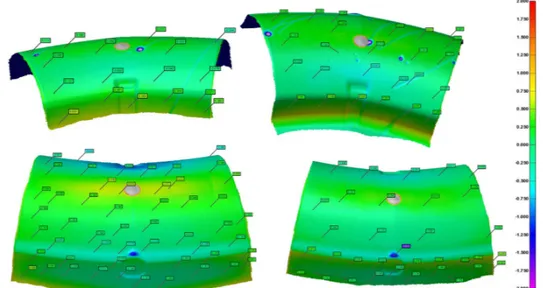
3D dimensional controls have been performed after cold frame trimming on all the four formed sheets, results shown a good repeatability with dimensional checks within the targeted tolerances of +/-0,5mm. Results obtained are equivalent to those obtained by conventional SPF.
Figure 17: 3D dimensional check results: gap in mm between theoretical CAD part and scanned parts on the four formed sheets – highest gap values are on the areas of thermocouples heads and wires on the 2 first sheets and events holes locations.
Microstructure checks with alpha case layer determination have not yet been performed on the four formed sheets, nevertheless, form experience on previous IR forming, Aurock has a high level of confidence on the results due to the fact that thermal measurements with thermocouples indicated no overheating on the blank nor on the metallic die. Previous analyses performed by ICA shown acceptable microstructure after IR forming, equivalent to conventional SPF. No major increase of the grain size was observed and a very low alpha case layer was detected. Infra-red SPF does not affect the material:
10
Figure 18: Microstructure and α-case observations on an IR formed sheet
4-Conclusions and outlooks
Aurock developed direct heating by Infrared emitters and succeed in forming 4 series 1.5x1m² Ti6Al-4V blanks with a total control of the forming parameters. A homogeneous temperature of the blank all along the forming cycle is obtained thanks to lamp power modulations during the cycle set by numerical techniques. This methods developed by Aurock enables to secure the thermal regulation of the blank with a full control of the radiative flux needed at different stage of the forming. Results obtained on the formed parts were stable and repeatable regarding to complete forming and dimensional criterion as well as post-forming thickness distribution. Furthermore, microstructure is not affected by the quick and direct heating. Numerical thermo-mechanical predictions are in very good agreement to the experimental results and enable robust machine setup for series Infrared SPF parts production. Simulation tools and material characterizations are available and validated for the future to reduce the experimental loops and to adapt potential definition variations of other parts design.
5-Acknowledgements
The authors acknowledge the Region Occitanie for its financial support to achieve this project thanks to the Easynov call and FEDER funds. The authors acknowledge also Neotim for its contribution for in-situ thermal fluxes measurements, CRITT Mécanique et Composites for the water jet cut of the formed sheets and CML for the three dimensional checks.
6-References
[1] G.Giuliano, Superplastic forming of advanced metallic materials – methods and applications, ISBN 978-1-84569-753-2 (2011), p.12. [2] F.Nazaret, Method of controlling a superplastic forming machine and correspondent machine, FR patent number FR3034690A1, 2015 – WO 2016/162642 A1, 2016.
[3] A.Jocelyn, A.Kar, A.Fanourakis, T.Flower, M.Ackerman, A.Keevil, J.Way. Indirect versus direct heating of sheet materials: superplastic forming and diffusion bonding using lasers, Journal of Materials Engineering and Performance, Volume 19(4), pp 527-532, June 2010. [4] P.Wilson, C.Couzins-Short, H.Chesterton, A.Jocelyn, Superplastic Forming and Diffusion Bonding: Current Cost, Value and Future Trends, Key Engineering Materials Vol 433, pp 119-124, 2010.
[5] D.Mauduit, M.LeFournier, K.Grondin, T.Pottier, Y.Le-Maoult, Industrial applications of the superplastic forming by using Infrared heaters, International Conference on the Technology of Plasticity, ICTP 2017, Cambridge, UK.
[6] F.Nazaret, O.Barrau, G.Bernhart, T.Cutard, Innovative SPF toolings based on reinforced refractory concretes, ICSAM2009 – International Conference on Superplasticity in Advanced Materials (Seattle) Invited lecture 2009.