HAL Id: hal-00862293
https://hal-iogs.archives-ouvertes.fr/hal-00862293
Submitted on 16 Sep 2013
HAL is a multi-disciplinary open access
archive for the deposit and dissemination of
sci-entific research documents, whether they are
pub-lished or not. The documents may come from
teaching and research institutions in France or
abroad, or from public or private research centers.
L’archive ouverte pluridisciplinaire HAL, est
destinée au dépôt et à la diffusion de documents
scientifiques de niveau recherche, publiés ou non,
émanant des établissements d’enseignement et de
recherche français ou étrangers, des laboratoires
publics ou privés.
Efficient Bragg-like operation of intracavity
low-efficiency plane gratings
Aurélie Moreau, Isabelle Zaquine, Alain Maruani, Robert Frey
To cite this version:
Aurélie Moreau, Isabelle Zaquine, Alain Maruani, Robert Frey. Efficient Bragg-like operation of
intracavity low-efficiency plane gratings. Journal of the Optical Society of America B, Optical Society
of America, 2005, 22 (11), pp.2289. �hal-00862293�
Efficient Bragg-like operation of intracavity
low-efficiency plane gratings
Aurélie Moreau, Isabelle Zaquine, and Alain Maruani
Département Traitement du Signal et de l’Image, Ecole Nationale Supérieure des Télécommunications, 46, rue Barrault, 75634 Paris Cedex 13, France
Robert Frey
Département Traitement du Signal et de l’Image, Ecole Nationale Supérieure des Télécommunications, 46, rue Barrault, 75634 PARIS cedex 13, France and Laboratoire Charles Fabry de l’Institut d’Optique, Centre Scientifique de
Paris Sud Bât 503, 91403 Orsay Cedex, France
Received February 18, 2005; revised manuscript received May 19, 2005; accepted May 23, 2005 The diffraction regime of a thin grating inserted in a Fabry–Perot cavity is investigated. Our calculations show that, at Bragg incidence, a single diffraction order can be selectively enhanced, giving rise to a very efficient Bragg-like diffraction regime. The optimization of the device is studied as a function of the resonator thickness and finesse and the grating position inside the Fabry–Perot cavity. The angular and wavelength selectivities are also investigated. The device could be easily integrated and would be very useful for optical signal-processing applications. © 2005 Optical Society of America
OCIS codes: 050.1970, 050.1950, 050.2230.
1. INTRODUCTION
Diffraction efficiency increase is a very important issue in optical signal processing.1–3 The Bragg diffraction regime,4 in which the entire diffracted energy is concen-trated in a single diffraction order, is the most efficient re-gime. This regime can be achieved, at Bragg incidence, only beyond some grating thickness threshold. It has been shown that inserting a volume grating in a Fabry–Perot resonator is a good means of improving its efficiency, es-pecially if the volume grating fills the cavity entirely.5In that case, the thickness threshold toward the Bragg re-gime can be significantly lowered6because of the multiple paths in the nonlinear medium, but many efficient non-linear media are available only in such small thicknesses that no Bragg regime can be obtained in this way.
Here, we investigate another diffraction regime occur-ring when a thin grating is inserted in a Fabry–Perot resonator. Most of the time, such a device is operated at normal incidence to avoid the walk-off of the read beam in the Fabry–Perot cavity.7–13 In that case, only the read beam is Fabry–Perot resonant, and the diffracted beams are all enhanced in the same manner. To favor a unique diffraction mode, we use Bragg incidence and tune the resonator accordingly. Both read and first-order diffracted beams are then Fabry–Perot resonant, whereas higher-order diffraction modes are not. This results in a selective enhancement that can lead, as we will show, to a diffrac-tion regime in which the intensity of higher diffracdiffrac-tion or-ders is at least 100 times smaller than that of the main diffraction order. This can usually be obtained only with volume gratings or Bragg gratings, and we call it a “Bragg-like” diffraction regime.
Section 2 describes the model used for the calculations. Section 3 shows how the cavity thickness, the reflection
coefficient, the one-pass grating efficiency, and the posi-tion of the grating in the cavity can be chosen in order to obtain a Bragg-like diffraction regime and to optimize the diffraction efficiency. Finally, Section 4 deals with the an-gular and wavelength selectivities of the device.
2. MODEL
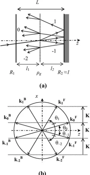
The unslanted sinusoidal refractive-index grating, of in-tensity diffraction efficiency g, is inserted between two
mirrors with reflection coefficients R1and R2⬇1,
respec-tively [see Fig. 1(a)]. The thickness of this asymmetric Fabry–Perot cavity is L. The real refractive index of the cavity medium is n. When illuminated by a plane wave of wavelength0 and incidence angle 0, the grating gives
rise to a transmitted beam (order 0) and two diffraction orders −1 and +1.
The propagation angle p=共z,kp
F,B兲 of the pth order
forward- and backward-diffracted waves (of wave vectors kpFand kpB, respectively) in the intracavity medium is de-termined by the Raman–Nath relation: k共sinp− sin0兲
= pK, where k = 2 n/0and K = 2/⌳ (⌳ is the spatial
pe-riod of the grating). The corresponding forward and back-ward wave vectors kp
F,B
are shown in Fig. 1(b).
When the read beam is set at Bragg incidence B共0
=B兲, the diffraction order −1 is symmetrical to the read
beam with respect to the z axis [see Fig. 1(b)]. The Fabry– Perot cavity can then be tuned to both read and diffraction-order −1 beams. Considering that order +1 is generally not Fabry–Perot resonant in the device, for the sake of simplicity, the waves of order p greater than one are neglected and only the higher order −2, resulting from
the diffraction of the resonant order −1 and symmetrical to the order +1 with respect to the z axis, is taken into account.
The reflected diffracted amplitudes of orders 0, −1, +1, and −2 are calculated using the product of matrices de-scribing reflection on the mirrors, propagation in the cav-ity, and diffraction on the thin grating, using a standard technique used for the description of multilayered dielec-tric media.14
A four-dimensional vector F (or B) is formed with the four forward- (or backward-) propagating complex ampli-tudes Spcorresponding to the diffraction orders from p =
−2 to p = + 1. F共resp B兲 =
冢
S−2 S−1 S0 S+1冣
F共resp B兲 . 共1兲An eight-dimensional vector col共F,B兲 is formed with all amplitudes. Beam amplitudes considered before and after the device are labeled using subscripts bd and ad, respec-tively.
Considering the device of Fig. 1(a), the beam ampli-tudes before and after the device are related by
冉
Fbd Bbd冊
= M1P1DP2M2冉
Fad Bad冊
, 共2兲where M1and M2describe the reflection on the front and
back mirrors, respectively; P1and P2are the propagation
between the front mirror and the grating and that be-tween the grating and the back mirror, respectively; and
D is the diffraction of the plane grating inserted in the
cavity. M1, M2, P1, P2, and D are all 8⫻8 matrices
de-scribed hereafter as:
Mi= 1 ti
冉
I4 − riI4 − riI4 I4冊
for i =共1,2兲, 共3兲where I4 is the four-dimensional identity matrix; and ri
and ti are, respectively, the amplitude reflection and
transmission coefficients of the considered cavity mirror.
riis related to Riby兩ri兩2= Ri.
The propagation matrices are diagonal; each diagonal term represents the phase change共kpF,B· z l兲 for a beam of wave vector kp
F,B
propagating on a distance l. The two cases considered here are the propagation between the front mirror and the grating共l1兲 and the propagation
be-tween the grating and the back mirror共l2兲. The resonator
length L is the sum of l1and l2:
Pi=
冉
Pi4* 04 04 Pi4
冊
for i =共1,2兲, 共4兲 where 04 is the four-dimensional zero matrix and Pi4 is
the propagation submatrix:
Pi4=
冢
exp共jk−2· z li兲 0 0 0 0 exp共jk−1· z li兲 0 0 0 0 exp共jk0· z li兲 0 0 0 0 exp共jk+1· z li兲冣
.Fig. 1. (a) Setup of the thin grating inside the Fabry–Perot reso-nator and (b) the wave vectors of all considered diffraction or-ders.
The matrix D is built from the symmetric, tridiagonal diffraction submatrix D4: D =
冉
D4 −1 0 4 04 D4冊
, with D4=冢
tg dg 0 0 dg tg dg 0 0 dg tg dg 0 0 dg tg冣
. 共5兲The D4matrix relates the amplitudes before the grating
to the amplitudes after the grating. The amplitude of or-der p after the grating is the sum of three contributions: The first one is due to the transmission by the grating of the amplitude of the order p, and the others are due to the diffraction by the grating of the amplitudes of the orders
p + 1 and p − 1. The amplitude transmission coefficient tg
and the diffraction coefficient dg= jg
1/2of this sinusoidal
grating are related by the equation兩tg兩2+ 2兩dg兩2= 1, where
gis the intensity diffraction efficiency of the grating. As
not all the diffracted beams are considered in our analysis (we have limited our investigation to four diffraction-order beams only), the diffraction matrix is not unitary.
The numerical calculations are performed using a simpleMATLABroutine.
3. DEVICE OPTIMIZATION
This section is devoted to the optimization of the device in terms of diffraction efficiency and Bragg-like operation. We define the diffraction efficiency as the ratio of the re-flected diffracted intensity to the input intensity of the read beam, and we use the notationDwhen we consider
the order −1 beam. The refractive index of the medium is
n = 2.8, and the wavelength0 is set at 1m. The Bragg
angle is related to the grating period by sin共B兲
=0/共2n⌳兲. The incidence is set at the Bragg angle (B
= 5° for the 2m grating period ⌳ considered here as an example). Finally, the back mirror is almost totally reflec-tive共R2⬇1兲.
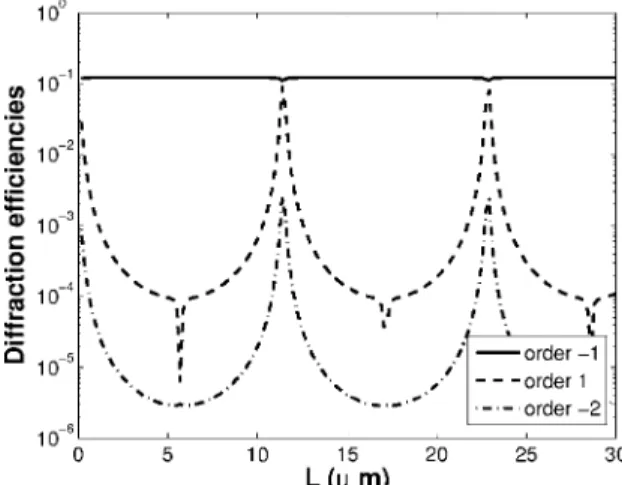
Figure 2 shows the variation of the diffracted intensi-ties as a function of the resonator length, where order 0 and order −1 are kept Fabry–Perot resonant (we consider only the resonator lengths for which order 0 and −1 are resonant). The thin grating of diffraction efficiency g
= 10−4is positioned in the middle of the resonator, and the
front-mirror reflectivity is R1= 0.8.
As orders 0 and −1 are always Fabry–Perot resonant, the diffraction efficiency is constantly equal toD= 10−1,
showing a very large enhancement (by a factor of 1000) as compared with that of the bare grating. The diffraction ef-ficiencies of orders +1 and −2 are lower than that of order −1 by more than 20 dB, except for cavity lengths corre-sponding to quasi-resonance of these orders (i.e., when or-ders +1 and −2 are also close to another Fabry–Perot resonance) in the cavity. The closer that the +1 and −2 or-ders are to the Fabry–Perot resonance, the greater their diffraction efficiencies are. When the cavity is tuned to all considered diffraction orders, the diffraction efficiency of order +1 is almost as large as that of order −1 so that the diffraction efficiency of order −1 slightly decreases owing to the read-beam depletion by the order +1 beam. As
shown in Fig. 2, this unfavorable situation can be easily avoided if the proper the resonator length is chosen. It must also be stressed that what we have called the Bragg-like operation of plane gratings is possible with very thin devices that could be processed using nanotechnologies. However, for micrometer devices, the thickness of the grating must be taken into account, and the results psented here are no longer valid. Finally, although this re-sult has almost no practical consequences, let us note that the decrease of orders +1 and −2 is an antiresonance ow-ing to the sign change of the transmitted order 0 phase.
Figure 3 shows the influence of the reflection coefficient
R1 on the diffracted intensities for a cavity thickness L
= 3.55m, with the thin grating of diffraction efficiency g= 10−4again set in the middle of the resonator. In Fig.
3(a), the diffraction efficiency of order −1 exhibits a maxi-mum at R1= 0.96, which means that almost all the
read-beam energy is transferred to the main diffraction order. This demonstrates the very high (10 000 in this case, for instance) increase in diffraction efficiency of the device. Naturally, the front-mirror reflectivity corresponding to the maximum diffraction efficiency increases when g is
decreased. Beyond this optimal value, the diffraction effi-ciency steeply decreases, owing to the fact that the energy
Fig. 2. Logarithmic plot of diffraction efficiencies as a function of resonator length withg= 10−4and R1= 0.8.
Fig. 3. (a) Diffraction efficiency of order −1 and (b) Bragg ratios as a function of the reflection coefficient of the first mirror, with
is diffracted back into order 0. The Bragg ratios shown in Fig. 3(b) represent the intensity ratio of the higher dif-fraction orders +1 and −2 to the Fabry–Perot resonant −1 diffraction order. For R1⬎0.51 the Bragg ratio of order +1
is less than −20 dB, showing again that the actual Bragg-like regime is easily obtained by inserting the plane grat-ing in the Fabry–Perot cavity. Moreover, a very steep de-crease of the Bragg ratio of this order with increasing Fabry–Perot finesse can be seen, owing to the good dif-fraction efficiency of order −1. This decrease continues be-yond R1= 0.96 because of the phase change of the laser
re-flected beam. Finally, the Bragg ratio of order −2 keeps almost constant at a very low value共⬇−45 dB兲, as the in-tensity of this mode is proportional to that of order −1.
Figure 4 shows the variation of diffracted intensities as a function of the one-pass efficiency of the grating. The thin grating of diffraction efficiencygis set in the middle
of the 3.55m long resonator, and the front-mirror reflec-tivity is R1= 0.8. The diffraction efficiency of the order −1
beam, shown in Fig. 4(a), exhibits a maximum at g
= 3.10−3, where all the read-beam energy is transferred to
the main diffraction order as occurs when the resonator finesse is optimized [see Fig. 3(a)]. The Bragg ratios are
represented in Fig. 4(b). The Bragg ratio of order +1 keeps almost constant on this logarithmic scale, owing to the fact that the energy of the 0 order beam is transferred in the same way to the order −1 beam and to the order +1 beam by the grating so that only the Fabry–Perot reso-nance makes the difference. The Bragg ratio of order −2 scales likeg, because the order −2 originates only from
the diffraction of order −1. For the chosen values of R1
and R2, Bragg ratios are well below −20 dB, which means
that a Bragg-like diffraction regime is easily obtained, whatever the one-pass efficiency of the thin grating.
Results shown in Figs. 2–4 correspond to a plane dif-fraction grating set in the middle of the cavity. Figure 5 shows the dependence of diffracted intensities as a func-tion of the posifunc-tion of the grating in the cavity for a cavity thickness L = 3.55m, a reflection coefficient R1= 0.8, and
a one-pass diffraction efficiencyg= 10−4. As expected, the
intensity of order −1 beam is constant. The sharp mini-mum of the higher orders is due to an antiresonance of these orders, owing to a phase discontinuity. The results shown in Fig. 5 demonstrate that at Bragg incidence, the position of the grating has almost no influence on the dif-fraction efficiency of order −1 or on the difdif-fraction regime. This will simplify the fabrication of such devices. Let us mention only that, if necessary, the choice of the position of the grating could allow a much higher Bragg selectivity for the device. It must also be stressed that, owing to the low cavity thickness, the results presented here are valid only for very thin gratings (smaller than 100 nm, ob-tained using quantum wells, for instance). However, the same results are obtained for thicker gratings, provided the cavity thickness is increased.
4. SELECTIVITY
In this section, we investigate angular and wavelength selectivities, which are important parameters for the ap-plication of any diffraction device. The thin grating (2m grating period) of diffraction efficiencyg= 10−4is set in
the middle of the 3.55m long resonator. The front-mirror reflectivity is R1= 0.8 and the back mirror is
al-most totally reflective.
Fig. 4. (a) Order −1 diffraction efficiency and (b) Bragg ratios as a function of the one-pass efficiency of the grating with L = 3.55m and R1= 0.8.
Fig. 5. Logarithmic plot of diffraction efficiencies as a function of the position of the grating inside the cavity withg= 10−4, L
= 3.55m, and R1= 0.8.
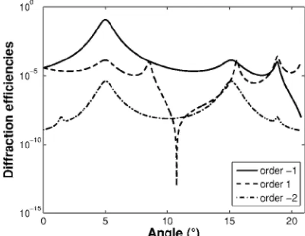
Fig. 6. Logarithmic plot of diffraction efficiencies as a function of incidence angle (inside the cavity) withg= 10−4, L = 3.55m,
The angular selectivity of the device was evaluated by calculating the diffracted intensities of orders −1, +1, and −2 as a function of the incidence angle of a laser beam of wavelength 0= 1m inside the cavity (see Fig. 6). The
incidence angle of the laser beam outside the cavity is varied from 0 to/2. Maxima correspond to resonances of the different beams. The Fabry–Perot is tuned to both read and diffraction order −1 beams only for0= 5° (Bragg
incidence for the 2m grating period chosen here). As a consequence, the diffraction efficiency of the Bragg order −1 is maximum for this angle and decreases on both sides. The 3 dB width is 0.76°, which means that applica-tion to optical processing of complex signals such as cor-relation could be performed using such devices. Moreover, there is a 30 dB ratio between the order −1 beam and the higher orders at 0= 5°. The maximum diffraction
effi-ciency of order −1 beam exceeds that of higher diffraction orders at any angle by 20 or 30 dB, which again demon-strates the Bragg-like regime of the device.
The wavelength selectivity of the device was evaluated by calculating the diffracted intensities as a function of the wavelength of the read beam for0= 5° (see Fig. 7).
When the read wavelength fulfills the Fabry–Perot reso-nance condition, the diffraction order −1 is also resonant, hence exhibiting periodic maxima of its intensity. In Fig. 7(a) where the diffraction efficiency of order −1 is plotted on a linear scale, we can see a variation of the amplitude of the peaks due to the fact that the incidence angle is set at Bragg only for 0= 1m. In Fig. 7(b) a logarithmic
scale has been chosen so that higher orders can be com-pared with the main diffraction order. Maxima of the higher-diffraction-order intensities are obtained on the one hand when the cavity is tuned to the read beam and on the other hand when it is tuned to the diffraction order +1 beam. The diffraction order −2 and +1 beams fulfill the same resonance condition because they have opposite angles. Because resonances for orders −1 and +1 never oc-cur at the same wavelength, there is a 30 dB ratio be-tween maxima of diffraction order −1 intensity and maxima of the higher-diffraction-order intensities. Multi-wavelength efficient operation of the device is possible in
the Bragg regime, which indicates that wavelength-multiplexed Bragg-like plane gratings could also be used with this device.
5. CONCLUSION
Our calculations show that a Bragg-like diffraction re-gime can be obtained with a thin intracavity diffraction grating; the wavelength, incidence angle, and length must be chosen such that order 0 is simultaneously Fabry–Perot resonant and at Bragg incidence, so that dif-fraction order −1 is symmetrical to order 0 and is also Fabry–Perot resonant. We can notice that Bragg-like op-eration of plane gratings can be performed with microme-ter cavities if the cavity length is not tuned to quasi-resonance of higher orders. For a giveng, the reflection
coefficient of the front mirror can be chosen in order to maximize the diffraction efficiency of the device, and Bragg-like operation can be achieved, even with small dif-fraction efficiency of the grating. The grating position has no influence on the device performance, which makes the device easy to fabricate. Good angular selectivity has been demonstrated that could be useful for information pro-cessing. Multiwavelength efficient operation is possible as long as Fabry–Perot resonances are taken into account for the choice of the wavelengths. This device is a very promising one, as it combines very good performance and ease of integration using the state of the art photonics nanotechnologies.
A. Moreau’s e-mail address is Aurelie.Moreau@enst.fr.
REFERENCES
1. L. Hesselink, S. S. Orlov, and M. C. Bashaw, “Holographic data storage systems,” Proc. IEEE 92, 1231–1280 (2004). 2. J. Zhao, X. Shen, and Y. Xia, “Beam splitting, combining
and cross coupling through multiple superimposed volume index gratings,” Opt. Laser Technol. 33, 23–28 (2001). 3. Y. Ding, D. D. Nolte, M. R. Melloch, and A. M. Weiner,
“Time domain image processing using dynamic holography,” IEEE J. Sel. Top. Quantum Electron. 4, 332–340 (1998).
4. M. G. Moharam, T. K. Gaylord, and R. Magnusson, “Criteria for Bragg regime diffraction by phase gratings,” Opt. Commun. 32, 14–18 (1980).
5. L. Menez, I. Zaquine, A. Maruani, and R. Frey, “Intracavity Bragg grating,” J. Opt. Soc. Am. B 16, 1849–1855 (1999). 6. L. Menez, I. Zaquine, A. Maruani, and R. Frey, “Bragg
thickness criterion for intracavity diffraction grating,” J. Opt. Soc. Am. B 19, 965–972 (2002).
7. D. D. Nolte, K. M. Kwolek, C. Lenox, and B. Streetman, “Dynamic holography in a broad-area optically pumped vertical GaAs microcavity,” J. Opt. Soc. Am. B 18, 257–263 (2001).
8. A. Sinha and G. Barbastathis, “Resonant holography,” Opt. Lett. 27, 385–387 (2002).
9. L. Escoubas, F. Flory, F. Lemarchand, A. During, and L. Roux, “Enhanced diffraction efficiency of gratings in multilayers,” Opt. Lett. 25, 194–196 (2000).
10. C. De Matos, H. L’Haridon, A. Le Corre, R. Lever, J. C. Kéromnès, G. Ropars, C. Vaudry, B. Lambert, and M. Pugnet, “Epitaxial liftoff microcavities for 1.55m Fig. 7. (a) Order −1 diffraction efficiency and (b) Diffraction
ef-ficiencies plotted as a function of wavelength withg= 10−4, L
quantum-well spatial light modulators,” IEEE Photonics Technol. Lett. 11, 57–59 (1999).
11. R. Grac, M. Pugnet, J. H. Collet, B. Lambert, C. De Matos, H. L’Haridon, A. Le Corre, and J. O. White, “Photodiffraction in InGaAs/InGaAsP multiple quantum wells enclosed in a microcavity,” Superlattices Microstruct.
22, 505–509 (1997).
12. K. Tian and G. Barbastathis, “Cross talk in resonant
holographic memories,” J. Opt. Soc. Am. A 21, 751–756 (2004).
13. D. D. Nolte and K. M. Kwolek, “Diffraction from a short-cavity Fabry–Pérot: application to photorefractive quantum wells,” Opt. Commun. 115, 606–616 (1995)
14. M. Born and E. Wolf, Principle of Optics (Pergamon, 1970), p. 55.