HAL Id: hal-01511560
https://hal.archives-ouvertes.fr/hal-01511560
Submitted on 21 Apr 2017
HAL is a multi-disciplinary open access
archive for the deposit and dissemination of
sci-entific research documents, whether they are
pub-lished or not. The documents may come from
teaching and research institutions in France or
abroad, or from public or private research centers.
L’archive ouverte pluridisciplinaire HAL, est
destinée au dépôt et à la diffusion de documents
scientifiques de niveau recherche, publiés ou non,
émanant des établissements d’enseignement et de
recherche français ou étrangers, des laboratoires
publics ou privés.
Receive Antenna Shift Keying Modulation Testbed for
Wireless Communications Systems
Yvan Kokar, Jean-Christophe Prévotet, Maryline Hélard
To cite this version:
Yvan Kokar, Jean-Christophe Prévotet, Maryline Hélard. Receive Antenna Shift Keying Modulation
Testbed for Wireless Communications Systems. 2016 IEEE Globecom Workshops (GC Wkshps),
Dec 2016, WASHINGTON DC, United States. pp.1 - 6, �10.1109/GLOCOMW.2016.7849016�.
�hal-01511560�
Receive Antenna Shift Keying Modulation Testbed for Wireless
Communications Systems
Yvan Kokar, Jean-Christophe Pr´evotet, Maryline H´elard
IETR, INSA de Rennes, France
Abstract—Time Reversal (TR) applied to wireless communi-cations systems has already shown very promising results at low Signal-to-Noise Ratio (SNR). In this paper, we describe a prototype implementing the Receive Antenna Shift Keying (RASK) modulation scheme combined with TR. RASK mod-ulation consists in focusing a signal onto one receive antenna among several antennas. The index of the target receive antenna is updated every symbol duration and is coded by the binary sequence to be transmitted during the considered symbol. For spatial signal focusing, TR pre-filtering technique is used at the transmitter side. In this study, we also propose a very simple and efficient way to discriminate the collected information at the receiver side. This technique allows receivers with low complexity to be implemented in a multiple-input multiple-output (MIMO) configuration. Moreover, we evaluate the performance of RASK modulation according to the number of antennas at the transmitter and receiver side and demonstrate the feasibility of our approach in a realistic scenario.
I. INTRODUCTION
Among the different techniques that have been used to improve the Energy Efficiency of fifth generation (5G) cellular networks, one technique consists in using spatial modulation (SM)[1]. This technique has already provided significant per-formances and consists in improving spectral efficiency by using an additional spatial dimension. In the SM schema, two distinct systems exist, known as open and close loop SM.
In the open loop SM, a data block of Nt symbols is
coded at the transmitter side, where Nt is the number of
transmitting antennas. The receiver exploits the difference in the received signals to retrieve the index of the transmitting antenna and hence the modulated information [2]. If the capacity of conventional MIMO systems is known to linearly increase with the number of antennas, it is also established that they are not very energy efficient, especially due to the energy consumption of different radio frequency (RF) chains [3]. By activating only one or a part of the transmit antennas as proposed in [4], SM applied at the transmitter side allows for reducing the complexity, synchronization issues as well as energy consumption leading to a more energy efficient system. Since all transmit antennas are not simultaneously activated, only a limited number of RF front-ends will consume energy. A first implementation of open SM has been presented in [5]. In the close loop modulation scheme, the information is carried by the index of the antenna that receives a signal [6], [7]. Note that for RASK modulation, the sent signal does not carry any useful information. Accordingly, a very simple de-modulation, based on maximizing the real part of the received
The authors would like to thank the SPATIAL MODULATION project funded by the French National Research Agency (ANR) and Orange Labs.
signal [6], is performed at the receiver side which makes this technique very promising for future wireless devices. Moreover, RASK modulation can be used simultaneously with another classical modulation (single carrier or multi-carrier) in order to increase the spectral efficiency [5]. In order to imple-ment this scheme, precoding techniques have to be considered, based on the knowledge of the channel. These techniques have to be implemented at the transmitter side to enable an efficient focusing on the targeted antenna. One promising precoding technique is TR that enables to focus a signal in both time and space, very efficiently. TR has been introduced for underwater communications [8] and more recently in the wireless communications domain [9]. In the MIMO context, the spatial focusing property of TR has already been exploited and demonstrated its robustness and performance for multi-users and multi-streams communications [10].
The purpose of this paper is to describe a first prototype implementing the RASK close loop SM on a real channel and demonstrate the feasibility of the approach by providing measurements results in a realistic scenario. The prototype is based on an existing platform already available in our lab that implements TR OFDM transceivers. We took benefit from this existing platform (calibration, TR in the frequency domain, etc.) in order to obtain results in the RASK scheme. Note that OFDM is only used here as an already available signal support and is not the purpose of the current study. Note that, independently of OFDM, a major interest of this approach is that it enables the implementation of very simple receivers since it does not require any complex synchronization or demodulation. Only power levels are estimated to retrieve the transmitted information.
The paper is organized as follows: Section II describes the prototype which has been implemented. The system model is presented in section III and provides information related to the RASK modulation/demodulation scheme. Performance results are presented in section IV. Finally, conclusions are given in section V.
II. TESTBED DESCRIPTION
The proposed prototype can be separated into software and hardware parts. The hardware part is composed of the Tx board at the transmitter side, the Rx board at the receiver side and an Ethernet switch to communicate with external devices. The software parts consist in processing Tx and Rx baseband (BB) algorithms offline, on an external workstation using Matlab. These parts will be detailed in section III.
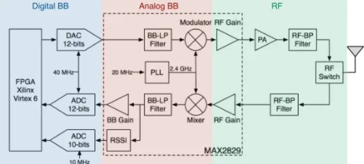
DAC 12-bits BB-LP Filter PA ADC 12-bits BB-LP Filter RF-BP Filter RF Switch 40 MHz 20 MHz PLL 2.4 GHz BB Gain ADC 10-bits RSSI Mixer RF Gain RF-BP Filter Modulator RF Gain 10 MHz MAX2829 FPGA Xilinx Virtex 6 Digital BB Analog BB RF
Fig. 1: RF interface description
Both Tx and Rx boards are part of the Rice university’s WARP Platform [11]. These boards share the same structure and can transmit and receive data on different time slots, al-lowing therefore time division duplex (TDD) mode to be used. Each board is composed of one FPGA-based motherboard (WARP v3), one additional radio board (FMC-RF-2X45) and one clock board (CM-MMCX). A motherboard contains one Xilinx Virtex 6 FPGA and two RF interfaces. The radio board features also two RF interfaces, providing up to four antennas per board.
A. FPGA Design
The two FPGAs are both configured with the WARPLab Reference Design. In this design, FPGAs are only used as data buffers to store digital data samples coming from /to the workstation. Several interfaces are also implemented to configure and communicate with the RF interfaces directly from MATLAB. Due to memory limitation of the boards, a
maximum number of 56.220samples per frame may be stored
in both Tx and Rx boards which leads to a maximum frame duration of 1.46 s.
B. RF Interface Description
The RF interface is described in Fig. 1. This interface is based on the MAX2829 RF transceiver used to translate signals between BB and RF parts at 2.4 GHz. A couple of 12 bits digital-to-analog converters (DAC) and 12 bits analog-to-digital converters (ADC) constitute the interface between the digital and analog circuits for both I and Q channels. The MAX2829 also features, on the Rx path, a dedicated received signal strength indicator (RSSI) which allows to quantify the received power. This RSSI is connected to an ADC coded into 10 bits and thus is capable of determining 1024 levels of power. Furthermore, since the RSSI ADC clock is set to 10 MHz and I/Q symbols are generated according to a 40 MHz clock, the received power may be estimated every four I/Q samples. Each RF interface is connected to an omni-directional antenna with a 6 dBi gain which is connected to an RF switch in order to consider both Tx and Rx paths.
C. Various Clock Synchronization
In order to alleviate the synchronization issue that is not the main subject of this work, both Tx and Rx boards are
wired with dedicated cables connected to the clock boards. Two types of synchronizations are considered : the sampling clock and RF clock synchronizations. A 40 MHz sampling clock is provided from Tx board to Rx board in order to avoid sampling frequency offset (SFO). This offset is respon-sible for an increased time offset which leads to inter-carrier interference (ICI) due to a mismatch in carrier spacing. A 20 MHz reference clock, used for carrier frequency generation, is also forwarded from Tx board to Rx board to avoid the carrier frequency offset (CFO) that causes loss of orthogonality between subcarriers and therefore ICI.
III. SYSTEM DESCRIPTION
This section provides an overall description of the im-plemented system. A TDD MIMO transmission between a
transmitter featuring Nt antennas and a receiver with Nr
antennas is considered. In this communication, two types of modulations are simultaneously used : a classical OFDM mod-ulation which is used as a carrying waveform and the RASK
modulation which allows to transmit log2(Nr) additional bits
per OFDM symbol.
For the RASK modulation, during the mthOFDM symbol
period, the transmitter focuses the complete OFDM symbol
onto receive antenna Rxn with 1 ≤ n ≤ Nr, by using TR
pre-filtering. The index n of the receive antenna is determined
according to the value of the log2(Nr) bits to transmit during
the mth OFDM symbol period. For instance, if the binary
sequence b = [1001] with Nr = 4 has to be transmitted, the
first sent symbol will focus on the antenna whose index is coded by the first two bits (10) of b, i.e., the antenna index n =
2
P
k=1
bk2k−1+ 1 = 3. Similarly, the second symbol will
focus on the antenna whose index (2) is coded by the last two bits (01).
As already mentioned, signal focusing is achieved by TR. Applying TR in frequency domain, which is the case in our testbed, consists in multiplying the modulated symbols by a precoding matrix P . This precoding matrix is equal to the transpose conjugate of the propagation channel [12]. Hence, in order to apply the TR technique, the channel state information (CSI) is required at the transmitter side. In theoretical TDD systems, physical uplink (UL) and downlink (DL) channels are reciprocal since they operate on the same carrier frequency [13]. Therefore, prior to any data transmission, an UL trans-mission (from Rx board to Tx Board) is performed in order to obtain the CSI at the transmitter side.
However, in practice the communication channel does not only consist of the physical channel, but also takes into account the transmitter and receiver hardware paths which can introduce an unknown amplitude scaling and phase shift between the UL and DL channels. In order to compensate these impairments, an internal calibration between Tx board antennas is performed at every switch on of the platform. This calibration procedure is out of scope of this paper.
PN Sequence Generator OFDM Modulator BPSK Modulator Frame detection LS Estimator OFDM Demodulator Average Frame detection LS Estimator OFDM Demodulator Average Frame detection LS Estimator OFDM Demodulator Average matrix (np(NFFT+LCP) x NT) from Tx Board vector (np(NFFT+LCP) x 1) to Rx Board Ĥ1j 1 ≤ j ≤ NT Baseband Rx Baseband Tx
Fig. 2: Uplink Baseband processing
In the following sections, the required BB processing that aims to implement the combination of OFDM and RASK modulation will be detailed.
A. UL transmission : Channel estimation
During the UL transmission, the transmitter has to estimate the UL propagation channel H which can be modeled as a
complex Nr× Nt matrix for each sub-carrier. Let denote bH
the estimate of H. Note that, for dynamic channels, bH is valid
only on a time duration shorter than the coherence time Tc of
the channel. Therefore the total frame duration (UL and DL
frame) must occur within a duration smaller than Tc.
For UL transmission, BB Rx has to generate a pilot frame
which will be used by BB Tx to evaluate bH as illustrated in
Fig. 2.
1) BB Rx processing: The channel estimation is performed
in frequency domain, therefore the pilot symbol is also built in this domain. The pilot symbol generation follows several steps. First, a pseudo-noise (PN) sequence is generated and passed through a binary phase shift keying (BPSK) modulator to build frequency symbols. These symbols are then applied to an OFDM modulator to generate the pilot symbol in time
domain. Note that, in order to evaluate bH for all sub-carriers
of the OFDM spectrum, the PN sequence length is equal to
the IFFT size (NF F T).
In order to evaluate bH, we have applied the method
proposed in [14]. This method consists in sending np pilot
symbols per pilot frame and in calculating the average of the
np least square (LS) estimates. Using this technique, authors
have shown that the estimation noise decreases proportionally
to np. In our work, we have chosen np= 5.
In order to evaluate the full matrix bH, each antenna of
the Rx board successively sends the generated pilot frame.
Therefore, the UL frame is composed of Nr pilot frame, and
5.Nr pilot symbols.
2) BB Tx processing: UL channel estimation is performed
simultaneously at each Tx board’s antenna and successively for each Rx board’s antenna. As previously mentioned, the LS estimation technique, which consists in dividing the re-ceived symbol by the pilot symbol, is used. This operation is performed for each sub-carrier.
As soon as a pilot frame from the first Rx board’s antenna
(Rx1) is received, the OFDM demodulation is applied in
parallel on the Ntantennas of the Tx board. An LS estimation
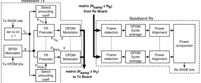
matrix (Nsamp x NT) to Tx Board Select precoding coeff TR Precoder OFDM Modulator X In BPSK Modulator bin to int + 1 Select precoding coeff OFDM Modulator Tx RASK bits Tx OFDM bits TR Precoder Frame detection Frame detection OFDM Symb average OFDM Symb average Power Alignment Power Alignment Power comparator Rx RASK bits P1In PNTIn matrix (Nsamp x NR) from Rx Board Baseband Tx Baseband Rx P1In . X PNTIn . X
Fig. 3: Downlink Baseband processing
is then performed before averaging the 5 LS estimates to
obtain bH1j for j = 1, . . . , Nt.
By applying the same estimation on the next Nr−1 received
pilot frames, the full bH matrix is obtained and will be used
to compute the precoding matrix P (P = bHH where bHH is
the transpose conjugate of bH).
B. DL transmission : Data transmission
The architecture of the DL BB processing is given in Fig. 3. It is composed of both BB Tx and Rx.
1) BB Tx processing: For each OFDM symbol, the bit
stream to transmit is divided into two sets containing log2(Nr)
bits and NF F T bits respectively. The first set of log2(Nr) bits
constitutes the RASK bits and determines the Rx antenna on which the current OFDM symbol will be focused. The index n of the target antenna is obtained by converting the RASK bits to an integer and add one. To focus on the target antenna, the
appropriate precoding vector Pjn{j=1,...,N
t} is selected. The
second set of NF F T bits, which corresponds to the OFDM bits
to be transmitted, passes through a BPSK modulator, the TR filter and finally the OFDM modulator. The resulting signal
of the BB Tx is a complex matrix of NsampNT values that
will be sent to the Tx board. Nsampis the number of samples
transmitted per frame and per Tx antenna and is given by Nsamp= (NF F T+ LCP)(Nr+ Nsym) where Nsymand LCP
denote the number of OFDM symbols per DL data frame and the cyclic prefix length, respectively.
Before sending a DL data frame, a DL pilot frame is transmitted in order to calibrate the received power on the
Nr Rx antennas. This frame is composed of Nr subsequent
OFDM symbols. The first symbol aims to focus on Rx1, the
second on Rx2, etc. .
2) BB Rx processing: Since our main purpose is to evaluate
the performance of RASK modulation, we have only limited our study to the RASK demodulation without considering OFDM demodulation at the receiver side. In our work, RASK demodulation is based on the level of the received power at each antenna, by selecting the index n of the antenna with the maximum received power. n is then used for RASK de-mapping.
One of the first goals of BB Rx consists in detecting the incoming frame for all Rx antennas simultaneously. This is performed by recording the incoming frames at the Rx board
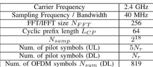
TABLE I: Measurements parameters
Carrier Frequency 2.4 GHz Sampling Frequency / Bandwidth 40 MHz FFT/IFFT size NF F T 256
Cyclic prefix length LCP 64
Nsamp 218
Num. of pilot symbols (UL) 5Nr
Num. of pilot symbols (DL) Nr
Num. of OFDM symbols Nsym(DL) 819
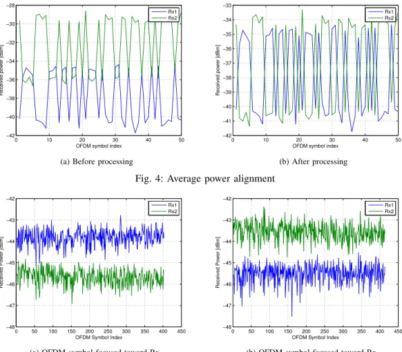
when the Tx board triggers a signal. Due to the propagation delay, the first recorded samples are simply due to noise. The frame detection is achieved when the received power of the incoming frame is above the noise level plus a margin of 10 dB. After the frame detection, an average is performed in the time domain to obtain the average power for each received OFDM symbol.
Fig. 4a indicates, for each Rx antennas, the average power of the 50 first received OFDM symbols for a line of sight (LOS) MIMO 4x2 configuration. On both curves, we can observe a power variation between two levels depending on the type of antenna to consider, i.e., if it is the target or not.
Indeed, we can observe that when the received power on
Rx1increases, the power received on Rx2decreases. However,
the average power for all the OFDM symbols received by Rx1
is smaller than the one of Rx2 due to a different path loss.
In order to compensate this path loss a power alignment is performed. It consists in translating incoming powers to the same range of values to correct the power difference that is due to the channel. The alignment is performed based on the DL pilot frame transmitted as previously explained in section III-B1. The first received symbol is a pilot that focuses on
Rx1. It is then possible to determine the maximum power value
obtained when Rx1is the target antenna. The remaining N r−1
symbols will also focus on the N r − 1 receive antennas. It is then possible to determine the minimum power value obtained
when Rx1 is not the target antenna. Knowing the maximum
and minimum power values enables to determine the average power. This operation is performed for every receive antenna and permits to evaluate the power differences between the receive antennas and to apply a compensation. Fig. 4b depicts the result obtained after power alignment. We can notice that, in order to determine the index of the target antenna for each OFDM symbol, it is sufficient to identify the antenna that receives the maximum power. Finally by subtracting one to the index of the target antenna and by converting the result to a binary sequence, it allows to retrieve the initial binary data which have been coded using the RASK modulator.
IV. RESULTS
In this section, several results are presented that deal with the impact of both the number of transmitting and receiving antennas on the overall RASK modulation performance.
The proposed testbed has been designed to be as flexible as possible. The parameters used during measurements are described in Table I.
TABLE II: ∆f values according to several configurations
Configuration Rx1 Rx2
2x2 LOS 1.85 dB 1.95 dB 2x2 NLOS 2.46 dB 2.22 dB 4x2 LOS 4.23 dB 4.14dB 4x2 NLOS 4.22 dB 5.06 dB
A. Impact of the numberNt of transmitting antennas
As a first study, a LOS configuration with Nt = 2 and
Nr = 2 is considered. The Tx antennas are distant 20 cm
away from each other and similarly for the Rx antennas. The distance between Tx antennas and Rx antennas is about 1.7 m.
Fig. 5 depicts the average power of the received OFDM
symbol on each Rx antenna, when the target antenna is Rx1
(5a) and Rx2 (5b), respectively. We can observe that, in both
cases, the power received by the target antenna is always greater than the received power by the other antenna, leading to no error after the RASK demodulation. When the target
is Rx1, the average ratio between the received power by the
target and the non target antenna is 1.85 dB and 1.95 dB when
the target is Rx2.
Note that errors occur if this difference become negative. Therefore, in order to evaluate the efficiency and robustness of the propose approach, we introduce a focus performance gain ∆f . This gain corresponds to the average power margin between the target antenna and the antenna with maximum received power among the non target antennas. According to this metric, it is then obvious that the bigger ∆f is, the easier the demodulation will be performed and the system will be robust.
The focus performance gain has been measured in 2 config-urations (2x2) and (4x2), in a LOS environment and in NLOS. Results are presented in table II.
According to Table II, it is clear that increasing the number of transmitting antennas significantly improves the perfor-mance of the RASK modulation in both configurations. This is due to one interesting property of TR which claims that
increasing Nt increases the spatial focusing efficiency and
therefore ∆f .
B. Impact of the numberNr of receive antennas
In this configuration, 2 receive antennas have been added to double the data throughput and verify the robustness of the RASK modulation. The same space of 20 cm between Rx antennas has been respected and the other antennas have exactly the same position as in the previous experiment.
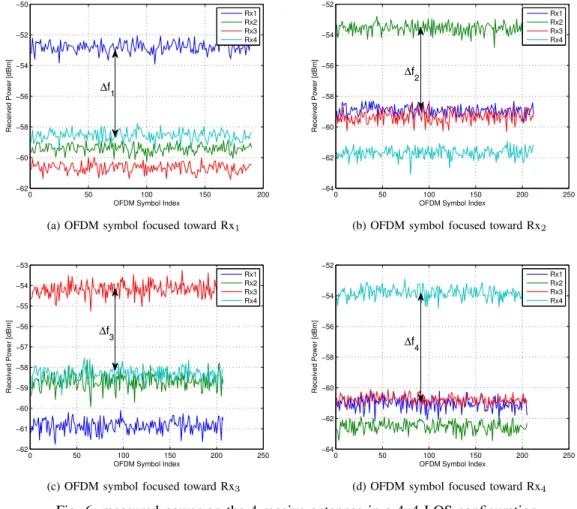
Fig. 6 depicts the average power of the received OFDM symbols that have been obtained on each antennas according to the target antenna. We can notice on the 4 cases that the maximum received power always corresponds to the target antenna and that it is quite simple to recover the transmitted data. Indeed, a very simple detector (threshold comparator) could be considered to retrieve the incoming sequence of bits. The bit error rate (BER) has been measured in this context and is equal to zero. Note that the same results have been obtained
0 10 20 30 40 50 −42 −40 −38 −36 −34 −32 −30 −28
OFDM symbol index
Received power [dBm]
Rx1 Rx2
(a) Before processing
0 10 20 30 40 50 −42 −41 −40 −39 −38 −37 −36 −35 −34 −33
OFDM symbol index
Received power [dBm]
Rx1 Rx2
(b) After processing
Fig. 4: Average power alignment
0 50 100 150 200 250 300 350 400 450 −48 −47 −46 −45 −44 −43 −42
OFDM Symbol Index
Received Power [dBm]
Rx1 Rx2
(a) OFDM symbol focused toward Rx1
0 50 100 150 200 250 300 350 400 450 −48 −47 −46 −45 −44 −43 −42
OFDM Symbol Index
Received Power [dBm]
Rx1 Rx2
(b) OFDM symbol focused toward Rx2 Fig. 5: measured power on the 2 receive antennas in a 2x2 LOS configuration in a NLOS configuration and for different distances between
the receive antennas. C. Use Case
We have evaluated the performance of RASK in a realistic scenario, i.e., an office environment. Figure 7 depicts the posi-tion of the transmitter and different posiposi-tions of the receiver in this environment. The transmitter, composed of 4 antennas, is placed in Tx. All antennas are 6 cm distant from each other. Similarly, the receiver is composed of 4 antennas with the same separation between antennas (6 cm). The measurement are performed for different positions of the receiver denoted
by Pos1,Pos2,Pos3,Pos4. Note that only Pos2 is in a LOS
configuration. Table III presents the obtained results in terms of the maximum focus performance gain ∆fmax and the minimum one ∆fmin. The BER is also provided for each configuration. According to this table, it can be seen that RASK performances are satisfactory in NLOS configurations but not in LOS. This is not only due to the absence of multi-paths which worsen the signal focusing but also to the small distance between the transmitting antennas which enlarges the beam shape. This has a direct impact on the power distribution and focusing.
TABLE III: ∆f values in a realistic scenario
Configuration Pos1 Pos2 Pos3 Pos4
∆fmax 6.95 dB 0.25 dB 1.38 dB 6.27 dB ∆fmin 4.13 dB 0.1 dB 0.004 dB 0.7 dB
BER 0 0.22 8.4.10−2 2.5.10−3
V. CONCLUSION
In this paper, we have proposed the first existing hardware prototype aiming at implementing the RASK modulation scheme on an FPGA platform. Performance has been evaluated according to different configurations (number of antennas at both transmitter and receiver side, LOS, NLOS). Finally, measurements have also been performed in a realistic scenario. Since the RASK demodulation is based on simple threshold comparators, it has been demonstrated that the proposed scheme makes it possible to consider very simple receivers in a MIMO configuration. Note that it can be usefully exploited in a massive MIMO scheme since the focusing capability is made even better as soon as the number of antennas increases at the transmitter side.
REFERENCES
[1] Y. A. Chau and S.-H. Yu, “Space modulation on wireless fading channels,” in Vehicular Technology Conference, 2001. VTC 2001 Fall. IEEE VTS 54th, vol. 3, 2001, pp. 1668–1671 vol.3.
0 50 100 150 200 −62 −60 −58 −56 −54 −52 −50
OFDM Symbol Index
Received Power [dBm] Rx1 Rx2 Rx3 Rx4 ∆f1
(a) OFDM symbol focused toward Rx1
0 50 100 150 200 250 −64 −62 −60 −58 −56 −54 −52
OFDM Symbol Index
Received Power [dBm] Rx1 Rx2 Rx3 Rx4 ∆f2
(b) OFDM symbol focused toward Rx2
0 50 100 150 200 250 −62 −61 −60 −59 −58 −57 −56 −55 −54 −53
OFDM Symbol Index
Received Power [dBm] Rx1 Rx2 Rx3 Rx4 ∆f3
(c) OFDM symbol focused toward Rx3
0 50 100 150 200 250 −64 −62 −60 −58 −56 −54 −52
OFDM Symbol Index
Received Power [dBm] Rx1 Rx2 Rx3 Rx4 ∆f4
(d) OFDM symbol focused toward Rx4 Fig. 6: measured power on the 4 receive antennas in a 4x4 LOS configuration
Tx
Pos_1
Pos_2 Pos_3
Pos_4
Fig. 7: Realistic scenario deployment
[2] S. Ganesan, R. Mesleh, H. Ho, C. W. Ahn, and S. Yun, “On the performance of spatial modulation OFDM,” in Signals, Systems and Computers, 2006. ACSSC ’06. Fortieth Asilomar Conference on, Oct 2006, pp. 1825–1829.
[3] M. A. I. F. Heliot and R. Tafazolli, “On the energy efficiency-spectral ef-ficiency trade-off over the MIMO rayleigh fading channel,” p. 13451356, 2012.
[4] A. Younis, N. Serafimovski, R. Mesleh, and H. Haas, “Generalised spatial modulation,” in Signals, Systems and Computers (ASILOMAR), 2010 Conference Record of the Forty Fourth Asilomar Conference on, Nov 2010, pp. 1498–1502.
[5] N. Serafimovski, A. Younis, R. Mesleh, P. Chambers, M. D. Renzo, C. X.
Wang, P. M. Grant, M. A. Beach, and H. Haas, “Practical implementation of spatial modulation,” IEEE Transactions on Vehicular Technology, vol. 62, no. 9, pp. 4511–4523, Nov 2013.
[6] D. T. Phan-Huy and M. H´elard, “Receive antenna shift keying for time reversal wireless communications,” in Communications (ICC), 2012 IEEE International Conference on, June 2012, pp. 4852–4856. [7] C. Masouros and L. Hanzo, “Dual layered MIMO transmission for
increased bandwidth efficiency,” IEEE Transactions on Vehicular Tech-nology, vol. PP, no. 99, pp. 1–1, 2015.
[8] A. Derode, P. Roux, and M. Fink, “Robust acoustic time reversal with high-order multiple scattering,” Physical review letters, vol. 75, no. 23, p. 4206, 1995.
[9] H. El-Sallabi, P. Kyritsi, A. Paulraj, and G. Papanicolaou, “Experimental investigation on time reversal precoding for space and time focusing in wireless communications,” IEEE Transactions on Instrumentation and Measurement, vol. 59, no. 6, pp. 1537–1543, June 2010.
[10] C. Zhou, N. Guo, and R. C. Qiu, “Time-reversed ultra-wideband (UWB) multiple input multiple output (MIMO) based on measured spatial channels,” Vehicular Technology, IEEE Transactions on, vol. 58, no. 6, pp. 2884–2898, 2009.
[11] “Warp project.” [Online]. Available: http://warpproject.org
[12] T. Dubois, M. H´elard, and M. Crussi`ere, “Time reversal in a MISO OFDMsystem: Guard interval design, dimensioning and synchronisation aspects,” in WirelessWorld Research Forum, WWRF-29), oct 2012. [13] G. S. Smith, “A direct derivation of a single-antenna reciprocity relation
for the time domain,” IEEE Transactions on Antennas and Propagation, vol. 52, no. 6, pp. 1568–1577, June 2004.
[14] T. Dubois, M. H´elard, M. Crussi`ere, and I. Maaz, “Time reversal applied to large MISO-OFDM systems,” in 2013 IEEE 24th Annual International Symposium on Personal, Indoor, and Mobile Radio Com-munications (PIMRC), sept 2013, pp. 896–901.