HAL Id: tel-00833250
https://tel.archives-ouvertes.fr/tel-00833250
Submitted on 12 Jun 2013HAL is a multi-disciplinary open access archive for the deposit and dissemination of sci-entific research documents, whether they are pub-lished or not. The documents may come from teaching and research institutions in France or abroad, or from public or private research centers.
L’archive ouverte pluridisciplinaire HAL, est destinée au dépôt et à la diffusion de documents scientifiques de niveau recherche, publiés ou non, émanant des établissements d’enseignement et de recherche français ou étrangers, des laboratoires publics ou privés.
Modélisation du transfert de charge dans les piles à
combustible
Giuseppe Mangiatordi
To cite this version:
Giuseppe Mangiatordi. Modélisation du transfert de charge dans les piles à combustible. Theoretical and/or physical chemistry. Université Pierre et Marie Curie - Paris VI, 2012. English. �NNT : 2012PAO66526�. �tel-00833250�
THÈSE DE DOCTORAT DE L’UNIVERSITÉ PIERRE ET MARIE CURIE
Présentée le 10 décembre 2012 par
Giuseppe Mangiatordi
Pour obtenir le grade deDOCTEUR de l’UNIVERSITÉ PIERRE ET MARIE CURIE
École Doctorale Chimie Physique et Analytique de Paris VI
Spécialité Chimie Informatique et Théorique
Modélisation du transfert de charge dans les piles à
combustible
devant le jury composé de :
M. Nicolas Ferré Rapporteur
M. Thomas Heine Rapporteur
M. Esmaïl Alikhani Examinateur
M. Damien Laage Examinateur
Mme Emilia Sicilia Examinateur
"More than machinery we need humanity; more than cleverness we need kindness and gentleness. Without these qualities, life will be violent and all will be lost." Charlie Chaplin
Remerciements
Tout d'abord, je tiens à remercier mon directeur de thèse M. Carlo Adamo qui m'a donné la possibilité de travailler dans son groupe de Modélisation des Systèmes Complexes. Il a eu confiance en mes capacités et il m'a permis de grandir beaucoup pendant ces années en me permettant de travailler de façon autonome.
Je remercie les rapporteurs M. Nicolas Ferré et M. Thomas Heine ainsi que les examinateurs M. Esmaïl Alikhani, M. Damien Laage et Mme. Emilia Sicilia pour avoir accepté de faire partie de mon jury.
Je vais garder un précieux souvenir de tous ces années et je vais me rappeler surtout des personnes que j'ai eu la grande chance de rencontrer à partir de tous ceux avec qui j'ai partagé la vie du laboratoire, établissement, souvent, une relation au-delà du domaine professionnel. Des remerciements particuliers vont à Ilaria et à Fred, pour leur disponibilité et leurs précieux conseils.
Je remercie vivement Valentina, non seulement pour notre amitié précieuse, mais aussi pour le soutien qu'elle m'a donné surtout dans la première partie de cette expérience. Je ne sais pas comment j’aurais pu affronter tous les problèmes initiaux sans son aide.
Je remercie aussi: Mario and son Renault Magnum 500CV, Giuseppe et ses ammantint
fort, Felix, Alessandro, Angela, Valeria, Violena, Simonetta, Pietro, Massimiliano, Daniele, Viviane
et Marion avec qui j'ai partagé de nombreux moments pendant ces trois dernières années.
Enfin, les remerciements les plus importants: à mes parents et { ma sœur, parce qu'ils n'ont jamais cessé de soutenir mes choix malgré les nombreux kilomètres qui nous séparent; et à Pia qui est tout simplement la meilleure chose qui me soit jamais arrivée.
Acknowledgments
First, I would like to thank my supervisor Prof. Carlo Adamo who has given me the opportunity to work in his group Modélisation des Systèmes Complexes. He has believed in my abilities and he has permitted me to grow during these years by allowing me to work independently.
I would also like to thank the rapporteurs Nicolas Ferré and Thomas Heine as well as the
examinateurs Esmaïl Alikhani, Damien Laage and Emilia Sicilia for agreeing to be a part of my
thesis committee.
I will remember with pleasure these years especially because of the people I have had the great fortune to meet, including all with whom I shared laboratory life often establishing a relationship beyond the professional field. Special thanks go to Ilaria and Fred, for their availability and their valuable advice.
I deeply thank Valentina, not only for our precious friendship, but also for the support she gave me in the first part of this experience. I do not know how I could have faced all the teething problems without her help.
I also want to thank: Mario and his Renault Magnum 500CV, Giuseppe and his ammantint
fort, Felix, Alessandro, Angela, Valeria, Violena, Simonetta, Pietro, Massimiliano, Daniele, Viviane
and Marion with whom I shared many moments worth remembering during these last three years.
Finally, the most important thanks: to my parents and my sister, because they never stopped supporting my choices despite those which put distance between us; and to Pia, simply the best thing that ever happened to me.
Ringraziamenti
Un primo doveroso ringraziamento va al mio direttore di tesi, Prof. Carlo Adamo che mi ha dato la possibilità di lavorare nel suo gruppo di Modélisation des Systèmes Complexes. Ha creduto nelle mie capacità e mi ha permesso di crescere molto in questi anni consentendomi di lavorare autonomamente.
Ringrazio i rapporteurs Nicolas Ferré e Thomas Heine e gli examinateurs Esmaïl Alikhani, Damien Laage ed Emilia Sicilia per aver accettato di far parte della mia commissione di tesi.
Ricorderò con piacere questi anni soprattutto per le persone che ho avuto la fortuna di incontrare a partire da tutti coloro con cui ho condiviso la vita di laboratorio instaurando, spesso, un rapporto che è andato al di là dell'ambito professionale. Un ringraziamento speciale va ad Ilaria e a Fred per la loro disponibilità e i loro preziosi consigli.
Ringrazio profondamente Valentina non solo per la nostra preziosa amicizia ma anche per il supporto che mi ha dato soprattutto nella prima parte di questa esperienza. Non so come avrei potuto affrontare tutte le difficoltà iniziali senza il suo aiuto.
Ringrazio inoltre: Mario e il suo Renault Magnum 500CV, Giuseppe e i suoi ammantint
fort, Felix, Alessandro, Angela, Valeria, Violena, Simonetta, Pietro, Massimiliano, Daniele, Viviane
e Marion con cui ho condiviso molti dei momenti cui vale la pena ricordare durante questi ultimi tre anni.
Infine i ringraziamenti più importanti: ai miei genitori e a mia sorella, per non aver mai smesso di sostenere le mie scelte nonostante queste portassero alla mia lontananza da loro; e a Pia, semplicemente ciò che di piu bello mi sia mai capitato.
CHAPTER I: BACKGROUND AND OBJECTIVES... 1
1. The Hydrogen Economy... 1
1.1. Hydrogen production ... 2
1.2. Hydrogen storage ... 4
1.3. Hydrogen use ... 5
2. Fuel cells: working principle ... 5
2.1. High temperature fuel cells ... 7
SOFC ... 7
MCFC ... 9
2.2. An example of low temperature fuel cell: the proton exchange membrane fuel cell (PEMFC) 10 Working principle and applications ... 10
Reducing catalyst poisoning ... 13
Increasing the catalyst activity ... 13
Increasing operative temperature ... 13
A PEMFC subcategory: DMFC ... 14
2.3. Other low temperature fuel cells ... 15
AFC ... 15
PAFC ... 16
3. The key component of PEMFCs: the Proton Exchange Membrane ... 17
3.1. Mechanisms of proton transport in PEMs ... 17
3.2. Other desired properties of the membrane ... 18
3.3. The PEM state of the art: Nafion ... 19
Limitations ... 21
3.4. Alternatives PEMs for high temperature PEMFCs ... 22
3.5. Azoles and azole-based polymers as proton conductors ... 23
Azoles as liquid solvents ... 23
Azole-based polymers as anhydrous proton conductors ... 24
4. Objectives ... 26
5. References ... 29
CHAPTER II: THEORETICAL BACKGROUND ... 41
1. Quantum Mechanics (QM) ... 41
1.1. The Schrödinger equation ... 41
1.2. The Born-Oppenheimer approximation ... 42
1.3. Molecular orbital (MO) approximation and basis functions ... 42
1.4. The Hartree-Fock Theory ... 44
The Hartree-Fock Equations ... 44
1.5. The correlation energy ... 46
1.7. The Coupled-Cluster (CC) theory ... 49
1.8. The Density Functional Theory ... 50
The Hohenberg-Kohn theorems ... 51
The Kohn-Sham method ... 52
Exchange-correlation Functionals ... 53
1.9. Statistical thermodynamics and partition function ... 55
Electronic partition function ... 56
Translational partition function ... 56
Rotational partition function ... 56
Vibrational partition function ... 57
2. Molecular Mechanics (MM) ... 57
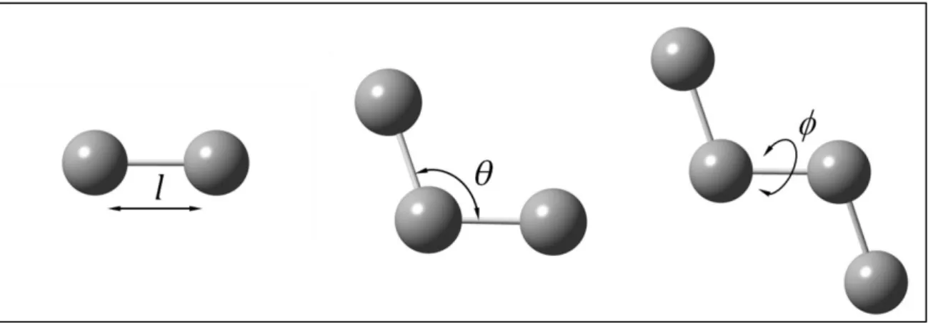
2.1. Force Field... 58
2.2. Molecular Dynamic simulations ... 60
Basic principle ... 60
The Verlet integration algorithm ... 61
Choosing the time step ... 62
The thermodynamic ensembles ... 62
Molecular Dynamics at constant temperature ... 63
2.3. Free energy calculations: the umbrella sampling technique ... 63
3. References ... 66
CHAPTER III: DFT STUDY OF PROTON TRANSFER REACTIONS ... 71
1. Modeling proton transfer in imidazole-like dimers... 71
1.1. Introduction ... 71
1.2. Methodological details ... 72
1.3. Identification of the PT reaction mechanisms ... 73
1.4. Basis Set selection... 74
1.5. The reference energy values ... 76
1.6. PT in imidazolium-imidazole complex ... 77
1.7. PT in 1,2,3-triazolium-1,2,3-triazole complex ... 79
1.8. PT in tetrazolium-tetrazole complex ... 80
1.9. Comments ... 84
1.10. The BMK/B3LYP model ... 87
2. PT reactions: a benchmark study... 88
2.1. Introduction ... 88
2.2. Methodological details ... 88
2.3. Results and discussion... 90
Proton transfer barriers at given structure... 91
Optimized structures: PT barriers & H-bond structural parameters ... 93
Comments ... 94
3. Conclusions ... 96
4. References ... 97
CHAPTER IV: STUDY OF PROTON TRANSPORT IN P4VI ... 105
1. Introduction ... 105
1.1. Poly-(4-vinyl-imidazole)... 105
1.2. The Brédas mechanism ... 106
2. Methodological details ... 108
3. Results and discussion ... 108
3.1. Conduction mechanism in small models: DFT investigation ... 108
Protonated dimers ... 108
Protonated trimer ... 111
3.2. Conduction mechanism in large models: molecular dynamics simulations ... 113
Force field parametrization ... 113
Analysis of the trajectory ... 114
3.3. A new charge-transport mechanism ... 119
3.4. Support from experimental evidences ... 123
3.5. Charges and electrostatic potential: support to the MD simulation quality ... 124
4. Conclusions ... 125
5. References ... 126
CHAPTER V: PROTON CONDUCTION OF H
3PO
4-DOPED P4VI ... 131
1. Introduction ... 131
2. Results and discussion ... 132
2.1. Identification of a Gotthuss chain in the starting complex ... 133
2.2. Proton transfer reactions in the protonated model ... 134
2.3. Investigation of the rate-limiting step ... 136
2.4. Comments ... 138
3. Conclusions ... 140
4. References ... 141
CHAPTER VI: PROTON TRANSPORT IN 2-TETHERED SYSTEMS ... 145
1. Introduction ... 145
2. Methodological details ... 147
3. Results and discussion ... 148
3.1. Conduction mechanism in small models: DFT investigation ... 148
Cooperative reorientation in a trimeric model... 150
3.2. Conduction mechanism in large models: Molecular Dynamics simulations ... 152
Force Field calibration ... 153
Analysis of trajectory ... 154
4. Comments and experimental evidences ... 157
5. Conclusions ... 159
6. References ... 161
GENERAL CONCLUSIONS ... 163
References ... 168
ANNEXES ... 171
ANNEX I: Supplementary information for chapter III ... 172
ANNEX II: Supplementary information for chapter IV ... 185
ANNEX III: Supplementary information for chapter VI ... 190
Synthèse générale ... 197
1. Contexte et objectifs ... 197
1.1. Les piles à combustible ... 197
La membrane d'échange de protons (PEM) ... 198
1.2. Les azoles et les polymères à base d'azoles comme conducteurs de protons ... 199
1.3. Objectifs de la thèse ... 200
2. Étude DFT des réactions de transfert de proton dans les azoles ... 201
2.1. Le modèle BMK/B3LYP ... 204
3. Une étude de référence de réactions PT ... 205
4. Étude du transport de protons dans P4VI... 207
4.1. Étude DFT du mécanisme de conduction dans les petits modèles ... 208
4.2. Étude MD du mécanisme de conduction dans les grands modèles ... 210
4.3. Un nouveau mécanisme de transport de charge... 211
5. Conduction protonique des P4VI dopés avec du H3PO4 ... 212
6. Transport des protons dans les systèmes avec attache en position 2 ... 213
6.1. Étude DFT du mécanisme de conduction dans les petits modèles ... 214
6.2. Étude MD du mécanisme de conduction dans les grands modèles ... 215
7. Conclusion générale ... 216
8. Références ... 218
Abstract ... 229
1
This chapter is devoted to the scientific and economic context of this thesis. In the first part, the main aspects related to the increasing use of Hydrogen as energy carrier will be presented. A general overview of the fuel cell technologies will be given in the second section while the last part will be focused on a detailed description of the design issues related to the Proton Exchange Membrane (PEM), key component of the Proton Exchange membrane Fuel Cells (PEMFCs) and object of the present theoretical study.
1. The Hydrogen Economy
Most of the environmental issues such as acid rain, stratospheric ozone depletion and global climate change are related to the production, transformation and use of energy. For instance, the global warming magnitude is strongly dependant on emissions of the so-called greenhouse gases (GHG)1 such as carbon dioxide, methane and nitrous oxide. Furthermore, it is expected that the
increasing of population with the consequent augmented request of food and energy could lead to an even increased dependency of the European Union and the US on oil imports. Notably, according to US Energy Information Administration’s International Energy Outlook 2011,2 the
global market for Energy consumption is estimate to grow almost 55% by 2035 (figure I-1). In the last years, these aspects have led to an increasing interest in renewable energies. In particular, one of the most promising alternatives to fossil fuel is Hydrogen. Indeed, Hydrogen energy systems are emerging as the one of the most successful solutions which can play a significant role in providing better sustainability and environment. Importantly, the use of Hydrogen to create the so called Hydrogen Economy (a future energy system based on Hydrogen and electricity) only requires technology, not political access. However, although hydrogen atoms are abundant and widely distributed throughout the world, they do not occur in nature as fuel H2 but in chemical compounds like water or hydrocarbons that must be chemically
transformed to produce it. Obviously, the hydrogen production from fossil fuels would deprive the hydrogen economy of much of its "raison d'être": it does not reduce the use of fossil fuels but rather shifts them from end use to an earlier production step still releasing carbon to the environment in the form of CO2. However, when made from non-fossil resources like water or
CHAPTER I: Background and objectives
2
Hoffman in his book "Tomorrow's Energy: Hydrogen, Fuel Cells and the Prospects for a Cleanest
Planet".3
Figure I-1: World marketed energy consumption, hystory (1990-2008) and projections (2015-2035). All data are in quadrillion Btu (British thermal unit). Source: US Energy Information Administration,
International Energy Outlook 2011.
As depicted in the figure I-2, the Hydrogen economy relies on a network composed of three functional steps: production, storage and use.4 Despite the great effort devoted in the last
few years, none of the several technical means used to achieve these steps can yet compete with fossil fuel in performance, cost and reliability. In this context, the possible future conversion of the world economy to the hydrogen will be possible only if a more and more in-depth basic research will be done in the next years.
1.1.
Hydrogen production
Molecular hydrogen is an energy carrier but not an energy resource, and therefore it must be produced first. Hydrogen can be produced using different methods. Currently the most widely used concern the electrolysis of water and the steam reforming of methane and other natural gasses.5 Biological production of H2 (biohydrogen) using microorganisms is an area of
technology development that offers the potential production of renewable H2 from biomass.6
Nevertheless, at the present about 50% of the global demand for H2 is produced by steam
reforming of natural gas, a process that is not considered sustainable since it leads to emissions of GHG. On the contrary, only a low percentage is made through green methods.7 Since this limit
depends on the low-efficiency and high-cost of the low-emission methodologies, a great effort has been made by both academic and industrial research to increase the rule of the green
3
hydrogen production. In this context, some examples are represented by recent methodologies such as water electrolysis plus concentrated solar power (CSP), Ocean Thermal Energy Conversion (OTEC) power or wind power.8
Figure I-2: The Hydrogen Economy as a system of primary energy sources linked to multiple uses (adapted from 4).
Despite these efforts, the most promising and fascinating strategy to produce hydrogen seems to reside in biological methods which are able to produce H2 miming biochemical
reactions performed by plants of microorganisms and without any emission of GHG. For instance, some green algae convert sunlight into water, hydrogen and oxygen while through microorganisms such as some Cyanobacteria, H2 is made by two photosynthesis reactions:
i)12H2O + 6CO2 → C6H12O6 + 6O2
ii) C6H12O6 + 12H2O→ 12H2 + 6CO2
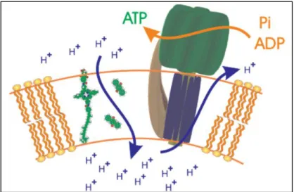
Even though these attractive technologies are still far to be competitive due to their high cost, a great progress has been achieved in the last few years. For instance, a molecular biodevice capable to use an enzyme to produce adenosine tri-phosphate (ATP, which is able to produce hydrogen directly from the substrate) through an artificial photosynthetic membrane (Figure I-3) has been developed at the Arizona State University9 whereas Levin and Chanine in a
recent review10 evidence the importance of methods mainly based on fermentation, such as
photo and dark-fermentations, pointing out that "although biohydrogen technologies are still in their infancy, developing technologies offer potential for practical application".
CHAPTER I: Background and objectives
4
Figure I-3: Schematic representation of an artificial photosynthetic membrane obtained in a liposome vesicle (adapted from9).
1.2.
Hydrogen storage
Obtaining a safe technology for hydrogen storage at room temperature is nowadays considered one of the major obstacles in the Hydrogen Economy, especially for the development of fuel cells for automobiles. Although different methods of hydrogen storage have been applied in the last years, none of them have completely satisfied the indicated standard of the US Department of energy considering economic as well as environmental parameters.11
Today the available technologies permit directly to store hydrogen through chemical or physical combination with several materials or by modifying its physical state in gaseous (pressurized gas) or liquid (cryogenic liquid). Nevertheless, these last two methods are hindered by the H2 physico-chemical properties. Indeed, because of the low boiling point (20.28 K) liquid
hydrogen requires addition of a refrigeration unit to maintain a cryogenic state, a process which is very expensive. Concerning the storage in gaseous phase, the very low density (0.08988 g/L at 1 atm) makes necessary the use of high-pressures, a process complicated by the weight of the canisters and the possible leaks. For these reasons, a great effort has been done in the last years to develop methods able to store hydrogen through the combination with other materials so that today different methodologies can be used: 1) adsorption on materials with a large specific surface area,12 2) adsorption in interstitial sites in a host metal,13 3) bonding in covalent and
ionic compounds14 and 4) oxidation of reactive metals (Zn, Li, Mg, Al, Na) with water.15,16 This
last method allows for the highest densities of hydrogen and offers a very safe and efficient way to store it. For instance, 6.5 H atoms are stored in each cm3 of MgH216 in spite of 0.99 in hydrogen
gas and 4.2 in liquid hydrogen.17 It is believed that further scientific research and technical
developments will lead to new materials with values of hydrogen density close to 300 kg/m3
5
1.3.
Hydrogen use
After being produced and properly stored, Hydrogen is ready to be utilized. Notably, it can provide energy in two different ways: i) combustion ii) through fuel cells.18,19
The combustion is mainly used for transport applications. Hydrogen can be, in fact, burned in an internal combustion engine in the same way as non-renewable fuels such as petrol or diesel in order to power vehicles. This process produces water as the main byproduct, but also small amounts of oxides of nitrogen which is an air pollutant.
In contrast, fuel cells are suitable for a wide range of applications going from stationary power generators to laptops and mobile phones. Furthermore they assure higher efficiency with respect to combustion based devices (45% vs 25%19). This technology is, therefore, considered
of choice for a possible future Hydrogen Economy.
2. Fuel cells: working principle
The fuel cells are devices used to produce electricity from different fuels. In spite of their recent development, they represent one of the oldest electrical energy conversion system known to man. Their invention is attributed, indeed, to Sir William Grove, a Professor at the university of Brasle who in 1852 summarized the fuel cell principle in the following famous words: “Every
chemical synthetic action may by a proper disposition of the constituents be made to produce a voltaic current”.
All fuel cells have the same basic operating principle and their core consists of two electrodes and one electrolyte. At the negative anode the fuel is oxidized while at the positive cathode the oxygen is reduced and ions are transported from one side to the other through the electrolyte (Figure I-4). In other words, a fuel cell operates as a galvanic cell in which the free energy of a chemical reaction is converted into electrical energy. Notably, if we consider n electrons involved in the reaction, the Gibbs free energy change is related to the cell voltage via:
G -nF U o
(I-1) where F is the Faraday constant and ∆Uo is the voltage of the cell for thermodynamic equilibrium
in the absence of a current flow.
The electrochemical reactions occurring in a fuel cell (oxidation at the anode and reduction at the cathode) would occur very slowly in absence of a catalyst which is therefore critical to ensure the correct operation of these devices.20 Such a catalyst, which covers each of
the electrodes, is usually made of platinum powder very thinly coated onto carbon paper or cloth. Furthermore, in order to have the maximum surface area of the platinum exposed to the hydrogen or oxygen, the catalyst is porous and rough.21 However, the efficiency of a catalyst in a
CHAPTER I: Background and objectives
6
problems especially when the fuel is hydrogen since high levels of purity are obtained only after very expensive and difficult processes.
The key component of a fuel cell is the electrolyte which determines the temperature window of operation. Consequently fuel cells are named after their electrolyte material and are commonly classified into two main groups depending on the temperature operation:
- Low-temperature fuel cells operating at temperatures < 250°C such as alkaline (AFCs), polymer electrolyte membrane (PEMFCs) and phosphoric acid (PAFCs) fuel cells.
- High-temperature fuel cells operating at > 500 °C such as solid oxide (SOFCs) and molten carbonate (MCFCs).
Figure I-4: Working principle of a generic fuel cell (the solid electrolyte is here represented by a membrane).
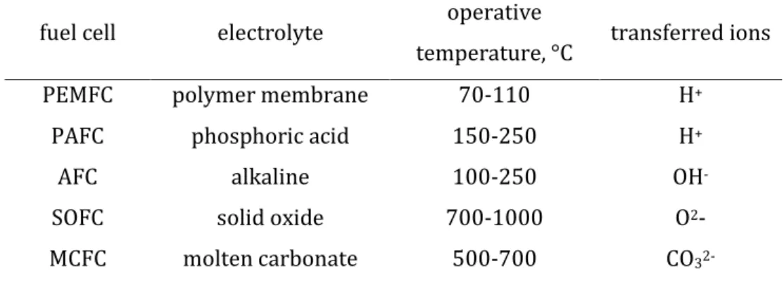
As shown in table I-1, all fuel cells operate through reactions in which ion species migrate through the electrolyte membrane: protons (H+) in PEMFC and PAFC, hydroxyl ions (OH
-) in AFC, oxide ions (O2-) in SOFC and carbonate ions (CO32-) in MCFC.
The growing interest of the last few years in these devices has been due to their capacity to convert Hydrogen in electricity without any GHG emission and producing only water as by-product. Nevertheless, after more than 150 years from their invention, a strong technical progress able to reduce the cost is still necessary for a large scale commercialization which can
7
be optimistically obtained in the near future. Obviously, the high cost can be reduced only if substantial investments and strong research effort in fuel cell development will be made in the next years.
Table I-1: Electrolyte, operative temperature and transferred ion for each of the different types of fuel cells (Adapted from23).
fuel cell electrolyte operative
temperature, °C transferred ions
PEMFC polymer membrane 70-110 H+
PAFC phosphoric acid 150-250 H+
AFC alkaline 100-250 OH
-SOFC solid oxide 700-1000 O2-
MCFC molten carbonate 500-700 CO
32-The different suitability for particular applications depends on different characteristics mainly due to the operative temperatures. PEMFC and PAFC are well matched to transport and mobile applications thanks to the fast start-up, whereas high-temperatures fuel cells are better suites as stationary power generators because of the longer time to arrive at operating temperature. A brief overview of the different fuel cells technologies will be given in the following with particular attention devoted to advantages and disadvantages relative to each other as well as on their different suitability.
2.1.
High temperature fuel cells
SOFC
The solid oxide fuel cells (SOFCs) are the oldest devices of the family. The solid oxide electrolyte, basic component from which they were conceived, was discovered in 1899 by Nernst who reported the different conductivity between pure metal oxides (very low even at high temperatures) and the mixtures of metal oxides which can possess dramatically higher conductivity.24 Notably, he pointed out the coherence of these results with the behavior of liquid
electrolyte where the conductivities of aqueous salt solutions are much higher than pure water and pure common salt. Mixed oxides which exhibit high conductivity at elevated temperatures were therefore identified including the composition 85% zirconium oxide and 15% yttrium oxide, particularly favorable as patented by Nernst himself. Only six years later the first patent on fuel cells with a solid electrolyte (using porcelain and glass) was filed by Haber.25
CHAPTER I: Background and objectives
8
In the following years, the development of SOFC was significantly hampered by serious materials problems especially related to the high operating temperature and to the reducing nature of the fuel gas. A renewed interest in this technology is evident only after 1960 due to various factors such as the progress in preparation and production of ceramic materials and the general interest in fuel cell technology as "environmental friendly".
Figure I-5: Concept diagram of SOFC (adapted from26).
SOFC are also the only fuel cell in which the charge transport in the electrolyte involves negatively oxygen ions (O2-) (Figure I-5). Notably, in the case of pure H2 as fuel, the chemical
reactions occurring during the operation are the following: i) Anode reaction: 2H2 + 2O2- → 2H2O + 4e–
ii)Cathode reaction: O2 + 4e– → 2O
2-iii)Overall cell reaction: 2H2 + O2 → 2H2O
At the cathode the oxygen gas reacts with electrons to create oxygen ions which then cross the electrolyte to react with hydrogen gas at the anode where electricity and water is produced. It is worth to underline that also carbon dioxide (CO2) can be a product of SOFC for
instance using hydrocarbons which are converted into carbon monoxide (CO) and hydrogen (H2)
at the anode. In this case the reactions can be expressed as in the following: i) Anode reaction: CO + H2 + 2O2- → CO2 + H2O + 4e–
ii) Cathode reaction: O2 + 4e– → 2O
2-iii) Overall cell reaction: H2 + CO + O2 → H2O + CO2
Nevertheless, the carbon emissions from an SOFC system are less than those from a fossil fuel combustion.27
9
Concerning the technological aspects of this device, the peculiarity is represented by the high temperatures used (conventionally between 700-1000°C) which leads to several effects. For instance, in case of using hydrocarbon fuel, thanks to the high temperatures, an internal reforming of the fuel is possible so that the hydrocarbon is catalytically converted to carbon monoxide and hydrogen within SOFC. This reduces the costs and the complexity of the system. The tolerance to carbon monoxide and in general to impurities represent another advantage of SOFC which markedly contrasts with other types of fuel cells like PEMFC which for instance requires expensive and complex systems to contrast the CO poisoning (for a short discussion on that see section 3.3).
Despite these advantages, since high temperatures are necessary, SOFCs are not suitable for a large range of applications where a rapid start up and cool down is essential such as mobile devices and transportation. In contrast, they represent the most suitable fuel cells for applications in the distributed generation market (stationary power) because of their high conversion efficiency.28,29
MCFC
Like SOFCs, the molten carbonate fuel cells (MOFCs) are high-temperature fuel cells, with an operative temperature of about 600°C. In such devices the electrolyte is a molten lithium potassium carbonate salt suspended in a ceramic matrix of beta-alumina solid (BASE) which is porous and chemically inert. Figure I-6 illustrates the working principle of a MOFC.
The molten state of the electrolyte allows for the movement of the negative carbonate ions within the cell. Notably, the chemical reactions occurring during the operation are the following: i)Anode reaction: 2CO3-2 + 2H2 → 2H2O + 2CO2 + 4e-
ii)Cathode reaction: 2CO2 + O2 + 4e- → 2CO3-2
iii)Overall cell reaction: 2H2 + O2 → 2H2O
The hydrogen fuel reacts with the carbonate ions available in the electrolyte to give carbon dioxide, water and electrons while the reduction happening at the cathode produce new carbons ions which are then transferred to the anode. As in SOFCs, since the high operating temperature dramatically improves reaction kinetics, a non-expansive catalyst can be used. The elevated operative temperature also makes the cell less prone to carbon monoxide poisoning than other fuel cells systems and prevent the need for an external reformer. One disadvantage associated with MCFCs concerns the necessity to inject carbon dioxide at the cathode as carbonate ions are consumed in reactions occurring at the anode. Furthermore, the presence of carbonate ions together with the high temperatures lead to a fast corrosion at the MCFC components and to a consequent very short cell life, considered one of the mayor limits of these devices.30 Regarding the applications, like SOFCs, MCFCs are used in large stationary power
CHAPTER I: Background and objectives
10
generation whereas they are not suitable for mobile applications because of the high operative temperature.29
Figure I-6: Concept diagram of MOFC (adapted from26).
2.2.
An example of low temperature fuel cell: the proton exchange membrane
fuel cell (PEMFC)
Working principle and applications
The distinguish features of a PEMFC are the use of a polymer membrane (PEM) as electrolyte and the low operative temperature range (50-100°C). The occurring reactions can be expressed as in the following:
i) Anode reaction: 2H2 → 4H+ + 4e
-ii) Cathode reaction: 02 + 4H+ + 4e- → 2H2O
iii) Overall reaction: 2H2 + 02 → 2H2O
The Hydrogen is activated by a catalyst to form electrons and protons. These last are the charge carriers of the system: they permeate through the polymer membrane from the anode to the cathode side. Here they react with the liberated stream of oxygen and the electrons arriving through the external circuit to give water as product (figure I-7)
Basically the PEMFC is comprised of (i) electrode-bipolar plates (ii) catalyst and (iii) PEM (figure I-8). The electrode-bipolar plates act as anode for one cell and as cathode for the adjacent cell and can be made by different materials such as metal, graphite, carbon-polymer composites and others.31 Moreover they usually incorporate flow channels for the fluids feeds.
The core of the system is represented by the so called membrane electrolyte assembly (MEA) which consist of the proton conducting membrane between two carbon papers coated with the
11
catalyst. Thanks to the presence of a immobilized electrolyte these devices are shock and vibration tolerant. This feature together with the fast startup and the instantaneous response to changes in demand for power make them the most promising type of fuel cell for transportation and mobile applications.32
Figure I-7: Concept diagram of PEMFCs (adapted from26)
Nowadays most of the motor companies using fuel cells technology use solely PEMFC. Notably, automakers such as General Motors (GM), Hyundai, Honda, Daimler and Toyota, have proclaimed plans for commercializing their PEMFC vehicles by 2015.34 Figure I-9 shows some
prototypes using PEMFC technology. Considering the fast-growing energy demand of the modern portable electric devices such as laptops or cell phones as well as the limited energy capacity of the current batteries, another promising area for PEMFCs is the portable electronics. Major electronics companies, such as Toshiba, Sony, Motorola, LG, and Samsung, have set up research units for portable fuel cells. The main advantage in this field concerns the ability of PEMFCs to provide continuous power as long as hydrogen fuel efficiency loss.32
Despite these efforts, barriers to their world-wide commercialization still exist mainly because of the low durability and the high cost.34 Further scientific breakthroughs in the field are
therefore required mainly in material development and in improved understanding of PEMFC operation principles. Much of the current research topics in PEMFCs can be classified following few objectives:
- reducing the poisoning of the catalyst by impurities gas.
CHAPTER I: Background and objectives
12 - obtaining high temperature PEMFCs (HT-PEMFCs).
Figure I-8: The PEMFC components (adapted from33)
13 Reducing catalyst poisoning
As above mentioned, the hydrogen gas is produced mainly using steam reforming light hydrocarbons. This makes a mixture which also contains CO (1–3%), CO2 (19–25%), and
N2 (25%)35. Since they combine both activity and stability in the fuel cell environment,
Platinum-based electrocatalysts are still the only used catalyst materials. Nevertheless, the sensitivity of the platinum to the impurities (especially to carbon monoxide) strongly reduce the catalyst performance during the operation.36 Therefore, reduction of the concentration of CO in the fuel
and development of CO-tolerant electrocatalysts are considered among the most important factors to improve the performance of PEMFCs. Notably, current research is focusing on few ways to overcome the CO poisoning such as the use of CO tolerant catalysts, the oxidant bleeding into the fuel feed stream and the develop of membranes for the CO separation.37,38
Increasing the catalyst activity
Because of his high cost, the large amount of platinum needed for a PEMFCs is today considered one of the reasons for which PEMFCs are excluded from commercialization. As a consequence, one of the main aims of catalyst design consist of improving his catalytic activity. In this sense, one of the most investigated strategy consist of modifying the size and the shape of the platinum particles in order to maximize the available surface to participate in reactions.39
Another strategy concerns the synthesis of platinum nanocrystals with high-index planes which exhibit much higher catalytic activity than that of the most common stable planes.21
Increasing operative temperature
Several technical advantages can be obtained working at temperatures beyond the typical temperature range (50-100 °C).40 Indeed, It has been shown that the catalyst poisoning
effect strongly depends on the operative temperature.41 For instance, at CO concentration of 100
ppm, a cell temperature of at least 100 °C is required for having CO tolerance while an operative temperature of 140°C makes the poisoning effect almost negligible.42 This dependence has been
explained considering the strong temperature reliance of the adsorption equilibrium constant of CO on the catalyst since this interaction is associated with high negative entropy.
Advantages related to heat management can also be obtained. The 40-50% of the energy produced by a PEMFC, in fact, is heat that must be removed quickly to avoid overheating problems.43 For PEMFCs operating at low temperatures the heat rejection velocity of the
conventional automotive radiators is insufficient to reject continuous full power waste heat so that a complex, weight and very large system is required. On the contrary, the cooling systems utilized for internal combustion engine (ICE) vehicles are sufficient for PEMFCs working at high temperatures so obtaining an improvement in terms of weight- and mass-specific energy densities of the system.44 Furthermore the produced excess heat can be recovered as steam
CHAPTER I: Background and objectives
14
which can be used for direct heating or for pressurized operations. For instance, it has been shown that under an operating temperature of about 200 °C, the fuel cell stack can produce a water steam of up to 15 atm44 leading to a significantly increased efficiency.
In addition to the heat management, also a carefully and often difficult water management is necessary during the operation of a low-temperature PEMFC.44 Indeed, since in a
low temperatures scenario a dual-phase water system is involved (liquid water/ vapor water), in high humidity conditions the electrodes can be flooded thus effecting the durability of the system.45,46 Under temperatures above the boiling point of water, the flooding problem is
avoided and therefore the water management significantly simplified. Finally, thanks to the elimination or reduction of liquid water, an increasing of exposed surface area of the electrocatalysts is obtained as well as a better diffusion of the reactants in the reaction layer.47
Another technical advantages of the high temperatures PEMFCs concerns the electrode reaction kinetics. Indeed, working at high temperatures the reaction kinetics of both hydrogen oxidation and oxygen reduction reactions can be enhanced.40,48 Especially the latter is
considered crucial to improve the performance of a PEMFC since, being slow, it determines the overall electrochemical kinetics of the systems. It is believed49,50 that thanks to the enhanced
kinetic obtained working at higher temperatures, the necessity of using platinum catalyst (one of the mayor obstacle which makes PEMFCs non competitive) could be overcame with a consequent significant reducing of the system total cost.
A PEMFC subcategory: DMFC
A particular type of PEMFC is the direct methanol fuel cell (DMFC). This device uses methanol instead of hydrogen as power source:
i) Anode reaction: 2CH3OH + 2H2O → 2CO2 + 12H+ + 12e-
ii) Cathode reaction: 3O2 + 12e- + 12H+ → 6H2O
iii) Overall reaction: 2CH3OH + 3O2 → 2CO2 + 4H2O
The main advantage respect to classical PEMFCs concerns the easy transportation of methanol which is stable at all the environmental conditions. Furthermore, these devices do not have many of the fuel storage problems typical of fuel cells because methanol has a higher energy density than hydrogen. Nevertheless, because of the so-called methanol cross-over (methanol diffusion through the membrane without any reaction), the fuel is fed as a weak solution so that the efficiency of these systems is very low.51 This disadvantage makes them
targeted only to a restricted range of portable applications where power and energy density are more important than efficiency.52
15
2.3.
Other low temperature fuel cells
AFC
The Alkaline Fuel Cells (AFC) are devices typically performing at temperatures between 60 and 90 °C. The electric power is generated utilizing as electrolyte a porous matrix saturated with an aqueous alkaline solution such as potassium hydroxide (KOH). As depicted in figure I-10, the ions travelling across the electrolyte are the hydroxyl ions which react at the anode with two molecules of hydrogen to release 4 water molecules and 4 electrons:
i) Anode Reaction: 4OH- + 2H2 → 4H2O + 4e
The electrons flow through the external circuit and react with water to produce new OH- ions:
ii)Cathode Reaction: O2 + 2H2O + 4e- → 4OH
-The overall reaction is given by:
iii)Overall Cell Reaction: 2H2 +O2 → 2H2O
Figure I-10: Concept diagram of AFCs (adapted from26)
Several advantages characterize such device with respect to the other fuel cells. Since the used electrolyte is potassium hydroxide, a very cheap chemical standard, AFCs are the most cost efficient type of fuel cells. Furthermore they have no GHG emissions and the potential efficiency is the highest among the others fuel cells technologies (estimated at 60%).53 Despite these
advantages, the use of AFCs is still very limited. Indeed, differently from the other types of fuel cells, in AFC only pure hydrogen can be used as a fuel. Furthermore, the alkaline solution (KOH) used as electrolyte is able to absorb carbon dioxide (conversion of KOH to potassium carbonate K2CO3) with the consequent poisoning of the cell. During the operation, therefore, air needs to
CHAPTER I: Background and objectives
16
whole system.54 Consequently, current research is focusing on finding a substitute of KOH.53
Because of this poisoning effect, AFCs are mainly used for spatial applications, where purifying air is not necessary.55
PAFC
The phosphoric acid fuel cells (PAFCs) have an operative range that is about 150°C-210°C. They use liquid phosphoric acid (H3PO4) saturated in a silicon carbon matrix as
electrolyte whereas the carbon paper is used to make the electrodes which are covered by platinum catalyst. As shown in the figure I-11, the hydrogen at the anode splits into 4 protons and 4 electrons which at the cathode combine with oxygen to form water. In this case the charge carrier is the proton H+:
i) Anode reaction: 2H2→ 4H++ 4e-
ii) Cathode reaction: O2 + 4H+ + 4e- → 2H2O
iii) Overall reaction: 2H2 + O2→ 2H2O
Figure I-11: Concept diagram of PAFCs (adapted from26)
The expelled water is usually used in heating applications by conversion to steam thus increasing the efficiency of the system. Differently from AFCs, for which only pure H2 can be used
as fuel, PAFCs can operate with a larger choice of fuels. Indeed, CO2 does not affect the
electrolyte. However, the applicably of these devices is limited by the short range of operative temperature (150-210 °C). Indeed, at temperatures lower than 150°C phosphoric acid is a poor proton conductor and the poisoning of the platinum catalyst at the anode became severe. On the other hand, high temperatures create structural design problems, particularly for joints,
17
supporting pumps, and sensors mainly due to the aggressive hot phosphate. Their characteristics are therefore compatible only with a limited scale of on-site stationary applications.56
3. The key component of PEMFCs: the Proton Exchange Membrane
It is commonly accepted that the commercialization and competitiveness of PEMFCs will depend on continuous innovation and improvement of its key component: the proton exchange membrane (PEM).40,57,58 Notably, the basic requirements for a PEM are the absence of an
electronic conductivity and the presence of an high proton conductivity. Little concern is devoted to electronic conductivity because the polymer electrolytes typically employed are inherently electrically insulating. On the contrary, the proton conductivity is a very important tool for determining the performance or utility of a membrane as a candidate for PEMFCs. Notably, levels of conductivity at least above 0.01 S/cm are required. In a fuel cell system, such a value is measured using the following equation:
L Rdw/(
I-2)where L is the distance between the electrodes, R is the measured resistance and d and w are respectively the thickness and width of the membrane. Obviously, high levels of proton conductivity can be achieved only if the membrane is able to efficiently transport the protons from the anode to the cathode side, a process which can occur by means of different mechanisms.
3.1.
Mechanisms of proton transport in PEMs
Proton transport in PEMs can be carried out either by a vehicle mechanism diffusion59 or
by a structural diffusion (also named Grotthuss mechanism60,61).
Figure I-12: Models of proton conduction. Top: Vehicle Mechanism; the protons transfer through a moving vehicle. Button: Grotthuss mechanism; the protons are passed through the cooperation of
CHAPTER I: Background and objectives
18
The former takes place with the aid of a moving "vehicle" (Figure I-12, top). In other words, the excess protons migrate through the membrane carrying small molecules with them. An example is given by the migration of H3O+ in hydrated membranes.
With the Grotthuss mechanism (Figure I-12, button), the proton diffuses through proton displacement (also termed proton "hopping") and molecular reorientation. Notably, the proton conduction occurs through the formation and cleavage of H-bonds between neighboring molecules. Such a mechanism is named Grotthuss mechanism, since it was firstly proposed in 1806 by Theodor Grotthuss60 who described the passing of protons in water as a cooperation of
neighboring water molecules (Figure I-13).
Figure I-13: Schematic representation of Grotthuss mechanism in water.
If proton conductivity through vehicle mechanism is mainly affected by the mobility of the used vehicle (e. g. H2O or NH3 as complexes H3O+ or NH4+), the major aspects governing the
proton conductivity in the Grotthuss mechanism are still unclear even if it is commonly accepted that dynamic hydrogen bonds are desired in order to enhance the local mobility which is crucial to reach high level of proton conductivity through structural diffusion.57
3.2.
Other desired properties of the membrane
Together with an high proton conductivity, also chemical and mechanical stability are considered vital for PEMs. Indeed, they are closely related to the PEM durability which is still one of the critical issue impeding the commercialization of PEMFC. Notably, membrane degradation can be classified into three categories: mechanical, thermal and chemical/electrochemical.62 The early life failure is mainly due to the mechanical degradation
which can be, for instance, the effect of the overall dimensional change occurring during the operation and due to the resulting non-humidification or low humidification of the membrane.
63,64 Furthermore, the PEM mechanical strength can be negatively affected by the migration and
accumulation of the catalysts and by the decomposition of the seal into the membrane. Since a rapid start-up and an efficient cooling system are essential for automotive and portable applications, the membrane must tolerate freezing temperatures as well as thermal cycling. Several studies65-67 have evidenced as the thermal stability issue of some PEMs is directly related
19
to the presence of water in the membrane. Indeed, the PEM's lifetime can be strongly affected by the volume change of water due to freeze/thaw cycles occurring during the operation.
The lifetime of the membrane can be also affected by the chemical/electrochemical instability. Indeed, the chemical reactions on the anode and cathode catalyst can produce peroxide and hydroperoxide radicals which are responsible of a chemical attack to the membrane whereas the rate of hydrogen and air crossover to opposite sides of the membrane causes only the 1-3% loss in fuel cell efficiency.68 Together with the tolerability to radicals, also
the reactant permeability is an important property for PEMs. Indeed, although the hydrogen and oxygen permeability in polymer electrolyte materials are typically low, they can affects the lifetime especially of ultra-thin membranes. Furthermore, as mentioned describing a subcategory of PEMFCs (DMFCs), also the PEM methanol permeability can represent a significant problem. It is much higher than reactant gas permeability and leads to significant performance losses due to the decrease of the overall fuel efficiency and to the impact on the cathode kinetics.51
Even though the membranes currently used fulfill many of the required properties, the projected PEMs cost has to be reduced drastically before having PEMFCs commercially feasible. Indeed, the strong PEMFC cost reduction of the last years (more than 35% from 2007 to 200969)
is mainly due to the auxiliary facilities and catalyst while the membrane cost in nearly unchanged because of the widely employing of expansive perfluorinated polymers, still today considered the only marketable PEMs for use in PEMFCs. Nafion (Dupont de Nemours70), Dow
(Dow Chemical71), Flemion (Asahi Chemical) or Aciplex-S (Asahi Glass72) are examples of
perfluorinated polymers marketed as PEMs. In spite of a great number of alternative polymer membranes developed,58,69 including nonfluorinated types, Nafion is still considered the
bench-mark material against which most results are compared.
3.3.
The PEM state of the art: Nafion
The devolvement of Nafion, a sulfonated tetrafluorethylene copolymer, began in the early 1960s when the DuPont Company's Plastics Exploration Research Group was expanding on fluorine technology.73 It is the progenitor of a class of synthetic polymers called ionomers and
represents the first perfluorosulfonic acid (PFSA) membrane used as PEM. As shown in figure I-14, it consists of flexible side chains terminated with hydrophilic sulfonic acid groups and a chemically durable hydrophobic backbone. Ion content can be varied by changing the ratio of the two components (x and y in figure I-14).
CHAPTER I: Background and objectives
20
Figure I-14: Chemical structures of Nafion, (adapted from58).
Because of the ionic nature of the SO3H groups, the ends of the sides tend to cluster
within the overall structure of the membrane. In 1977 Gierke and coworkers74 proposed a
Cluster-Channel Model for Nafion in which the neighboring ionic clusters are assumed to be connected by short narrow (Figure I-15). According to this model, the formed micelles, characterized by a 40 Å diameter, distribute continuous fluorocarbon matrix interconnected by narrow channels of about 10 Å in diameter. It is believed that this specific morphology and chemical structure is responsible of both the better proton conductivity and the higher lifetime compared to other materials.75
Notably, Nafion is commercially available in different weights. Among them, Nafion 117, characterized by a weight of 1100 EW and a thickness of 7 mil (1 mil equals 25.4 m), is currently the most widely used. Note that an equivalent weight (EW) corresponds to the weight of Nafion (in molecular mass) per mole of sulfonic acid group.76 The combination of weight and
thickness of Nafion 117 provides high proton conductivity (7.8 × 10⁻² S/cm at ambient
temperature77) and moderate swelling in water. Like other PFSAs, Nafion is quite resistant to
chemical attack whereas at high temperature ( > 80°) the mechanical strength is very low.
Figure I-15: Cluster-Channel Model of Nafion ( Adapted from78)
Like in the other PFSA membranes, the degree of hydration is the main factor which governs the proton conductivity in Nafion.77 At high humidity condition, the membrane can be
described as a two-phase system consisting of a network of water surrounded by a hydrophobic backbone (Figure I-16). This last provides the structural and thermal stability of the membrane
21
and it is also responsible for the immobilization of the dissociated sulfonic acid groups which are solvated in the interfacial region. During the process, catalytically produced protons act as defects and migrate through the membrane from the anode to the cathode carrying water molecules with them (H3O+ diffusion). Therefore the presence of this double-phase
(hydrophobic matrix and hydrophilic channel) is necessary to transport protons since the proton transport mechanism is basically conduction through water. However, the hydronium diffusion alone (vehicle mechanism) can't explain the mobility of protons in water which is much higher if compared with other ions of a size similar to H3O+. Such a difference can be
explained in terms of contribution by the so-called Grotthuss mechanism61 in which, as above
mentioned, the transport of protons is determined by forming and breaking process of hydrogen bonds between the neighboring molecules, in this case water molecules. In short, the conductivity of Nafion relies on the proton mobility in the hydrophilic channel where protons are carried through both Grotthuss and vehicle mechanisms.
Figure I-16:Proton transport in Nafion (Adapted from47) Limitations
One disadvantage of Nafion consist of the high cost (amounting to US$ 700 per square meter) so that it is commonly accepted that some sacrifice in material lifetime as well as in mechanical properties may be acceptable in order to develop materials having commercially realistic costs.
79
However, the major drawback of Nafion (and of the other PFSA membranes) is nowadays considered its inability to satisfy the requirements for the latest development of the PEMFC technology which consist of obtaining PEMs working at high temperatures (above 100 °C) which
CHAPTER I: Background and objectives
22
allow for some important technical advantages (see section 2.2). Indeed, while this membrane performs very well in a water saturated environment, proton conductivity decreases considerably at low relative humidity because of its reliance on water for proton conduction.77,80
Obviously, as the temperature increases, the water uptake decreases considerably with a consequent strong decline of the cell voltage and efficiency. This makes impossible an operation temperature above 80°C. Furthermore, the adsorbed water affects the mechanical properties of the membrane by acting as a plasticizer so that a careful control of water uptake is critical during the operation for reducing adverse effects of swelling and degradation.
3.4.
Alternatives PEMs for high temperature PEMFCs
There are various strategies for obtaining membranes working at low humidity and high temperatures.58,69 They can be divided in two main subcategories: i) Use of modified Nafion, ii)
Use of different starting materials. For instance, an improved performance of PEMFCs under low humidity conditions can be obtained incorporating into Nafion membrane mesoporous silica spheres81. Furthermore, Nafion can be modified incorporating diversified additives such as
fuctionalized silica82,83, modified carbon nanotubes,84 treated clays,85 zeolite,86 zirconia
nanoparticles,87 zirconium hydrogen phosfate88 and ionic liquids.89 Other strategies consist in
impregnating nanofibers of polyvinyl alcohol with Nafion solution,90,91 blending Nafion with
different polymers,92 or the use of electrospinning to produce Nafion nanofibers.93 Although all
these modifications allow for an enhanced performances respect to pure Nafion, they cannot reduce the final PEM cost since a high content of Nafion is still used for their production. In this sense, the use of alternatives and cheaper starting materials is more attractive. Notably, enhanced performance at elevated temperatures can be obtained using different aromatic polymers which are produced incorporating aromatic moieties into several hydrocarbon backbones. Examples of efforts in this directions are represented by sulfonated polymers containing diarylsulfone units,94-96 sulfonated polybenzimidazoles,97 poly(aryloxyphosphazene)s
functionalized with sulfonimide acid units and phenyl phosphonic units,98 sulfonated
polyimides.99 Acid-base complexes are another viable alternative for having membranes
maintaining high conductivity at elevated temperatures. These systems are characterized by an acid component which is incorporated into an alkaline polymer base for promoting proton conductivity. Examples are represented by polybenzimidazoles blended with phosphoric acid100
or sulfuric acid,66 amorphous polyamide with phosphoric acid,101 sulfonated arylene main-chain
polymers with poly(4-vinylpyridine) and polybenzimidazoles,102 phosforic acid blended
polyvinyl alcohol,103 blends of sulfonated polysulfones and polybenzimidazoles doped with
23
Among the various compounds utilized and investigated in this context, the mayor rule has been played by nitrogen containing heterocycles such as imidazole and 1,2,3-triazole. These azoles have been utilized to replace water in Nafion (liquid solvents) and as basic components of several aromatic polymers and acid-base complexes able to conduct protons at high temperatures and under anhydrous conditions.
3.5.
Azoles and azole-based polymers as proton conductors
Azoles as liquid solvents
As described in section 3.2, the major drawback with the use of Nafion and other PFSA membranes is that their conduction mechanism relies on water-assisted proton transport involving both the vehicular motion of hydronium ions and the Grotthuss mechanism.
In this scenario, the replacement of water with imidazole and other N-heterocycles has generated much excitement in the last years.106,107,108 Indeed, charge migration in these
compounds occurs, as in water, by protons mobility but their boiling points (bp) are higher so allowing for operative temperatures above 100°C. Notably, imidazole (bp: 257 °C) shows a proton conductivity of 10−3S/cm in the range of 90–120 °C106and 1,2,3-triazole (bp: 203 ◦C) has
a proton conductivity of about 1.3 x 10⁻⁴S/cm in the anhydrous state at room temperature.109
Kreuer et al.106 have shown that in sulfonated polyetherketone membranes water can be
replaced by imidazole allowing for high conductivity at temperature above 100°C.
Although details of the conduction mechanism in imidazole remain still obscure, the presence of a structural diffusion has been established experimentally.106 A Grotthuss-type diffusion
mechanism in imidazole was first proposed by Daycock in 1968110 and Kawada in 1970111
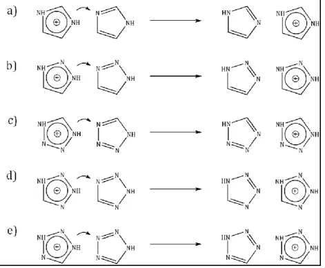
(Figure I-17). It involves two steps: i) intermolecolar proton transfer (PT) reactions along the chain, ii) reorientation of the scaffold for restoring the starting conformation and having subsequent PT reactions. The difference between the two models concerns the PT step which takes place as a cooperative process (Figure 17, a) or by migration charged defects (Figure I-17, b). On the contrary, the reorientation step in both models involves a cooperative rotation of all the imidazoles in the hydrogen-bonded chain. This second step is expected being the rate limiting step since it involves the breaking of strong hydrogen bonds.107,110
Even though imidazole and imidazole-like compounds can offer the opportunity of having PEMs working at high temperatures and low humidity conditions avoiding water dependent conductivity, they have a major drawback. Indeed, being small molecules, they can leach out gradually during the process leading to a long-term decline in the performance of PEMFCs.112 The most efficient approach for solving this leaching issue consist of incorporating
CHAPTER I: Background and objectives
24
bonded, the azoles cannot been dragged out of the membrane while their local mobility is retained. In other words, instead of using them as alternative liquid solvents, these heterocycles became part of new alternative membranes, namely azole-based polymers.
Figure I-17: Proton conduction mechanism in imidazole proposed b a) Daycock110 and b) Kawada111
(adapted from107).
Azole-based polymers as anhydrous proton conductors
The poly(benzimidazole) (PBI) (figure I-18) is considered the precursor of the azole-based polymers electrolytes. In 2000 Kawanara et al.113 shown that PBI films and strong acid
(phosforic and solforic acid) form polymer complexes thermally stable up to 500°C and able to reach high conductivity in anhydrous conditions (10-5 S/cm at 160°C). The formation of the
polymeric complex was explained as the result of acid-base interactions between imidazole moieties of PBI and acid molecules whereas the proton conduction as the result of Grotthuss mechanism involving the acid ( i.e. exchange of protons between H3PO4 and H2PO4-).
25
One year later Schuster et al114 laid the foundations of the basic concept according to
which the immobilized azole moieties can directly participate in the proton conduction mechanism. Indeed, a series of compounds with imidazole tethered to the chain ends of oligo(ethylene oxide)s (named Imi-nEO, figure I-19) reached high conductivity at 120 °C in anhydrous conditions.
Figure I-19: Structure of the Imi-nEO (n=2,3,5) compounds investigated by Schuster and al.114
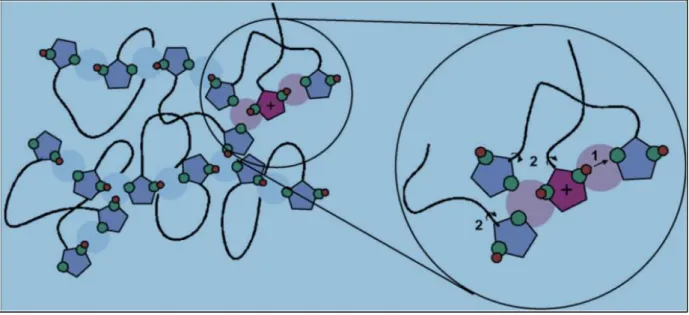
Since the vehicle mechanism cannot take place after heterocycles immobilization, the authors also suggested that the proton conductivity of these systems should be the result of a concerted (Grotthuss) proton transport in which a rapid long range transport of the "excess" protons occurs involving PT reactions between protonated imidazoles and their neutral neighbors followed by a conformational reorganization through rings rotation (figure I-20). Although these systems are much smaller than a fully polymeric system, their successful synthesis and characterization as well as their high conductivity demonstrated that the idea of reach high proton mobility in condensate phase through a fast N-heterocycle mediated proton trasport was a viable strategy. Based on these evidences, several azole-based proton conducting polymers have been synthesized in the last few years109,115-120 Among them, systems having a
backbone structure of polyethylene (table I-2) have been extensively studied both as pure polymers or as blends with strong acids such as H3PO4 or H2SO4. Notably, concerning the acid
blending, two different strategies can be envisaged:
- doping with small amount of acid ( < 15 mol % with respect to the azole units) - blending with molar excess of acid
In the first case the increasing of the acid content plasticizes the materials shifting the temperature of glass transition (Tg) to lower values. The resulting higher polymer backbone mobility is consider the reason of the increased proton conductivity with respect to the pure polymer. On the contrary, it is commonly accepted that in systems where a molar excess of acid is used, the conductivity of the blends is mainly based on proton transfer between acid moieties as well as on their self diffusion.