HAL Id: hal-01385743
https://hal.archives-ouvertes.fr/hal-01385743
Submitted on 22 Oct 2016HAL is a multi-disciplinary open access archive for the deposit and dissemination of sci-entific research documents, whether they are pub-lished or not. The documents may come from teaching and research institutions in France or abroad, or from public or private research centers.
L’archive ouverte pluridisciplinaire HAL, est destinée au dépôt et à la diffusion de documents scientifiques de niveau recherche, publiés ou non, émanant des établissements d’enseignement et de recherche français ou étrangers, des laboratoires publics ou privés.
Distributed under a Creative Commons Attribution| 4.0 International License
Modeling and Numerical Computation of Necking in
Round Bars Using a Total Lagrangian Elastoplastic
Formulation
Anh Le Van, Philippe Le Grognec
To cite this version:
Anh Le Van, Philippe Le Grognec. Modeling and Numerical Computation of Necking in Round Bars Using a Total Lagrangian Elastoplastic Formulation. Computer Modeling in Engineering and Sciences, Tech Science Press, 2001, 2 (1), pp.63-72. �10.3970/cmes.2001.002.063�. �hal-01385743�
Modeling and Numerical Computation of Necking in Round Bars Using a Total
Lagrangian Elastoplastic Formulation
A. Le van1, P. Le Grognec1
Abstract: Necking is a bifurcation phenomenon ob-served in round bars under tensile loading and has been investigated in numbers of papers. In the present work, it is modeled within the framework of finite rate-independent plasticity. The theory is based on thermody-namic foundations developed for standard materials and results in a total Lagrangian formulation for finite plas-ticity, where the total strain is decomposed additively ac-cording to [Green and Nagdhi 1965)] and the hardening is characterized by a nonlinear isotropic hardening law of the saturation type.
The discretization and consistent linearization of the elastic-plastic equation set using the standard finite el-ement procedure lead to a low-cost algorithm, robust enough to deal with necking problems.
The numerical computations of necking are performed on cylindrical bars with various boundary condition types and the corresponding results compared with those ob-tained in the literature.
keyword: elastoplasticity, necking bifurcation, total
Lagrangian formulation, finite element analysis
1 Introduction
Necking is an bifurcation phenomenon observed in cir-cular cylindrical bars under tensile loading and has been investigated in numbers of works for its theoretical mod-eling and numerical computation. The pioneering pa-pers dated back to the 70's and were due to [Needleman (1972)], [Argyris and Doltsinis (1979)]. A lot of signif-icant results were obtained in these works, although the computed necked configurations did not resemble exper-imental observations. Later, [Besdo (1987)] was among the first to give a realistic necking shape. More recently, studies using other formulations have been developed
1
Laboratoire de Mecanique et Materiaux, Division Mecanique des Structures, Ecole Centrale de Nantes. 1, rue de Ia Noe, BP 92101 -44321 Nantes cedex 3, France
by [Simo (1988)], [Simo (1992)], [Simo and Hughes (1998)] and [Brtinig (1998)], providing further results on necking. The numerical solution by Simo necessitates mixed finite elements, moreover the line search method is used to get across the limit point.
Whereas most papers considered a cylindrical circular bar with both ends assumed to be shear free, [Needle-man (1972)] dealt with two types of boundary conditions, shear free ends and cemented to rigid grips ones. [Brtinig (1998)] went further by also considering the whole ten-sile specimen with shear free stiff heads and then com-pared the results corresponding to the three cases. Most of the previous investigations were performed within the framework of finite rate-independent plastic-ity, assuming a yield criterion in the stress space and an isotropic hardening. Outside this context, analyses using the strain space representation of the finite plasticity were proposed by [Besdo (1987)] and [Simo (1988)]. Other nontraditional approaches can be used to successfully solve the necking problem, as shown by [Atluri and Mu-rakawa (1980)], using a modified complementary energy principle instead of the conventional principle of virtual work. Also, the integral equation method was shown to be capable of solving bifurcation and post-bifurcation problems, see [Okada, Rajiyah and Atluri (1990)]. On the other hand, thermal aspects in necking were taken into account by [Kleiber (1992)] who presented a simple solution scheme for elastoplasticity as well as thermoe-lastoplasticity. Also, one can use none of finite plasticity but a viscoplastic type constitutive law in small strains in order to describe necking behavior in viscoplasticity, e.g. see [Rappaz, Bellet and Deville (1998)].
In the present work, necking is studied within the frame-work of finite rate-independent plasticity. The theory . is based on thermodynamic foundations established for generalized standard materials [Halphen and Nguyen (1975)], [Germain, Nguyen and Suquet (1983)] andre-sults in a total Lagrangian formulation for finite
plas-ticity. The total strain is decomposed additively accord-ing to [Green and Naghdi (1965)]. The yield function is of von Mises type and depends on the symmetric Fiola-Kirchhoff stress tensor. The hardening in the material is characterized by a nonlinear isotropic hardening law of the saturation type, as in [Simo (1988), Part II] and [Simo (1992)]. However, here it relates Lagrangian (material) variables, namely the Lagrangian hardening variable and the Lagrangian effective plastic strain.
The numerical implementation using standard finite el-ement analysis is simple and yet robust enough to ac-curately reproduce the necking phenomenon. The local integration of the elastic-plastic equation set is carried out using the fully implicit integration scheme (backward Euler difference scheme), which ensures both the stabil-ity and the symmetry of the consistent tangent modulus. The numerical computations of necking are carried out both on shear free end bars including an initial small geometrical defect and geometrically perfect bars with gripped ends. The corresponding results are then dis-cussed in some detail and compared with those obtained in the literature.
2 Theoretical background
symmetric too, see [Green and Naghdi (1965)], [Casey and Naghdi (1980)].
In a quasi-static process, the equilibrium equation reads
(3)
where
F
is the deformation gradient,I:
the second Fiola-Kirchhoff stress tensor (symmetric),Po
the reference mass density andf
0the body force. The product II=is the first Piola-Kirchhoff stress tensor, it is not
symmet-- symmet-- T
ric whereas
II.F
is.The total Lagrangian formulation presented herein is based on thermodynamic foundations developed for the so-called generalized standard materials [Halphen and Nguyen (1975)], [Germain, Nguyen and Suquet(1983)]. Within this framework, we consider that the state of any particle and at any time is characterized by the following state variables : the total strain
E,
fue plastic strainEP
and another internal variable to account for the deforma-tion history, represented by the scalar hardening variable denoted by a.To complete the equation set for the time-independent elastic-plastic problem, we shall provide the state laws together with the ~volution laws. The state laws give the symmetric stress
'f:
and the thermodynamic conjugate A, dual of the hardening variable a, by differentiating the free energy per unit volume wLet us consider a three-dimensional continuum body which at initial time t0 occupies a region
no
bounded bysurface S0 and assume that the body undergoes a
quasi-static elastic-plastic transformation. The initial config-uration
no
will be chosen as the reference one and ther;
equations of the problem expressed using Lagrangian variables relative to this configuration.aw
A =-aa
(4)
As usual, the stored-energy w is assumed to be the sum of the elastic energy we -function of the elastic strain
The motion of the body in the Lagrangian description is defined by the displacement field denoted by
U.
The deformation inside the body is measured by the Green strain tensor defined in terms of the displacementAccording to [Green and Naghdi (1965)], [Green A. E.; Naghdi P.M. (1971)], the strain tensor E is decomposed additively as
where the so-called plastic strain
EP
is assumed to be=e
symmetric and objective, so that the elastic strain E is
=e
E only - and the hardening energy wa - function of the hardening variable
a
(5)
For metals, we can assume small elastic strains and choose the elastic energy as a quadratic function of the elastic strain
(6)
where
f>
= 211i+
AJ
denotes the isotropic elasticity tensor(i
is the fourth-order identity tensor,l
=ei
0e
j 0e
j 0ei '
describe nonlinear hardening effects, the hardening en-ergy is chosen as a function containing exponential terms
1 2 (
exp(-c3a))
wa.(a)
=coa+
2
cza
+(ct-co) a+
c
3
(7)
where the coefficients ci are material-dependant con-stants.
The state laws then yield the stress-strain relation and the nonlinear relation between hardening variables
3 Numerical implementation
In order to numerically solve the above stated elastoplas-tic problem in the context of the finite element method, it is more convenient to replace the equilibrium equation (3) by the virtual power principle
\fU*
'
=T :=__,. _, _,.
fn.o
TI : gradV*dQo-fn.o f
0V*dQo- fso
U*
.TI.NdS0 = 0(12)
(Sa) The nominal stress vector
T
=
TI.Nrelated to the refer-ence normal Nis known on the part of boundary where(Sb) dead loads are prescribed. The elastic and plastic ranges at any particle in the body
are defined by the yield function f _?f von Mises type, depending on the symmetric stress
I:
and the hardening variable A(9)
where Sis the deviator of stress
I:
and 0'0 the initial yieldstress.
The evolution laws result from the generalized maximum plastic dissipation rule and provide the plastic strain and hardening variable rates by differentiating the yield func-tion with respect to its variables
~p=
af
-a=}..!
(10)where the
pl~tic
multiplier }.. satisfies }.. ;:::: 0 if f(I:,A) = 0 and :I:
2::
0, otherwise ~0. Of course, there is no relation between the Lame constantA
and the plastic multiplier }... Relation (1 Oa) is the plastic flow rule and relation (lOb) the hardening law. They identically fulfill the second law of thermodynamics for continua, written in terms of objective Lagrangian quantities.Since the plastic strain is a Lagrangian variable, its rate is obtained by ordinary differentiation with respect to kinematic time t. There follows from relations (9)-(10) that the hardening rate is equal to the Lagrangian
equivalent plastic strain rate
· Jz=P =P
a=P= 3 E :E (11)
Relations (1)-(3), (8)-(10) form a coupled system of 30 scalar partial differential equations with 30 scalar un-knowns
U,
Ee, EP,
I:, A,a,
andi.
The discrete formulation is obtained using the
follow-~g vector and matrix notations. A second-order tensor
T
(symmetric or not) is represented by a column vector {T} of nine components as follows{Tf {Tt, Tz, T3, T4, Ts, T6, T7, Ts, T9}r
= {Tu, Tzt, T31, T12, Tzz, T3z, T13, Tz3, T33}r (13) Thus, the ~omponents of vector {T} are related to those of tensor
T
by {T}k=
T pr H k=3(r-1 )+p. It should be noted that second order tensors are represented by vec-tors with nine components instead of six as usually done. In fact, this representation mode, which is necessary for unsymmetric matrices such as the displacement gradientH or the stress TI, does not entail extra computational cost, as we shall see below. Similarly, in matrix notation, a fourth-order tensor Tis represented by a (9x9) matrix [T] as follows TttuTtttzTtll3T !121Ttt22T uz3Tll3tTtl32Tll33 TztuTzuzTzu3 1r3tttT3ttzT3tt3 T1211 [T] = Tzm T3211 Tt311 T2311 T3311 (14)
Explicitly, the components of matrix [1r] are related to those of tensor T by Tkt=Tprqs H k=3(r-l)+p, £=3(s-l)+q.
Within an element with nne nodes (nne = node number of the element), the displacement gradient H
=
gradUisapproximated by
{H} =
[G]{UY (15)In the above relation, vector
{H}
has 9 components, {UYis the vector of element nodal displacements with 3nne components, matrix [G] is of dimension (9x3nne) and defined bywhere Ni are the usual shape functions and l3 denotes the unit matrix of the 3rd order.
Note that matrix [G] does not depend on the nodal dis-placements. Moreover, it has the advantage of being sparse and regularly populated. This allows us to com-pute the internal force vector as well as the tangent matrix in a simple and efficient way, as shown in proposition 2 below.
The discretization and consistent linearization of the elastic-plastic equation set lead to a nonlinear matrix sys-tem which can be solved by a incremental procedure. The convergence at every time step requires a Newton type iterative scheme. Within each iteration, the local integration of the elastoplastic equations ~et (8)-(1 0) is carried out in order to compute the stress II and the con-sistent tangent ten~or arr;a'F corresponding to a given strain increment L\E. Then we can build up the element internal force vector and the element tangent matrix de-fined as
{'PY =
1raY
{IT}dno
(17)[Kr
=
~~~F
=
1
raYr~~][G]dno
(18)The local integration procedure is formally the same as in small strains, the rate equations are discretized us-ing the fully implicit integration scheme (backward Euler scheme) and we get the correction for the plastic multi-plier at the k-th local iteration [Simo and Taylor (1985)]
(3
=Ell
y
2 S - O'o -An-Io/Jk)
=
-L\/Jk-1)+
(19)3p+h
=E
where h=a2wa/aa2, J1 is the shear modulus, S the devia-tor of the elastic trial stress,
=f
=
2p ( dev(E) -E:_
1) •The subscript (n-1) denotes known quantities at the pre-vious time step. The plastic multiplier increment
L\A.
ob-tained at convergence allows us to ~p~ate the unsymmet-ric stress II by using relation II F.E and=E
E
="!-
21l{z"x
~~~~~
+
~
(3A+ 2p)
(trE)
l
(20)On the other hand, the solution convergence at each iter-ation requires computing the consistent tangent modulus ai:;a:E
Eventually, the consistent tangent tensor arrjaF entering in the construction of global stru~ur~ tangent matrix is derived from the above tensor ai:;a:E by means of the following proposition.
Proposition 1
By using an appropriate change of variables, the follow-ing symmetry cond~on ~an always be satisfied for the expression of stress E:
VT
(not necessarily symmetric),E (T,
state attn-t)
=E
(TT
,state attn-1)
(22)Then one has
an
a'F (
-=)T =a'!: =T
LE +F.aE.F (23)
It can be shown that the above discretization pro-cedure leads to existence of a discrete potential w(F, stateattn-t}_su:_hthatiTT =aw(F) jaF. We de-duce that tensor arr;a'F possesses themirror symmetry:
( arr;a'F) = (arr;a'F) and that its matrix
represen-ijkl lkji
tation [aiijaF] is symmetric. From (18) there follows the symmetry of the tangent consistent modulus.
To end this section, let us note that one can take advan-tage of the sparse and regular nature of matrix [G], Rela-tion (16), in order to prove the following proposiRela-tion and
remarkably reduce the operation number for the compu-tation of the element internal force vector
{'PY
and the element tangent stiffness matrix [KY , Relations ( 17) and (18). Proposition 2 Vi,jE{1, ... ,3nne}, (24) e1
arrpr
K..=
Na r - - N b sdQo IJ e •aF
qs·
(25)where implicit summations are made over r, sE{1,2,3}, whereas integers a, bE{l, ... ,3nne}, and p, qE{l,2,3}are expressed in terms of integers i, j by
a=Int(i~2), b=Int(jj2), p=i-3(a-1), q=j-3(b-l)
(Int=lnteger part of)
Relations (24) and (25) show that computing the element internal force vector and the element tangent stiffness matrix is not so tremendous a task.
4 Numerical results
4.1 Geometry and boundary conditions
The numerical computations are performed on a circular cylindrical bar of initial length 2£0=48mm and of initial radius ro=4mm.
Concerning the boundary conditions, the bar is modeled in two ways:
{i) The first one is most commonly adopted in the liter-ature. During the loading process, the ends of the bar remain shear free so that the radial displacement thereat is not prevented. To trigger the initiation of necking, an axisymmetric geometric imperfection is introduced in shape of a full cosine wave with an amplitude of 1% of the initial radius.
(ii) Another way to compute the necking behavior is to consider a geometrically perfect bar with its ends ce-mented to rigid grips, as in [Needleman (1972)] and [Brtinig (1998)]. Note that in this case there is no need of a geometrical defect for the onset of necking.
4.2 Material properties
The Young modulus is E=2.1011Pa, the Poisson ratio v=0.3 and the initial yield stress cr0=400MPa. The co-efficients of the hardening law (8b) are so adjusted that
a. Meshno. 1 b. Mesh no. 2 ( 4 x 125 elements) ( 4 x 400 elements) Figure 1 : Perfect bar with gripped ends. Initial and final meshes.
the numerically derived load-displacement curve best ap-proximates the experimental curve of a given standard steel (XC48C) : co=O (no initial hardening), c1 =220MPa,
c2=-560MPa and c3=15.
4.3 Meshes
Because of obvious symmetry, we only have to con-sider one quarter of the specimen the length of which is fo=24mm. For each boundary condition type, the numer-ical computations are carried out using two axisymmetric meshes (Figure 1) :
(i) A coarse mesh with 125 axisymmetric eight-node quadrilaterals.
(ii) In order to check the sensitivity of the numerical results to mesh refinement, another computation is per-formed over a finer mesh with 400 elements, figure lb.
4.4 Numerical results in the case of the shear free end bar with imperfection
The bar is subjected to axial end displacements corre-sponding to a maximum relative elongation of 23% at-tained after 25 time steps and Figure 1 shows the uncle-formed and final configurations.
With the 125- and 400-element meshes, on average 4 it-erations are necessary to satisfy the convergence toler-ance of l.e-6, with a peak of 8 iterations just after going through the limit point on the load-displacement curve
1.6 --~-free end perfect bar_
gripped end perfect bar-+--~
I
free end imperfect bar
0.21---t
0.05 O.i 0.15 0.2
uB/Io
Figure 2 : Load-displacement curves
shown in Figure 2. As a matter of fact, the plots corre-sponding to the coarse and the finer meshes are found to be indistinguishable, thus validating the insensitivity of the numerical results to mesh refinement.
The load-displacement curve representing the tensile load F versus the axial end displacements U B is shown
in Figure 2. The tensile load, after reaching its maximum value equal to 1.48 times the elastic yield force, decreases when the necking takes place. For a relative elongation of 23%, it falls down to 76% of its maximum value. For comparison, we also perform the computations over a perfectly cylindrical bar. As expected, this bar remains cylindrical during the whole deformation process and the necking never takes place. The corresponding ten-sile force plotted in Figure 2 attains its maximum value later than the imperfect bar and very slightly decreases afterwards. We also find that bifurcation occurs about the maximum load point, as in [Needleman (1972)] and [Briinig (1998)], although the precise location of bifur-cation point is not known. It is noteworthy that the max-imum load point (1.48 times the elastic yield force) and the bifurcation point (engineering strain of 16% approx-imately) are very close to those obtained by [Okada, Ra-jiyah and Atluri (1990)] for the necking of a tensile plate in plane strain.
Now let us look at the change in the radius of the central cross-section of the bar which is an essential indicator of the necking behavior. At the beginning, the deformation
free end perfect bar
0.05 0.1 0.15 0.2
uB/Io
Figure 3 : Necking radius vs. axial elongation
is almost homogeneous and the bar remains cylindrical. However, beyond a certain elongation the radial displace-ment becomes suddenly more pronounced in the central region of the bar, and eventually the high concentration of strain there leads to necking phenomena.
The curve in Figure
3
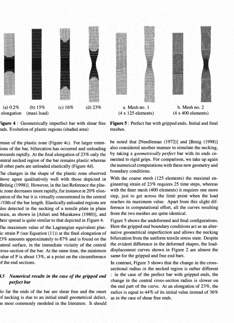
giving the central cross-section ra-dius versus elongation is tangent as expected to that of the geometrically perfect bar, which is virtually a straight line.Beyond an engineering axial strain of 15% the former rapidly deviates from the latter, and at an elongation of 23% the current radius drops to about 36% of its initial value. This behaviour is very close to the numerical and experimental results depicted by [Simo (1988)] although the material considered and particularly the formulations adopted in the previous reference and the present work are quite different. The curve shown in Figure 3 can also be compared with that computed by [Briinig (1998)], yet noting that the last Reference gives the change in cross-section area instead of the change in cross-cross-section radius. Figure 4 shows the evolution of the plastic region at dif-ferent deformation stages of the imperfect shear free end bar. The plastic deformation begins in the central region when the axial elongation UB/£0 is equal to ojE=0.2%
(Figure 4a), and it rapidly sweeps through the whole bar afterwards. Up to an elongation of 15% - i.e. until the maximum load level (see Figure 1) the bar still remains entirely plastic (Figure 4b). Yet immediately after- at 16% elongation - there suddenly occurs a remarkable
de-(a) 0.2% (b) 15% (c) 16% (d) 23% elongation (maxi load)
a. Mesh no. 1 (4 x 125 elements)
b. Mesh no. 2 (4 x 400 elements)
Figure 4 : Geometrically imperfect bar with shear free Figure 5 : Perfect bar with gripped ends. Initial and final ends. Evolution of plastic regions (shaded area) meshes.
crease of the plastic zone (Figure 4c ). For larger exten-sions of the bar, bifurcation has occurred and unloading proceeds rapidly. At the final elongation of23% only the central necked region of the bar remains plastic whereas all other parts are unloaded elastically (Figure 4d). The changes in the shape of the plastic zone observed above agree qualitatively well with those depicted in [Briinig (1998)]. However, in the last Reference the plas-tic zone decreases more rapidly, for instance at 20% elon-gation of the bar it is virtually concentrated in the central 1/1 Oth of the bar length. Elastically unloaded regions are also detected in the necking of a tensile plate in plane strain, as shown in [Atluri and Murakawa (1980)], and their spread is quite similar to that depicted in Figure 4. The maximum value of the Lagrangian equivalent plas-tic strain P (see Equation (11)) at the final elongation of 23% amounts approximately to 87% and is found on the lateral surface, in the immediate vicinity of the central cross-section of the bar. At the same time, the minimum value of Pis about 13%, at a point on the circumference of the end sections.
4.5 Numerical results in the case of the gripped end
perfect bar
So far the ends of the bar are shear free and the onset of necking is due to an initial small geometrical defect, as most commonly modeled in the literature. It should
be noted that [Needleman (1972)] and [Bmig (1998)] also considered another manner to simulate the necking, by taking a geometrically perfect bar with its ends ce-mented to rigid grips. For comparison, we take up again the numerical computations with these new geometry and boundary conditions.
With the coarse mesh (125 elements) the maximal en-gineering strain of 23% requires 25 time steps, whereas with the finer mesh (400 elements) it requires one more step, just to get across the limit point when the load reaches its maximum value. Apart from this slight dif-ference in computational effort, all the curves resulting from the two meshes are quite identical.
Figure 5 shows the undeformed and final configurations. Here the gripped end boundary conditions act as an alter-native geometrical imperfection and allows the necking bifurcation from the uniform tensile stress state. Despite the evident difference in the deformed shapes, the load-displacement curves shown in Figure 2 are almost the same for the gripped and free end bars.
In contrast, Figure 3 shows that the change in the cross-sectional radius in the necked region is rather different : in the case of the perfect bar with gripped ends, the change in the central cross-section radius is slower on the end part of the curve. At an elongation of 23%, the radius is equal to 44% of its initial value instead of 36% as in the case of shear free ends.
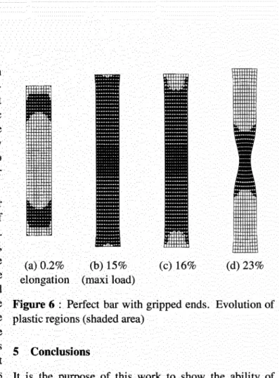
The necking radius curves in Figure 3 are different from those given in [Needleman (1972)]. However, they com-pare very well with those in [Brilnig (1998)]. Note that in the last Reference another geometry - more realistic - was also studied, which is a whole cylindrical tensile specimen with two shear free thick ends. This geometry is not considered in the present work, but according to [Brilnig (1998)] the results of the griped end perfect bar must be identical to those of the whole specimen. Figure 6 shows that the evolution of the plastic zones for the gripped end perfect bar differs notably from that of the shear free imperfect bar, especially at the beginning. When the axial elongation DB/fo is equal to croiE=0.2%, there exist separate plastic zones of different sizes in the gripped end bar. The small plastic zones, hardly visible in Figure 6a, are situated on the end cross-sections and near the lateral surface. The much larger plastic zones lie around the axis, between the central cross-section and the ends of the bar. As the overall extension increases, these plastic zones grow up together and eventually becomes connected. When the maximum load is reached - i.e. at about 15% elongation (see Figure 1) - the entire bar is plastically loaded, except for two small regions near the ends that will remain elastic throughout the whole range of straining (Figure 6b ). Just after, with a 1% additional elongation only, unloading takes place and then regularly spreads out (Figure 6c). At the final elongation of 23%, the plastic zone is reduced to the central region of the bar, over a volume slightly smaller than that of the shear free end imperfect bar (Figure 6d).
The development of plastic zones shown above is very close to that described in [Needleman (1972)]. In partic-ular, as in the quoted Reference, we also observe separate plastic zones which become connected, and the existence of small regions near the ends which remain continuously elastic. In the case of the gripped end perfect bar consid-ered here, less details are given in [Brilnig ( 1998)] for the beginning of the plastic zones evolution, however for the final stage all the results are again in quite good compar-ison.
The maximum value of the Lagrangian equivalent plas-tic strain P at the final elongation of 23% amounts ap-proximately to 83% and is found on the lateral surface, a little bit farther from the central cross-section of the bar than in the case of the shear free end imperfect bar. Of course, the equivalent plastic strain P remains zero at the few points near the ends that remain elastic throughout.
(a) 0.2% (b) 15% (c) 16% (d) 23% elongation (maxi load)
Figure 6 : Perfect bar with gripped ends. Evolution of plastic regions (shaded area)
5 Conclusions
It is the purpose of this work to show the ability of the proposed formulation of finite elastoplasticity to deal with necking bifurcation problems. Below are summa-rized the main features of the theoretical and numerical formulations. Besides, further comments are also added on the results obtained in the preceding sections.
(i) The proposed theory is based on thermodynamic foun-dations established for generalized standard materials and results in a total Lagrangian formulation for finite plasticity. Since all relations are expressed in terms of Lagrangian variables, the material frame indifference is automatically satisfied within this formulation. The de-formation history in the material has been characterized by a nonlinear relation of the saturation type between the isotropic hardening variable and its conjugate, Equation
(8b).
(ii) The numerical implementation using standard finite element analysis is simple and yet robust enough to ac-curately reproduce the necking phe~omenon. Written in terms of the Green strain tensor
E
and the symmet-ric Piola-Kirchhoff stress tensor 1:, the local integration procedure is formally the same as in small strains. The rate equations are discretized using the fully implicit inte-gration scheme (backward Euler scheme), which ensures both the stability and the symmetry of the consistent tan-gent modulus. In computing the global tantan-gent matrix,the update of matrix [di1/dF] is made by means of Rela-tions (21) and (23).
On the other hand, Relations (24) and (25) show that computing the element internal force vector and the el-ement tangent stiffness matrix is not a highly time-consuming operation.
(iii) The numerical computations of necking are carried out both on imperfect bars with shear free ends and geo-metrically perfect bars with rigid gripped ends.
For each boundary condition type, the numerical compu-tations carried out using a coarse and a finer meshes are found to yield indistinguishable results with the same rate of solution convergence, thus validating the insensitivity of the numerical results to mesh refinement.
The robustness of the implemented solution procedure is successfully assessed since 23% elongation can be at-tained in only 25 time steps, giving sensible necking sim-ulation of the tensile bar.
All the obtained results have been quantitatively and qualitatively analyzed in some detail. Comparisons are also made with other formulations in the literature, show-ing agreements or differences in the load-displacement relationship, the necking radius versus axial elongation, and the evolution of plastic zones during the straining history.
(iv) It should be noticed that necking is usually referred to as a bifurcation phenomenon in the literature, whereas a true bifurcation computation of bar necking- as done in [Needleman (1972)] - is rare. [Needleman (1972)] con-sidered a geometrically perfect bar with shear free ends and performed a real bifurcation analysis by discretiz-ing a variational principle of Hill with the finite element method. As commonly done in other works, here we have solved the necking as a standard deformation prob-lem by either introducing an initial imperfection of 1% in the radius or preventing the radial end displacement.
In connection with bifurcation aspects, let us note an in-teresting issue not often considered, which concerns the sensitivity to geometric or material parameters. In the present work, the numerical computations have been car-ried out with a unique set of bar dimensions and material values. The sensitivity study requires more extended dis-cussions and is beyond the scope of this work.
(v) The computer program used here can be improved with path-following techniques such as arc-length and branch-switching methods, in order to deal with more
general problems in finite displacements and plastic strains, including limit point instabilities and bifurcation points. First results due to these enhancements have been obtained for the pinched cylinder modeled with shell ele-ments in finite plasticity [Le Grognec and Levan (2000)]. Further investigations to treat static plastic buckling of shell-type structures are being developed.
References
Argyris
J.
H.; DoltsinisJ.
St. (1979) : On the large strain inelastic analysis in natural formulation. Part I : quasistatic problems, Comp. Meth. Appl. Mech. Eng., 20, pp. 213-251.Atluri S. N.; Murakawa H. (1980): New general and complementary energy theorems, finite strain, rate sensi-tive inelasticity and finite elements : some computational studies, pp. 28-48, in Nonlinear Finite Element Analysis in Structural Mechanics. Proceedings of the Europe-US Workshop, ed. by W. Wunderlich et al, July 38-31, 1980, Ruhr-Universitat Bochum, Germany.
Besdo D. (1987) : Total Lagrangian strain-space-representation of the elasto-plasticity of metals, pp. 1357-1364, in Proceedings of the 2nd Int. Conf. on
Con-stitutive Laws for Eng. Materials : Theory and Applica-tions, vol. II, ed. by C.S. Desai et al, January 5-8, 1987, Tucson, Arizona, USA.
Briinig M. (1998) : Numerical analysis and modeling of large deformation and necking behavior of tensile spec-imens, Finite Elements in Analysis and Design, 28, pp. 303-319.
Casey
J.,
NaghdiP.
M. (1980) : A remark on the use of the decomposition F=FFP in plasticity, J. Appl. Mech., 47, pp. 672-675.Germain P.; Nguyen Q. S., Suquet P. (1983) : Con-tinuum thermodynamics. J. Appl. Mech., 50, pp. 1010-1020.
Green A. E.; Naghdi P. M. (1965) : A general theory of an elastic-plastic continuum", Archive for Rational Me-chanics and Analysis, 18, pp. 251-281.
Green A. E.; Naghdi P.M. (1971): Some remarks on elastic-plastic deformation at finite strain. Int. J. Engng. Sci., 9, pp. 1219-1229.
Halphen B.; Nguyen Q. S. (1975) : Sur les materiaux
standard generalises, J. de Mecanique, 14, 1, pp. 39-63. Kleiber M. (1992) : On solving problems of advanced
plastic flow, pp. 349-361, in Finite Inelastic Deforma-tions - Theory and AppicaDeforma-tions, IUTAM Symposium
Hannover/Germany 1991, D. Besdo, E. Stein (Eds.), Springer Verlag.
Le Grognec P.; Le van A. (2000) : Buckling and
post-buckling of thin elastoplastic cylindrical shells with finite rotations. 2000 ASME International Mechanical Engi-neering Congress, November 5-10, 2000, Orlando, USA.
Needleman A. ( 1972) : A numerical study of necking in
circular cylindrical bars, J. Mech. Phys. Solids, 20, pp.
111-127.
Okada H.; Rajiyah H., Atluri S. N. (1990) : A full
tangent stiffness field-boundary-element formulation for geometric and material non-linear problems of solid me-chanics, Int. J. Num. Meth. Eng., 29, pp. 15-35.
Rappaz M.; Bellet M.; Deville M. (1998): Modlisation Numrique en Science et Gnie des Matriaux. Volume 10
of the collection "Trait des Matriaux". Presses Polytech-niques et Universitaires Romandes.
Simo
J,
C. (1988) : A framework for finite strainelasto-plasticity based on maximum plastic dissipation and the multiplicative decomposition. Part I : Continuum for-mulation, Comp. Meth. Appl. Mech. Eng., 66, pp.
199-219; Part II: Computational aspects, Comp. Meth. Appl. Mech. Eng., 68, pp. 1-31.
Simo
J,
C. (1992) : Algorithms for static and dynamicmultiplicative plasticity that preserve the classical re-turn mapping schemes of the infinitesimal theory, Comp. Meth. Appl. Mech. & Engng., 99,61-112.
Simo
J.
C.; Hughes T. H. R. (1998) : Computational Inelasticity, Springer.Simo
J.
C.; Taylor R. L. (1985) : Consistent tangentoperator for rate-independent plasticity. Comp. Meth. in Appl. Mech. & Engng, 48, pp. 101-118.