affiliée à l’Université de Montréal
Flow Control and MRI-Compatible Particle Injector: Application to
Magnetic Resonance Navigation
NING LI
Institut de génie biomédical
Thèse présentée en vue de l’obtention du diplôme de Philosophiæ Doctor
Génie biomédical Avril 2019
affiliée à l’Université de Montréal
Cette thèse intitulée :
Flow Control and MRI-Compatible Particle Injector: Application to
Magnetic Resonance Navigation
présentée par Ning LI
en vue de l’obtention du diplôme de Philosophiæ Doctor
a été dûment acceptée par le jury d’examen constitué de :
Frédéric SIROIS, président
Sylvain MARTEL, membre et directeur de recherche
Gilles SOULEZ, membre et codirecteur de recherche
Julien COHEN-ADAD, membre
DEDICATION
ACKNOWLEDGEMENT
I would like to express my special thanks and appreciations to my research supervisors, Professor Sylvain Martel and Professor Gilles Soulez. They are both tremendously honourable mentors for me. I am so grateful to Sylvain for giving me the means to do this doctorate. His energy, ideas and ambition in dealing with compelling research problems are excellent models for me to learn from. My co-director, Dr. Gilles Soulez, is someone who can not be replaced on this journey. He provided excellent guidance for this project and always gave me constructive comments concerning my work. Without their help, this project would not have seen the light of the day.
Thanks to Mr. Charles Tremblay, an energetic and joyful friend. He made the working environment interesting and efficient. He was always willing to listen and help me.
Thanks to other members of the Nanorobotics laboratory: Mahmood Mohammadi, Dumitru Loghin, Maxime Latulippe, Arash Azizi, Kévin Gagné, Yasamin Majedi, et al. Everyone is nice and patient regarding my communication problems in English.
I would also like to thank other members of our research group: Samuel Kadoury and Gerald Moran. They provided excellent guidance for this particular research topic.
Thanks to Francois Michaud. We spent a lot of time together making the setup and doing the experiments. He is also a wonderful friend and I admire his positive outlook and his dream of becoming a doctor.
Thanks to Rosalie Plantefève, she was always willing to help me and share her findings and experiences. Her rigorous academic attitudes and statistical methods gave me great inspiration.
Thanks to members in the cooperative laboratory at the University of British Columbia: Prof. Urs, Dr. Samuel and Mrs. Zeynab. We had a very pleasant cooperation experience. Thanks to their works, I was able to acquire the perfect particles used for liver embolization.
Special thanks to Yuting Jiang, a happy girl with dreams, who has helped me find spelling mistakes in each of my paper and this thesis.
I would like to thank all my friends. There are too many to list here, but I hope you know who you are!
and support from overseas. I love them so much, and I would not have made it this far without them.
In the end, I would like to express my special thanks to my beloved wife Cui Wang who was always my indispensable support for all these years. Words cannot express how grateful I am to her.
RÉSUMÉ
Notre groupe de recherche travaille sur une technique de navigation par résonance magnétique (NRM) qui vise à améliorer l’efficacité du ciblage des médicaments vers les zones tumorales. Cette technique a été subdivisée en cinq parties :
1. Conception des microparticules. La taille et les matériaux constituants les particules doivent répondre aux exigences médicales et physiologiques de l'embolisation humaine, ainsi qu'à la faisabilité du pilotage des microparticules en utilisant les gradients magnétiques (≤ 40 mT/m) d'un système clinique d'imagerie par résonance magnétique (IRM).
2. Contrôle du flot sanguin. Un contrôle du flot sanguin a été mis au point pour permettre une navigation suffisamment rapide afin de réduire le temps d'injection tout en étant suffisamment lente pour assurer un taux de réussite élevé pour la NRM.
3. Conception d’un injecteur pour la formation d'agrégats de microparticules de tailles contrôlables. Un injecteur IRM compatible a été conçu pour permettre l’injection d’agrégats de particules pour à la fois réduire le temps d'injection et augmenter l'efficacité de la NRM en raison du volume magnétique plus important injecté à chaque fois.
4. Logiciel NRM. Une séquence NRM est utilisée pour suivre et orienter les agrégats injectés.
5. Intégration de l'injecteur de particules, du contrôle du flot sanguin et du logiciel NRM.
Dans cette thèse, nous cherchons à trouver des solutions aux étapes 2, 3, 4 et 5.
L’auteur a constaté que la combinaison d’un micro-flot vibratoire et d’un flot constant à faible vitesse pouvait rendre la vitesse de dérive des particules basse et constante. Un système de contrôle de l'écoulement composé d'une machine vibratoire générant le flot en question et d'une pompe péristaltique a été conçu et fabriqué pour générer ces deux types d'écoulement. Ensuite, le système a été intégré au NRM pour tester les manipulations in vitro visées. Dans une IRM de 1.5 Tesla (T), les microparticules encapsulant des nanoparticules superparamagnétiques ont été navigués dans un canal à bifurcation unique en forme de Y. En comparant les résultats avec le NRM à débit constant, nous avons démontré que le modèle de flot vibrantoire proposé peut améliorer de manière significative le taux de réussite du NRM avec un gradient magnétique inférieur à 40 mT/m qui correspond au seuil maximum de gradient qui peut être utilisé sur une IRM clinique traditionnelle.
Par la suite, un injecteur de particules compatible avec l'IRM, composé de deux pompes péristaltiques, d'un compteur optique et d'un piège magnétique, a été proposé pour former des agrégats de particules de taille spécifique. Afin de déterminer la conception et la configuration optimales de l'injecteur, les propriétés magnétiques des microparticules, la compatibilité magnétique des différentes pièces de l'injecteur et la distribution spatiale du champ magnétique du système IRM ont été étudiées de manière exhaustive. Les particules utilisées dans l'essai avaient un diamètre de 230 ± 35 µm, ce qui respecte les spécifications requises pour une chimioembolisation trans-artérielle (TACE) chez l'adulte. Nous avons démontré que l’injecteur pouvait former des agrégats contenant 20 à 60 microparticules avec une précision de 6 particules. Les agrégats ayant des longueurs globales correspondantes de 1.6 à 3.2 mm, ce qui se situe juste dans l’échelle des diamètres internes des artères hépatiques propres et des branches de division droite et gauche. Par la suite, des agrégats constitués de 25 particules ont été injectés dans un fantôme imitant des conditions physiologiques et rhéologiques humaine. Dans ce cas, 82% des agrégats (n = 50) ont réussi à atteindre les sous-branches ciblées.
Enfin, nous avons démontré qu'il était possible d'intégrer le flot vibrant combiné avec flot constant, l'injecteur et la séquence NRM à notre injecteur afin d'établir une synchronisation entre la formation, la propulsion, la navigation et le suivi de bolus de particules dans un fantôme avec deux niveaux de bifurcation. Un modèle théorique de la taille et l'orientation des vaisseaux a été étudié et pris en compte lors du calcul de la longueur appropriée de l'agrégat de particules pour différentes tailles de vaisseaux. Une séquence d’IRM rapide (True FISP) et un gradient magnétique de 20 mT/m ont été choisis pour suivre et orienter les agrégats. Les particules magnétiques de 200 µm de diamètre moyen ont été utilisées pour évaluer l'efficacité de la NRM avec la méthode proposée. Dans les expériences, sur la base du modèle théorique, la longueur totale des agrégats a été fixée à environ 1.6 mm. Lorsqu'un agrégat était prêt, il était injecté dans le fantôme situé au centre du tunnel de l’IRM, imitant des situations réelles. Pendant ce temps, un signal de déclenchement généré automatiquement par le générateur déclenche la séquence NRM. Les agrégats de particules ont été entraînés par le flot combiné et dirigés puis suivis par la séquence NRM. En fonction de la position des agrégats dans le fantôme, la direction du gradient de navigation a été ajustée pour diriger les agrégats de microparticules dans la branche ciblée. Lorsque le tube principal du fantôme était parallèle à B0, la distribution de base des agrégats sans NRM de gauche à gauche (GG), de gauche à droite (GD), de droite à gauche (DG) et de droite à droite (DD)
était de 4%, 96%, 0% et 0% respectivement. La précision a atteint 84% (GG), 100% (GD), 84% (DG) et 96% (DD) (P < 0.001, P = 1.0, P < 0.001, 1, P <0.001) en utilisant la séquence de NRM correspondantes pour diriger chaque agrégat dans une branche ciblée. Ensuite, le fantôme a subi une rotation de 90 degrés horizontalement. Dans cette configuration, la branche D-G qui avait le plus faible ratio de distribution de base de 0%, passait à 80% (P <0.001) après NRM. De plus, le taux de réussite du MRN était toujours supérieur à 92% à la première bifurcation dans les expériences mentionnées ci-dessus.
En conclusion, ce projet a proposé un nouveau modèle d'écoulement pour augmenter le taux de réussite de la NRM avec un gradient magnétique de 40 mT/m. Il s'agit d'une étape importante pour les expériences in vivo utilisant le système d'IRM clinique. Ensuite, un injecteur compatible avec l'IRM, capable de contrôler la taille des agrégats de particules, a été conçu et testé. Enfin, la première intégration du système d’injection de particules, qui alterne un gradient de guidage et une séquence True FISP dans un logiciel NRM dédié, confirme que le NRM peut être utilisée pour naviguer in vitro des agrégats de particules à travers deux niveaux de bifurcations à l’aide d’une IRM clinique 3 T sans modification matérielle.
ABSTRACT
The author’s research group has been working on a technique of magnetic resonance navigation (MRN) which aims to improve the targeting efficiency of drugs towards tumour areas. This technique was subdivided mainly into the following steps:
1. Particle design. Sizes and materials of particles need to meet the medical and physiological requirements of human embolization, as well as the feasibility of steering the particles by using magnetic gradients (≤ 40 mT/m) of a clinical magnetic resonance imaging (MRI) system.
2. Flow control. The particles drifted by blood flow must be fast enough to decrease the particle injection time while being appropriately slow to ensure a high success rate for MRN.
3. The conception of a dedicated MR compatible injector to create microparticle aggregates with controllable sizes. The formation of aggregates can both decrease the injection time and increase the MRN efficiency because of the larger magnetic volume injected each time.
4. MRN software. An MRN sequence is used to track and steer the injected aggregates. 5. Integration of the particle injector, flow control and the MRN software.
In this thesis, I aim to find solutions for steps 2, 3, 4 and 5.
The author found that the combination of micro-vibrating flow and low-velocity constant flow could make the velocity of the drifted particles low and steady. A flow control system consisting of a vibrator and a peristaltic pump was designed and fabricated to generate these two flow patterns. Then, the system was integrated with MRN to test for the targeted in vitro manipulations. In a 1.5 Tesla (T) MRI system, microparticles encapsulating superparamagnetic nanoparticles were navigated in a Y-shaped single bifurcation channel. By comparing the results with MRN with constant flow, I demonstrated that the proposed flow pattern can significantly improve the success rate of MRN under a magnetic gradient of 40 mT/m, a force that can be obtained but is difficult to increase further when using a traditional clinical MRI system.
Subsequently, an MRI-compatible particle injector, composed of two peristaltic pumps, an optical counter and a magnetic trap was proposed to form specific-sized particle aggregates. In order to determine the optimal design and setup of the injector, the magnetic property of microparticles, the magnetic compatibility of different parts within the injector and the field
distribution of the MRI system were studied comprehensively. The particles used in the test had diameters of 230 ± 35 µm which respect the specifications needed for trans-arterial chemoembolization (TACE) in human adults. I demonstrated that the system could form aggregates containing 20 to 60 microparticles with a precision of 6 particles. The corresponding aggregate lengths ranged from 1.6 to 3.2 mm, which is just within the scale of internal diameters of the common, right and left hepatic arteries. Subsequently, aggregates consisting of 25 particles were injected into a phantom which mimics realistic physiological and rheological conditions. Under such circumstances, 82% of the aggregates (n = 50) were able to successfully reach subbranches.
At last, I demonstrated the feasibility of integrating the combined flow pattern, the injector and the MRN sequence to establish synchronization between the formation, propulsion, steering and tracking of particle boluses in a two-level bifurcation phantom. To start with the establishment of a theoretical model, the size and orientation of the vessels were comprehensively studied and took into consideration when the calculation for the appropriate length of the particle aggregate for different vessel sizes. Next, a steady-state coherent sequence (True FISP) and a 20 mT/m magnetic gradient were chosen as the MRN sequence and force used to track and steer moving aggregates. Finally, magnetic particles of 200 μm mean diameter were used to evaluate the MRN efficiency of the proposed method. In the experiments, based on the theoretical model, the aggregate length was set, through the injector, to roughly 1.2 mm. When an aggregate was ready, it was injected into the phantom located in the MRI bore, imitating real-life situations. Meanwhile, a trigger signal automatically generated by the trigger generator would start the MRN sequence. Particle aggregates were drifted by the combined flow and were steered and tracked by the MRN sequence. According to the position of the aggregates in the phantom, the direction of the steering gradient would be tuned to ensure that the particles were steered into the targeted branch. When the main tube of the phantom was parallel to B0, the left–left (L-L), left–right (L-R), right–left (R-L) and right–right (R-R) baseline distribution of aggregates with no MRN were 4%, 96%, 0% and 0% respectively. The accuracy reached 84% (L-L), 100%(L-R), 84% (R-L) and 96% (R-R) (P < 0.001, P = 1.0, P < 0.001, P < 0.001) after applying corresponding MRN operations to steer each aggregate into a targeted branch. Then, the phantom was rotated 90 degrees horizontally. In that setup, the R-L branch had the smallest baseline distribution ratio of 0%, which increased to 80% (P < 0.001)
through MRN. Moreover, the success rate of MRN was always more than 92% at the 1st bifurcation in the experiments above.
In conclusion, this project proposes a new flow pattern for increasing the MRN success rate under the magnetic gradient of 40 mT/m. This is an important step for in vivo experiments using the clinical MRI system. Then, an MRI-compatible injector, capable of controlling the size of particle aggregates, was designed and tested. At last, the first integration of the particle injection system which interleaves a steering gradient and a True FISP sequence in a dedicated MRN software confirmed that MRN can be used to navigate particle aggregates in vitro across two branch divisions in a 3 T clinical MRI system without hardware modification.
TABLE OF CONTENTS
DEDICATION ... iii
ACKNOWLEDGEMENT ... iv
RÉSUMÉ ... vi
ABSTRACT ... ix
TABLE OF CONTENTS ... xii
LIST OF TABLES ... xvi
LIST OF FIGURES ... xvii
LIST OF ABBREVIATIONS AND SYMBOLS ... xxi
LIST OF APPENDICES ... xxiii
CHAPTER 1 INTRODUCTION ... 1
1.1 Problem statement ... 1
1.2 Objectives, hypothesis and general methodology ... 3
CHAPTER 2 LITERATURE REVIEW ... 5
2.1 HCC ... 5
2.1.1 Incidence of HCC ... 5
2.1.2 Diagnosis of HCC ... 7
2.1.2.1 Measuring the liver function through blood tests ... 7
2.1.2.2 Getting the sample of liver tissues for laboratory testing (biopsy) ... 7
2.1.2.3 US ... 7
2.1.2.4 CT scans ... 8
2.1.2.5 MRI ... 8
2.1.3 Therapeutic approaches for HCC ... 9
2.1.3.2 TACE ... 10
2.2 MRI-based targeted intervention ... 13
2.2.1 MR-guided catheter navigation ... 13
2.2.2 DFN ... 16
2.3 The MRN based targeted therapeutic intervention and related researches ... 17
2.3.1 Basic concept of MRN ... 17
2.3.2 Magnetic microparticles used in MRN ... 19
2.3.2.1 Materials and sizes of MDEB ... 19
2.3.2.3 Magnetic particle aggregates in MRI ... 21
2.3.3 Magnetic gradient for MRN ... 22
2.3.4 Blood flow control during MRN ... 23
2.3.5 MR imaging and tracking technique ... 26
2.3.5.1 Basic principle of MRI ... 27
2.3.5.2 Particle imaging through spin echo (SE) sequences and gradient echo (GRE) sequences ... 28
2.3.5.3 Real-time MR imaging of magnetic particles through the steady-state coherent sequence ... 31
2.3.5.4 Flow measurement by MRI ... 32
CHAPTER 3 PROCESS FOR THE RESEARCH PROJECT AS A WHOLE AND GENERAL ORGANIZATION OF THE DOCUMENT INDICATING THE COHERENCE OF THE ARTICLES IN RELATION TO THE RESEARCH GOALS ... 34
CHAPTER 4 ARTICLE 1: COMBINING OSCILLATING FLOW AND CLINICAL MRI GRADIENTS FOR TARGETED THERAPY ... 36
4.1 Abstract ... 36
4.3 Methodology ... 38
4.3.1 Particles ... 38
4.3.2 Experimental setup and oscillating flow ... 39
4.3.3 Phenomena and principle ... 40
4.4 Results ... 42
4.5 Discussion ... 44
4.6 Conclusion ... 45
CHAPTER 5 ARTICLE 2: MRI-COMPATIBLE INJECTION SYSTEM FOR MAGNETIC MICROPARTICLE EMBOLIZATION ... 46 5.1 Abstract ... 46 5.2 Introduction ... 47 5.3 Method ... 50 5.3.1 Injector design ... 50 5.3.2 Particle design ... 54
5.3.3 Preparation of the injector for testing ... 55
5.4 Experiments and results ... 56
5.4.1 System optimization ... 56
5.4.1.1 Determination of actuator position and orientation in MRI magnetic field ... 56
5.4.1.2 Optimal flow rate for two pumps ... 59
5.4.2 Controlling particle numbers and aggregate length by using our injector ... 59
5.4.3 In-Vitro injectability and MR imaging capability tests ... 62
5.5 Discussion ... 65
CHAPTER 6 ARTICLE 3: MAGNETIC RESONCANCE NAVIGATION FOR TARGETED
EMBOLIZATION IN A TWO-LEVEL BIFURCATION PHANTOM ... 69
6.1 Abstract ... 69
6.2 Introduction ... 70
6.3 Materials and methods ... 75
6.3.1 Particle design and agglomeration with proper sizing ... 75
6.3.2 Synchronization of the MRN sequence ... 77
6.3.3 MRN sequence for particle steering and tracking ... 77
6.3.4 Experimental setup ... 79
6.4 Results ... 81
6.4.1 MDEB aggregate sizing and MDEB count ... 81
6.4.2 Determine the parameters of MRN sequence ... 82
6.4.3 In vitro MRN ... 84
6.5 Conclusion and discussion ... 87
CHAPTER 7 GENERAL DISCUSSION ... 91
7.1 Particle design ... 91
7.2 Flow control ... 93
7.3 Formation of MDEB aggregates with controllable sizes ... 93
7.4 MRN software ... 94
7.5 Integration of all parts to achieve successful MRN ... 95
CHAPTER 8 CONCLUSION AND RECOMMENDATIONS ... 97
8.1 Conclusion ... 97
8.2 Recommendations ... 98
REFERENCES ... 100
LIST OF TABLES
Table 2-1: Reproduced from [79]. Advantages and disadvantages of MR-guided catheters when
different components are used on the catheter tip. ... 15
Table 2-2: Advantages and disadvantages of different methods for blood control. ... 25
Table 6-1: Research status of the MRN in relation to this work’s aims. ... 74
Table 6-2: Imaging time required at different resolutions. ... 84
Table 6-3: Success rate of two-bifurcation MRN. ... 87
Table 7-1 Parameters of the existed particles used for MRN ... 92
LIST OF FIGURES
Figure 2-1: Reproduced from [24]. Incidence rates of HCC in different regions of the world. ... 6
Figure 2-2: Reproduced from [23]. Diagnostic algorithm and recall policy of HCC. ... 9
Figure 2-3: Reproduced from [41] and [42]. Barcelona Liver Cancer Staging system with treatment recommendations. Abbreviations: RF, radiofrequency ablation; PEI, percutaneous ethanol injection. ... 10
Figure 2-4: Reproduced from [78]. The basic principle of TACE. ... 13
Figure 2-5: Reproduced from [79]. Four different concepts of catheters that can be magnetically actuated. ... 14
Figure 2-6: Reproduced from [89]. Distribution of the magnetic gradient field around a magnetized ferromagnetic core. ... 17
Figure 2-7: Schematic diagram to show the continuous injection (a) and sequential injection (b). ... 19
Figure 2-8: Reproduced from [116]. A prototype of the injector to control and to detect the release of magnetic beads. ... 22
Figure 2-9: Reproduced from [117]. The upgraded imaging coils capable of supplying a magnetic gradient as high as 400 mT/m. Abbreviations: IGC, imaging gradient coil; SGC, steering gradient coil. ... 23
Figure 2-10: Reproduced from [120]. Schematic representation of the blood flow velocity and Reynolds number as a function of vessel size. ... 24
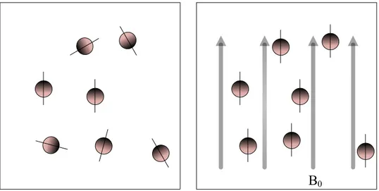
Figure 2-11: Hydrogen nuclei are randomly aligned (left). In a strong magnetic field, B0, the hydrogen nuclei precess around the direction of B0 (right). ... 27
Figure 2-12: Reproduced from [133]. SE sequence. ... 29
Figure 2-13: Reproduced from [37]. SE pulse (top) vs GRE pulse (bottom). Abbreviation: DAQ, data acquisition. ... 29
Figure 2-14: Reproduced from [134]. Typical artifacts of ferrofluid for GRE (left) and SE (right). ... 30
Figure 2-15: Reproduced from [142]. True FISP sequence diagrams. ... 32
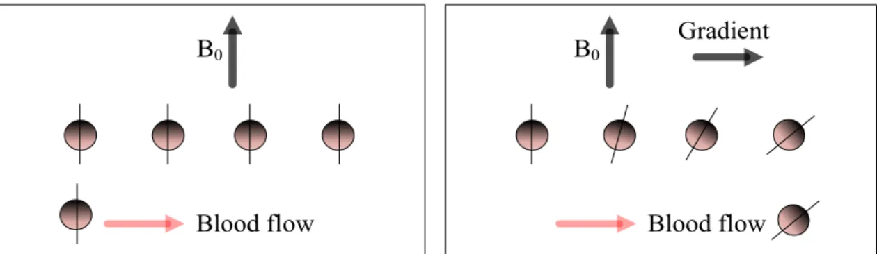
Figure 2-16: Diagrams show that a spin will acquire a phase difference when moving along the magnetic gradient. ... 33
Figure 4-1: Photo of the magnetic micro beads. ... 39
Figure 4-2: Experimental setup. (b) The pattern of an oscillating flow. ... 40
Figure 4-3: Movement of MMC aggregates drifted by a constant flow with a known velocity of 1.2 cm/s. ... 41
Figure 4-4: Sequence of images to show different positions of the MMC aggregates during the navigation using the oscillating flow and magnetic steering force. ... 43
Figure 4-5: The calculated deflection pattern of microparticles during the navigation. ... 44
Figure 5-1: Experimental setup used for particle injections. (a) Schematic diagram of the injector. (b) The counting chamber (left) and the corresponding circuit diagram (right). ... 51
Figure 5-2: Workflow of the injector and possible interface with MRI for MRN. This workflow could be adapted for DFN or selective embolization using MR-guidance. ... 53
Figure 5-3: Design and magnetic characteristics of magnetic particles. (a) Monodisperse magnetic microparticles shown in the microscope (left) are made from 60 wt.% magnetite nanoparticles (right) and 40 wt.% biodegradable polymer PLGA. (b) Magnetization curve of the microparticles. ... 54
Figure 5-4: Setup of the MRI-compatible actuator during the experiments (a) and close-up of the actuator (b). ... 55
Figure 5-5: Mapping of the gradient strength according to the position of the actuator and shape of particle aggregates according to the orientation of the tube. (a) The strength of the magnetic field and the magnetic gradient along the +Z direction (B0 direction). The iso-center of MRI bore was used as the reference zero (coordinates, 0, 0, 0). (b) Shapes of aggregates for different glass tube orientations with respect to the main field B0. ... 58
Figure 5-6: In (a), two snapshots showing a single particle (A) being injected into the counting chamber and a larger aggregate (B) being released after the resistance of the receiver reached the chosen value (Rc = 80 kΩ). The graphs show the relationship between
receiver resistance and particle number (b) and the aggregate length (c). Data are shown as the mean ± standard deviation and n experiments = 5. ... 62
Figure 5-7: Experimental setup used for injecting the formed particle aggregates into a phantom located in the MRI scanner. ... 62
Figure 5-8: The movement of a particle aggregate in the phantom into the lower left tube branch is shown in the coronal direction (a, b, c, d) optically and (e, f) by magnetic resonance imaging. Fig. 5-8 a-d show the particle aggregates before (a) and after (b, c, d) entering the phantom with the help of an MRI-compatible camera. Fig. 5-8 e and f show a coronal image of the phantom taken before (e) and after (f) an aggregate reached the branch. The dark areas and white line around the particle aggregate were caused by susceptibility artifacts [134]. Note: 1. For different particle aggregates, the probability of entering different tube branches was random because there was no magnetic navigation force. We also randomly selected one video snapshot when the angle between the main branch and B0 is 0°, 45° and 90° (see b, c, d). 2. MR correlation is only showed when the main branch and B0 are parallel because different angulation to B0 did not affect the imaging results. ... 64
Figure 6-1: Five steps of the MRN technology and the corresponding research work for each step. Step 1 shows a single DEB (diameter = 200 μm), Step 2 shows the oscillating flow pattern used in this paper, Step 3 shows the formation of a MDEB aggregate after its injection in the phantom, and Step 4 shows the MDEB aggregate position by True FISP acquisition. ... 73
Figure 6-2: A schematic diagram showing a longitudinal view, an aggregate reaching the bifurcation of the tube with (a-right) and without (a-left) magnetic gradients. The angle between the centerline of the tube and B0 is Q. In (b), we show, on an axial view, the aggregate motion along the vessel wall and the interaction between magnetic, gravitational and buoyant forces during MRN. Note that: in the calculation of Q2, we ignore the effect of the particle size. ... 76
Figure 6-3: A schematic drawing of the MRN sequence (upper) and the corresponding fluid pattern (downwards). The flow pattern ensures that the particle only moves when the gradients are operational. ... 78
Figure 6-4: (a) Glass phantom used for MRN. (b) Integration of MRN and automated injection system. ... 80
Figure 6-5: Particle number per aggregate. ... 81
Figure 6-6: The images show the movement of a single particle aggregate from the first bifurcation (A or C)to the two second bifurcations (B or D). ... 82
Figure 6-7: The MR images of an aggregate at three different resolutions. ... 83
Figure 6-8: The particle aggregates were navigated into different second tube branches when the main tube is either parallel (A-F) or perpendicular (G-L) to B0. The magnetic resonance imaging was taken from the coronal plane. Figure 6-8A-C and G–I show the particle aggregates reaching the main (A and G), first (B and H) and second (C and I) branches when carrying out R-R MRN. Figure 6-8B–E and I-L show that the particle aggregates had successfully reached four different second branches through MRN. ... 86
Figure A-1: Encapsulation system for fabricating MMCs. ... 122
Figure B-1: Photo showing a pig being transferred from the angiography room into the MRI room. ... 124
Figure B-2: CT image showing the catheter tip in the proximal hepatic artery. ... 124
Figure C-1: Setup for calculating the appropriate gradient capable of lifting microparticle aggregates. ... 129
LIST OF ABBREVIATIONS AND SYMBOLS
CT Computed tomography
DEB Drug-eluting bead
DFN Dipole field navigation
EPI Echo planar imaging FFE Fast Field Echo
FIESTA Fast Imaging Employing Steady-state Acquisition
GRE Gradient echo
HCC Hepatocellular carcinoma
L-L Left-Left
L-R Left-Right
MRI Magnetic resonance imaging
MRN Magnetic resonance navigation
Poly (lactic-coglycolic acid) PLGA
Poly (vinyl alcohol) PVA
RF Radio-frequency R-L Right-Left R-R Right-Right SP Spin echo 3D Three dimensional 2D Two dimensional
TACE Transcatheter arterial chemoembolization TE Echo time
TR Repetition time
US Ultrasound
LIST OF SYMBOLS cm Centimeter
emu Electromagnetic unit G Gauss g Gram h Hour k Kilo L Liter m Meter
M Magnetization (magnetic moment per unit volume)
min Minute
mm Millimeter
s Second
T Tesla
T1 Longitudinal relaxation time
T2 Transverse relaxation time
LIST OF APPENDICES
APPENDIX A - DESIGN OF THE PARTICLES FOR MRN ... 122
APPENDIX B - BLOOD FLOW CONTROL WITH THE BALLON CATHETER AND ONE-BIFURCATION MRN ... 123
APPENDIX C - INFLUENCE OF GRAVITY FOR MRN ... 129
APPENDIX D - LIST OF MANUSCRIPTS ACCEPTED AND SUBMITTED FOR PUBLICATION, SELECTED CONFERENCE PROCEEDINGS ... 132
CHAPTER 1 INTRODUCTION
1.1 Problem statement
In the last few years, hepatocellular carcinoma (HCC) led to continuously growing mortality rates and has become the third cause of cancer-related death worldwide [1]. Many therapeutic methods, such as surgical resection, liver transplantation, radiotherapy, percutaneous ablation, and transcatheter arterial chemoembolization (TACE), have been proposed and clinically applied to treat HCC [2, 3]. Among them, surgical resection and liver transplantation are two commonly performed surgery methods. However, in most cases, less than 30-40% of individuals are eligible to these two procedures because the cancer is often found in its late stages, thus patients do not have a sufficient hepatic functional reserve for surgical resection or enough time to wait for liver transplants. Radiotherapy is not often used as an HCC treatment option because the liver has a low tolerant for radiation. Although percutaneous ablation can be used as a non-surgical treatment, this technique is only applicable when the tumors are far away from other organs and vessels because of the heat generation and the heat sink effect in therapy [4, 5]. TACE, a minimally invasive cancer therapy method, includes selective catheterization and the intra-arterial infusion of embolization agents. The embolizing agents can block the blood flow to the arteries feeding the tumors while slowly releasing anti-tumor drugs. However, the extremity of catheters is often difficult to guide into a position close to the tumor, while being highly dependent on the physician’s ability to do so, and therefore a considerable fraction of the injected dose may be released too early or too far away from the targeted site, which results in low therapeutic effects while inducing negative impacts onto healthy cells.
To overcome the limitation of TACE, a method involving particles being remotely controlled after being released from the catheter is proposed. In previous applications, therapeutic vectors are usually drifted by flow and steered with an external force. The force is usually perpendicular to the flow direction. Physical forces (e.g., electric or magnetic fields, ultrasound (US), hyperthermia or light) have been proposed and researched to supply the steering force [6-11]. In 2007, Prof. Martel proposed a technique now known as magnetic resonance navigation (MRN), which was validated by him and his team by performing in vivo MRN of an untethered object in blood vessels using a clinical magnetic resonance imaging (MRI) scanner. With this technique, anti-tumor drugs and
superparamagnetic nanoparticles are encapsulated into biodegradable microbeads which are referred to as magnetic drug-eluting bead (MDEB). The MDEB can be tracked and navigated into the targeted vessels. Compared with other magnetic actuation methods, the main merits of MRN are summarized as follows: 1) The MRI scanner provides a high magnetic field throughout the human body, which ensures a saturation magnetization for the superparamagnetic nanoparticles inside of the MDEBs, even within deep organs inside human bodies; 2) The imaging functions of MRI systems can be used to track the MDEBs, and the magnetic gradients induced by the gradient coils can be used to steer them; 3) Besides the tracking and steering functions, this technique is able to evaluate distributions of MDEBs in the tumors by the T2-weighted MR images [12, 13]; 4) MRN is based on clinical MRI systems, thus avoiding extra costs for purchasing additional equipment.
However, in previous MRN researches, most of the experiments were performed in vitro,owing to the limitations of current technical conditions. As we know, the blood flow velocity in hepatic arteries reaches tens of centimeters per second, which is much higher than the steering velocity induced by the magnetic gradient of the clinical MRI systems. It means the particles may potentially have not enough steering displacement to enter selected branches because of the high velocity generated by blood flow, ultimately leading to lower targeted efficiencies [9, 14-18]. Besides the steering function, when achieving the imaging of MDEBs, several seconds or a few minutes are generally required to detect them [7, 19, 20]. It is far from being adequate for real-time tracking of small doses of carriers when they are being pushed around by the arterial circulation because of large position errors, especially in deep tissues. Many methods and technologies focusing on the increase of the steering force and imaging speed have been proposed [19, 21, 22]. However, few reports have been found in the drifting method of particles to generate a low and stable aggregate velocity, and thus ensuring high MRN success rates. Thus, one of the scientific contributions of this thesis is to reveal navigation characteristics of particles in low-velocity flow and to propose the appropriate flow pattern to increase MRN success rates.
Due to the nature of the system, magnetic forces induced by gradient coils are always uniform in the MRI bore, which means MRN is not capable of simultaneously navigating several particles to different directions. Moreover, considering the fact that MDEBs are generally within tens to hundreds of micrometers while the internal diameter of the first two-level of the hepatic arteries is about several millimeters, injecting particle aggregates is a better choice when compared to
single-particle injections, which decreases the injection time as well as the therapy time. In multi-bifurcation MRN, each individual aggregate needs to reach the targeted branch before the injection of the next one. In addition, in order to adapt to different sizes of blood vessels and to estimate the amount of drugs injected, the aggregate size and particles number per aggregate both need to be controllable. Thus, the second scientific contribution of this thesis is to design an MRI-compatible injector which has the ability to inject uniform particle aggregates with the controllable sizes and particle numbers.
Flow control, particle injections and MRN sequences have interlinked with a very high complexity since the synchronization between aggregate injections and MRN is complicated. Indeed, several questions are still existing: 1) How to determine the aggregate sizes for them to adapt to the different sizes of blood vessels; 2) Which MRI sequences can perform high spatial resolution and within a short acquisition time; 3) How to appropriately determine an appropriate duty cycle of imaging and navigation functions in the MRN sequence; 4) How to ensure that the entire system works together during MRN. Thus, the third scientific contribution of this thesis is to solve the questions mentioned above, in order to achieve the synchronization between the aggregate injections and MRN in a two-bifurcation phantom.
To address the problems above, I have therefore made the following assumptions:
1.2 Objectives, hypothesis and general methodology
The general objective of this study is to propose a flow pattern, an MRI-compatible injection system and a simple MRN sequence to achieve successful MRN in a two-level bifurcation phantom. More particularly, the envisaged steps are as follows:
Objective 1 is to evaluate the research hypothesis 1:
Oscillating flow consisting of vibrating flow and constant flow is capable of increasing MRN success rates even if the magnetic gradient is no more than 40 mT/m.
Objective 1:
• Propose a flow pattern to increase the manipulation capability of aggregates in a liquid.
• Experimentally demonstrate that the combination of vibrating flow and constant flow can increase MRN success rates of aggregates in a liquid.
Objective 2 is to evaluate the research hypothesis 2:
It is possible to design an MRI-compatible injection system to precisely and repeatedly generate and inject particle boluses with a desired particle number and, correspondingly, aggregate size.
Objective 2:
• Demonstrate that infrared photoresist devices can be used to determine the amount of microparticles in the high magnetic field induced by a clinical MRI system.
• Propose the MRI-compatible injection system based on the desired aggregate size for liver embolization.
• Experimentally test the proposed system.
Objective 3 is to evaluate the following research hypothesis 3:
Integration of the previously proposed flow pattern in objective 1, the MRI-compatible injection system in objective 2, and a proposed MRN sequence here can be used to form size-controllable microparticle aggregates, track their movements and steer them into selected end-branches of a two-level bifurcation phantom that mimics realistic physiological conditions.
Objective 3:
• Propose a theoretical model to determine the most appropriate size for each particle aggregate for MRN;
• Propose a simple MRN sequence to navigate and track particle aggregates;
• Integrate the flow control method, particle injector and MRN sequence to achieve successfully MRN in a two-level bifurcation phantom.
This thesis is presented and organized in the format of a manuscript-based (article-based) thesis. The following content has eight chapters. Chapter 2 gives the background of MRN and lists the relevant literature reviews on liver embolization. Chapter 3 shows the process of this research project and the methods used for achieving the objectives above. Chapters 4, 5 and 6 show the main original contributions of this thesis, which includes two published and one submitted articles. Chapter 7 includes a general discussion of the methodological aspects and results linked with the critical literature review. At last, the conclusion section summarizes the contributions of this thesis and proposes recommendations for possible future works.
CHAPTER 2 LITERATURE REVIEW
This chapter makes a comprehensive literature review to explain the current problems and possible methods for this project.
The first part focuses on the incidence, diagnosis and treatment of HCC. Among different types of treatment techniques, TACE was introduced for more details.
Subsequently, two MRI-based targeted navigation methods, MR-guided catheter navigation and dipole field navigation (DFN), were investigated to improve the targeting efficiency of the traditional TACE technique.
At last, I introduced the MRN technique which is my research topic. The technique is divided into several sub-steps: design of magnetic microparticles, sizing of particle aggregates, and navigation and tracking of the magnetic particles. In the magnetic particles’ design section, the used materials and appropriate particle sizes were introduced. Then, the reason behind why appropriate-sized aggregates need to be made was explained, followed by the current situation of lacking necessary injectors that can meet the demand for MRN. After being released from the catheter, particle aggregates will move through the circulatory system, via blood flow, and the magnetic gradient will steer them into the desired vessel branch. Thus, in the next part, the magnitude of magnetic gradients achievable by a clinical MRI system is introduced. This is to better understand why blood flow needs to be reduced. Then, several medical methods are introduced to block or reduce blood flow, and it was found that the balloon catheter is the most appropriate choice for controlling blood flow because it is easily placed and removed. At last, different MR imaging sequences and their effects are compared with each other in order to select the appropriate sequences for measuring the blood flow velocity, tracking particles during MRN, and assessing particle distributions after MRN.
2.1 HCC
2.1.1 Incidence of HCC
There were 14 million cancer cases in 2012 and the data were predicted to increase to 22 million over the next 20 years [23]. Among them, more than 700,000 new cases are diagnosed as HCC every year. HCC has become the 5th most common cancer in men and the 7th most common cancer
in women [24]. Moreover, it is the third most common cause of cancer-related death that is exceeded only by lung and stomach cancers, more than 600,000 people died of this disease each year [25].
The incidence rates of HCC have a clear geographical distribution. Generally, the incidence rate is low in developed regions. The highest incidence rate occurs in developing countries, such as East Asia, Sub-Saharan Africa, and Melanesia, where around 85% of the population is affected by HCC and where hepatitis B virus infections are endemic [23, 26]. Figure 2-1 shows the incidence rates of HCC in different regions of the world.
Moreover, the incidence rates of HCC are closely linked to age and gender. Individuals below 40 years of age are rarely touched by HCC, and HCC rates reach a peak in the population of approximately 70-79 years of age. The prevalence rate of men is 2 to 4 times higher than that of females.
2.1.2 Diagnosis of HCC
Diagnosis techniques generally include two main components: invasive and non-invasive. The invasive method relies on measuring liver functions or analyzing liver samples. In the last few decades, noninvasive imaging, including ultrasound (US), computed tomography (CT) and magnetic resonance imaging (MRI), has become an effective method for the diagnosis of HCC [27, 28]. Every method has its merits and weaknesses. However, until now, there is not a single imaging technique that can reach 100% correct identification of all HCC.
2.1.2.1 Measuring the liver function through blood tests
Liver function tests, also called a liver panel, belong in the group of blood chemistry tests. Although alpha-fetoprotein has been considered as the only specific blood test which can be used towards a diagnosis of HCC, its sensitivity for HCC less than 3 cm is only 25% and it goes only up to 50% for lesions more than 3 cm in diameter [29]. Until now, other serum biomarkers have not demonstrated their diagnostic accuracy. However, blood tests can be used as a reference for whether there is possibly a liver pathology. The tested substances include albumin, bilirubin, prothrombin time, etc. For example, after liver cells are damaged, the generated amounts of albumin will decrease.
2.1.2.2 Getting the sample of liver tissues for laboratory testing (biopsy)
Before 2000, an accurate diagnosis of small liver nodules mainly relied on biopsies. Now, in many cases, based on the suggestion from many medical societies, this technique is not necessary [30]. There are still some practitioners who advocate the need for a biopsy since they can then accumulate tissue samples that can be used for research purposes.
When using a biopsy for HCC diagnosis, the overall sensitivity is about 90%. However, the value is variable. For example, the sensitivity reduces to 83% when the size of HCC lesions is less than 1 cm and the value can go up to 70% when the targeted biopsies of lesions are just in the posterior and superior segments of the liver [31].
2.1.2.3 US
US is a low-cost method when compared with other types of scans, such as CT and MRI. Another merit of using the US is that this technique does not involve ionizing radiation or injected
intravenous contrast material-a chemical liquid in order to improve the imaging contrast. However, the diagnostic accuracy of this technique relies highly on the skills of the technician or radiologist performing the scan. To further improve the sensitivity of standard US by means of technology, utilizing microbubble contrast agents allows vascularity of the lesions possible [23]. After using contrast-enhanced ultrasound for HCC diagnosis, based on the survey from 317 patients, a study has demonstrated that the technique had a sensitivity of 90%, a specificity of 99%, and a diagnostic accuracy of 89% [32]. However, this technique still difficultly differentiates adequately cholangiocarcinoma from HCC.
2.1.2.4 CT scans
CT scans can be as sensitive as the US with the help of enhancing contrast agents. Unlike the US, CT scans are much less operator-dependent. Generally, a CT scan is often chosen to investigate further when a liver nodule is detected by the US [33]. CT has a fairly high specificity for detecting HCC. It has demonstrated that, by the 4-slice CT scan, the specificity of HCC diagnosis is above 90% with a 65%–79% sensitivity [34]. Now, the 128-slice CT is more generic in clinical diagnosis, which results in higher specificity and sensitivity [35].
Hepatic angiography may be carried out if other noninvasive imaging methods cannot find any signs of HCCs while the patient is at high risk. After the insertion of a catheter into hepatic arteries, iodine contrast material is injected. If the tumor is found during angiography, TACE may be used for HCC therapy.
2.1.2.5 MRI
MRI is an attractive option for HCC diagnosis because no ionizing radiation is involved. If necessary, the imaging can be repeated many times with little or no risk. When HCC tumors are more than 2 cm, standard gadolinium-enhanced MRI has a sensitivity of more than 90% and a specificity of at least 95% to detect them [36]. However, the sensitivity of standard MRI can drop to less than 30% when HCC tumors are less than 2 cm [37].
Besides the problems in the diagnosis techniques, many countries still lack consistent guidelines in terms of the non-invasive diagnosis [22, 28, 29]. Figure 2-2 gives EASL–EORTC Clinical Practice Guidelines proposed by the European Association for the Study of the Liver and European Organization for Research and Treatment of Cancer.
Figure 2-2: Reproduced from [23]. Diagnostic algorithm and recall policy of HCC.
2.1.3 Therapeutic approaches for HCC 2.1.3.1 General treatment recommendations
According to the data from [38], the 1- and 3-year survival rates are 20% and 5%, respectively, with a median survival of 8 months, after HCC treatment.
Treatment approaches depend on the severity of the liver disease, and on access to complex treatment regimens. Among different treatment algorithms, the Barcelona Clinic Liver Cancer staging classification system (see figure 2-3) is most commonly used to determine the optimal therapeutic method after conjunction with the Child’s Pugh score [39]. When patients have stage 0 disease (the tumor nodule is smaller than 2 cm and the portal pressure/bilirubin is normal), resection is generally chosen for the patient. Transplantation is the treatment choice for patients with cirrhosis when a single nodule < 5 cm, or a maximum of three nodules, each < 3 cm [40]. If the patients are in stage 0 and A but not suitable for transplant, locoregional therapies, such as radiofrequency ablation and percutaneous ethanol ablation, are recommended. For patients with the multinodular disease (Stage B), TACE is first considered. The patients with portal vein invasion
or disease outside the liver mean that they are in Stage C. For those patients, sorafenib is recommended. If patients in stage D (decompensated cirrhosis), palliative treatment is preferred.
Figure 2-3: Reproduced from [41] and [42]. Barcelona Liver Cancer Staging system with treatment recommendations. Abbreviations: RF, radiofrequency ablation; PEI, percutaneous ethanol injection.
2.1.3.2 TACE
In this section, the TACE technology is described in detail, which includes: the principle, the operating procedure, the catheter selection and the induced limitations, the used drugs and their dosage, the materials of embolization agents, and a simple introduction of the DEB-TACE method.
TACE derives its beneficial effects through the special operating mechanism of the liver: blood vessels feeding the tumor are mainly supplied from hepatic arteries while other liver tissues are fed by blood from the portal vein. Therefore, TACE can interrupt the tumor's blood supply without affecting the rest of the liver or body. Despite blocking the vessels feeding the tumor, targeted release of the drugs allows delivery of a higher dose to the tumor tissue while reducing systemic
exposure, because the chemotherapeutic drug will not be washed out by blood flow since it is embolized near the tumor.
TACE procedure is performed in the angiography suite. Prior to TACE, a thorough angiography will be performed after selective catheterization of the hepatic artery with a 4 or 5 French catheter to locate all the feeding arteries of the tumor, as well as any possible extrahepatic arteries that may feed the tumor [43]. After that, a 2 to 3 French microcatheter is advanced coaxially, selectively into the feeding arteries of the tumor. Alternating injections of anti-tumor drugs and embolic particles will be performed through the catheter to infuse chemotherapy and block tumor circulation. Superselectivity and complete coverage of the HCC nodules with the chemoembolization are necessary to maximize therapeutic response [44]. However, the high selectivity of this method mainly relies on the physician’s skills [45, 46]. On some occasions, catheterization needs to be performed repeatedly, increasing the time of exposition to ionizing X-ray radiation for the patient, staff and interventional radiologist. Another limitation of TACE is the visualization of the tumor which is better seen on MRI and sometimes poorly seen using X-ray angiography. In the angio suite, the use of cone-beam CT with selective contrast injection is often recommended to improve the identification of feeding arteries [44].
Based on the statistics, the most common anti-tumor drug is doxorubicin (36%), cisplatin (31%), epirubicin (12%), mitoxantrone (8%), mitomycin C (8%) and SMANCS (5%) [47]. Until now, there are no consistent criteria defining the most suitable dosage of chemotherapeutic agents for HCC therapy. The factors required to be considered include the tumor size, the catheter’s position in vessels, the patient's body surface area, patient weight, etc. In early studies, many clinicians prefer to use a fixed dose of drugs. For example, two of the most common drugs, doxorubicin and cisplatin, generally need respectively 40–100 mg and 10–70 mg per patient [48, 49]. Recently, some clinicians determined the drug dose based on the patient's body surface area. In [50], the recommended maximum dose of doxorubicin administered per treatment is 75 mg/m2. There is also no evidence (randomized controlled trials) of significant differences in survival rates after using the different drugs mentioned above. Sometimes, several chemotherapeutic agents are mixed together instead of using one alone. In the United States, for example, the mixture of 100 mg cisplatin, 50 mg doxorubicin and 10 mg mitomycin C is one of the most common drug combinations [49].
In TACE, the selection of embolization agents is also different. Lipiodol, a poppy-seed oil, is commonly used as an embolization and radio-opaque agent [51, 52]. It is mixed with doxorubicin as a water in oil emulsion. After being injected into the feeding arteries, this material can remain in tumor nodules for several weeks to over a year, allowing it to distribute itself throughout the tumor artery branches and the peritumor portal venules [53]. Moreover, its iodine component is can be evaluated by CT or cone-beam CT [53, 54], which can be used to monitor tumor coverage during TACE procedure. Embolization is performed after chemotherapy infusion using a biodegradable embolizing agent (Gelfoam) or PVA microspheres which are permanent) [44].
More recently, a different approach from conventional TACE which requires the need to inject drugs and embolic agents separately has been developed. Indeed, embolic agents carrying drugs have been tested and proven effective, officially being called drug-eluting beads (DEBs) [55-58]. The DEB-TACE makes the injection of drugs and embolic agents in a single operation, facilitating the targeted and sustained delivery of the drugs. Here, two types of DEBs, DC/LC-Beads® (Biocompatibles, UK) and HepaSphere® (BioSphere Medical, Inc., USA), are commercially available. In both cases, the doxorubicin is encapsulated into polymeric microspheres for HCC treatment. They have been evaluated in clinical studies [59-61]. In [62], the HCC therapy outcomes between DEB-TACE (DC/LC Beads®) and conventional TACE (intra-arterial injection of doxorubicin emulsified in Lipiodol followed by particle embolization with Gelfoam or Poly(vinyl alcohol) (PVA) particles) were compared with each other. The drug-eluting bead (DEB) loaded with doxorubicin showed to be capable of achieving a similar or same therapeutic efficacy while reducing side effects [63]. In the sub-analysis, the authors further showed that DEB-TACE can induce a significantly lower liver and cardiac toxicities. In [64] and [65], similar clinical responses and tolerances were found between these two kinds of TACE methods. However, a lower number of patients with DEB-TACE suffer from post-procedural pain [66]. DEB-TACE with irinotecan has also been used for the treatment of non-resectable colorectal liver metastases [67-72]. The response rate reached 70%. Moreover, the patients had superior survival rates and were found to have a better quality of life, when compared with those administered with intravenous chemotherapy [73, 74]. One important limitation of the DEB-TACE technique is the poor visualization of tumor coverage because the injection of lipiodol becomes impossible after therapy. Cone-beam CT and new radiopaque DEBs are two recently proposed methods to solve the visualization problem [75-77].
Figure 2-4: Reproduced from [78]. The basic principle of TACE.
In summary, the DEB-TACE technique facilitates the targeted and sustained delivery of the drugs. However, the need for repeated superselective catheterizations and the poor visualization of the tumors under fluoroscopy are the main limitations of this technique. Thus, if the particles can be delivered selectively from an implanted catheter in the main hepatic artery with MR guidance allowing good visualization of tumor extension and coverage, better therapeutic outcomes could be expected. In the next section, the methods aiming to move particles into smaller arteries are introduced.
2.2 MRI-based targeted intervention
Compared with the TACE technique performed under fluoroscopy/cone-beam CT guidance, MRI-based targeted techniques have at least two advantages. First, X-ray fluoroscopy, generate damaging ionizing radiations for patients, physician and other attending persons. The MRI system is non-ionizing. Second, MRI is the best modality to identify HCC extension whereas these lesions can be difficult to detect using digital subtraction angiography under fluoroscopic guidance.
Thus, in this section, I focus on two kinds of MRI-based targeted techniques: MR-guided catheter navigation and DFN.
For a normal catheter, the catheter is operated manually. The physician will rotate the catheter to push it into the desired vessel along a guidewire. The insertion of the catheter and the control of the guidewire tip will become more difficult after the catheter has passed through several vascular turns. Generally, for liver chemo-embolization procedures, a 4 or 5 French diagnostic catheter is used to catheterize the celiac trunk or the proximal hepatic artery. Then, superaselective catheterization of hepatic segmental arteries is performed using a 2 to 3 French microcatheter advanced coaxially inside the diagnostic catheter. This microcatheter is manipulated over floppy micro-guidewires with different angulations depending on the angio-architecture. Since it is important to be selective at the segmental level to maximize therapeutic efficacy, catheterization of all feeders can be fastidious and may require long procedure time and several microcatheters and guidewires.
Figure 2-5: Reproduced from [79]. Four different concepts of catheters that can be magnetically actuated.
MR-guided catheter navigation is a promising field of study with significant clinical prospects. Many techniques have been proposed to guide a catheter using the magnetic field of an MRI scanner [80, 81]. The principle is based on magnetic forces. A micro ferromagnetic bead [79, 82, 83] or micro coils [79, 84, 85] are installed on the catheter tip. Using magnetic gradients generated by the imaging coils of an MRI system, it is feasible to push or drag the ferromagnetic bead using magnetic forces, thus inducing a deflection on the catheter tip in any desired direction (see (a) in Figure 2-5). Generally, only low saturation magnetization materials can be used in case they induce
serious interference with MRI imaging. The principle of using micro coils is that when the solenoidal coil is powered on, the catheter tip will undergo the influence of a bending force if the induced magnetic moment and B0 do not point at the same direction (see (b) in figure 2-5). Hence, the use of coils results in minimal image distortion when the current is off. However, the over-heating problem of coils is an important weakness for this type of methods. In table 2-1, advantages and disadvantages of these two types of MR-guided catheters are listed.
Table 2-1: Reproduced from [79]. Advantages and disadvantages of MR-guided catheters when different components are used on the catheter tip
Catheter Components Advantages Disadvantages
Ferromagnetic spheres
● Larger magnetic forces. ● Artifacts caused by spheres can be used for tracking. ● Small spheres can be easily removed to reduce artifacts.
●Multiple ferromagnetic spheres introduce undesired dipole– dipole artifacts.
● Heavy spheres cause the catheter tip to drop and induce large slide friction against vessel walls.
● Only low saturation
magnetization materials can be used.
Microcoils
● Can be guided under MR imaging navigation; hence, no radiation exposure.
● Has the potential, as a radio-frequency transmitter-receiver, to enhance imaging of soft tissues near the catheter tip. ● Reduced levels of artifacts can be helpful for tracking of the catheter tip.
● Resonant heating of coils requires additional heat reduction techniques.
● DC current causes imaging-related artifacts.
● Fabrication of microcoils using the laser lathe technique limits the size.
● Microcoils require high
magnetic fields and are restricted to active actuation using MR scanners
Although permanent magnets have also been used with magnetically actuated catheters, the external actuators are often electromagnets or permanent magnets (see (c) and (d) in figure 2-5) [86-88].
Once a catheter has reached the targeted blood vessel, the insertion will be stopped, followed by the injection of drugs and/or particles. Currently, there are two injection environments: Fluoroscopy and MRI. As explained above, the MRI system does not provide ionizing radiation to patients while it is not achievable for the fluoroscopy. If therapeutic magnetic micro carriers (MDEBs) need to be injected, an MRI-compatible injector that can precisely control the injection amount becomes indispensable.
2.2.2 DFN
Once subjected to the homogeneous external magnetic field of an MRI system, spherical ferromagnetic spheres become magnetized. The induced magnetic gradient field around the magnetized ferromagnetic cores can navigate MDEBs into desired vessels. This technique is called DFN [89]. DFN can generate strong directional gradients exceeding 300 mT/m in deep tissues, making whole body interventions possible. However, the distorted magnetic field induced by the ferromagnetic cores also affects MR imaging. In order to cope with this problem, the authors proposed a method that solves the above problem by using the gradient force to move the cores away when imaging the injected particles [90]. Two possible problems need to be comprehensively and carefully considered before moving the cores: 1) The presence of the patient in a space-limited MRI bore may make the movement of the cores complex and difficult; 2) To avoid possible dangers, the cores must always be in the uniform field of the MRI scanner.
Figure 2-6: Reproduced from [89]. Distribution of the magnetic gradient field around a magnetized ferromagnetic core.
Imaging and injecting particles are done alternately in the DFN technique, which means the injection of MDEBs need to be stopped during imaging. Moreover, when the treatment operation approaches completion, a small amount of MDEBs need to be injected, followed by the MRI check of the embolization effect, until embolization achieves satisfactory results. This requires a controlled injection system to precisely control the amount of particles per injection.
2.3 The MRN based targeted therapeutic intervention and related researches
This section will give a quick overview of the basic principles and related researches of the MRN technique.2.3.1 Basic concept of MRN
The author’s research group has been working on the technique of MRN [9, 22]. The technique uses a clinical MRI system to track and navigate MDEBs to targeted positions within the body through the patients’ vascular networks. The MDEBs mainly consist of degradable materials, anti-tumor drugs and magnetic nanoparticles [91-93]. The nanoparticles can be magnetized to saturation by B0, the main MRI magnetic field. Then, the MRI’s gradient coils can, in any direction, generate a magnetic force on a MDEB. In order to navigate a MDEB in vessels where it can drift downstream with blood flow, the gradient force induced by the gradient coils is often used as the steering force,
which ensures that MDEBs are navigated towards the appropriately releasing sites. Moreover, MDEBs are MR‐visible because of magnetic susceptibility artifacts [94], which makes the real-time assessment of MDEB distributions in the tumor quite easy.
The process of MRN can be simply divided into the following steps: At the beginning of the MRN-based intervention, an infusion catheter is inserted into the artery and advanced to an appropriate site; Then, the patient is centered into the MRI, followed by MRN of MDEBs.
The magnetic steering force induced by the MRI gradients on a particle can be expressed by
𝑭𝒎= 𝑉 (𝑴 ∙ 𝛻)𝑩 (Eq. 2-1)
where 𝑭𝒎 is the magnetic force and 𝑉 is the particle volume (m3) (In the MDEB, Vp is defined as the volume magnetization), 𝑴 is the magnetization of the particle material (A/m), 𝐵 is the magnetic flux density (Newton-meters per ampere (Nm/A) or Tesla (T)), 𝜵𝑩 is the spatial variation or gradient of the magnetic field (T/m).
When a particle is moving in a liquid, the magnetic force needs to overcome the fluid resistance induced by the magnetically induced velocity [95].
𝑼𝒎= 𝑭𝒎(6𝜋𝑟𝜇) 𝟏 (Eq. 2-2) where𝑟 is particle radius, and µ is the dynamic viscosity of the flow.
Despite the motion perpendicular to vessels, the particle also has a velocity vector along with the blood flow. These two types of motions combine into a deflection motion (𝑼𝒅𝒆𝒇𝒍) in vessels in order to navigate the particle into the targeted areas.
𝑼𝒅𝒆𝒇𝒍 = 𝑼𝒎+ 𝑼𝒇 (Eq. 2-3) where𝑼𝒇is the particle velocity induced by the flow.
When single-direction MRN is considered, a single unidirectional gradient is enough to steer the beads toward the desired side of the targeted bifurcation. The magnetic particles can be continuously injected with an infusion pump, as shown in figure 2-7(a).
For multiple-branches MRN as shown in figure 2-7(b), at least two consecutive gradients are required. Unfortunately, inside an MRI system, only global magnetic forces can be formed. Thus, independent control of multiple boluses becomes impossible. The continuous injection can not be
used anymore because only a single bolus of MDEBs can be navigated at a time. As such, the particle control system needs to have two basic functions: first, the injection must be controllable to release only a single bolus of MDEBs into the bloodstream each time; and second, the particle number in each bolus must be controlled.
Figure 2-7: Schematic diagram to show the continuous injection (a) and sequential injection (b).
2.3.2 Magnetic microparticles used in MRN 2.3.2.1 Materials and sizes of MDEB
MRN-based embolization requires appropriate MDEBs in terms of materials and sizes [96]. Generally, MDEB mainly consists of degradable materials, anti-tumor drugs and magnetic nanoparticles [91-93]. The detailed reasons are as follows:
1) Degradable materials based MDEBs can temporarily block the arteries supplying blood to the tumor. After tumor cells are killed and cleared, the normal blood circulation can be restored. Among different types of materials, Poly (lactic-coglycolic acid) (PLGA), a material that has been approved by the Food and Drug Administration (FDA) [97], attracted a lot of attention because of
its biodegradability, biocompatibility and controllable degradation rate [98, 99]. Alginate is another widely used encapsulation material that is biodegradable and biocompatible [100, 101]. These two materials have different encapsulating principles: interfacial precipitation is often used for PLGA encapsulation while alginate crosslinked matrix can be formed when contacting divalent cations [102].
2) Anti-tumor drugs are slowly released to the tumor as a mean to kill the cancerous cells during the slow decomposition of the MDEBs while also reducing its toxicity and increasing its therapeutic effect.
3) Those magnetic nanoparticles are superparamagnetic, and thus they can be magnetized by the uniform magnetic field of the MRI scanner while not keeping any net magnetization once the patients are removed from the MRI system. Moreover, the particles can be phagocytosed because they are nanosized (5-20 nm) [103, 104]. Despite size requirements, the biocompatibility of the nanoparticles is also an important consideration before using MDEBs. In [105], iron-cobalt nanoparticles (FeCo) possessing a high saturation magnetization of 209 emu/g were synthesized. The particles exhibited good performances in both imaging and navigation operations during MRN. However, this material, FeCo, is in general not regarded as biocompatible. In [106], magnetic iron oxide nanoparticles were synthesized and then encapsulated into PLGA-based microspheres. The microspheres were considered to be biocompatible.
After choosing the appropriate materials for MDEBs, the sizes of embolic agents must be determined with regards to the dimensions of target arteries. The particle size that has been used for MRN ranges from tens of micrometers to a millimeter[107]. In [108], an in vivo rat model was used and the results revealed that the particle size should be at least 40 µm. The smaller ones may distribute to non-targeted organs, such as the lungs. In [109], the particle size that is larger than 50 µm was recommended to avoid passage through the liver. Considering the fact that 4 or 5 Fr catheters with 0.035- or 0.038-inch inner lumen are often used in liver embolization, the particle sizes larger than 1,000 µm can potentially obstruct catheters. In [110], [111] and [112], it has been demonstrated that 100–300 µm is the appropriate size of microparticles for liver chemoembolization because the particles of this size range can reach the proximity of the tumor margin while offering a high quality of MR imaging.
![Figure 2-1: Reproduced from [24]. Incidence rates of HCC in different regions of the world](https://thumb-eu.123doks.com/thumbv2/123doknet/2337211.33032/29.892.127.756.585.999/figure-reproduced-incidence-rates-hcc-different-regions-world.webp)
![Figure 2-2: Reproduced from [23]. Diagnostic algorithm and recall policy of HCC.](https://thumb-eu.123doks.com/thumbv2/123doknet/2337211.33032/32.892.104.792.156.575/figure-reproduced-diagnostic-algorithm-recall-policy-hcc.webp)
![Figure 2-3: Reproduced from [41] and [42]. Barcelona Liver Cancer Staging system with treatment recommendations](https://thumb-eu.123doks.com/thumbv2/123doknet/2337211.33032/33.892.127.774.229.683/figure-reproduced-barcelona-liver-cancer-staging-treatment-recommendations.webp)
![Figure 2-5: Reproduced from [79]. Four different concepts of catheters that can be magnetically actuated](https://thumb-eu.123doks.com/thumbv2/123doknet/2337211.33032/37.892.209.683.499.833/figure-reproduced-different-concepts-catheters-magnetically-actuated.webp)
![Figure 2-6: Reproduced from [89]. Distribution of the magnetic gradient field around a magnetized ferromagnetic core](https://thumb-eu.123doks.com/thumbv2/123doknet/2337211.33032/40.892.285.607.150.483/figure-reproduced-distribution-magnetic-gradient-field-magnetized-ferromagnetic.webp)
![Figure 2-8: Reproduced from [116]. A prototype of the injector to control and to detect the release of magnetic beads](https://thumb-eu.123doks.com/thumbv2/123doknet/2337211.33032/45.892.109.785.227.608/figure-reproduced-prototype-injector-control-detect-release-magnetic.webp)
![Figure 2-9: Reproduced from [117]. The upgraded imaging coils capable of supplying a magnetic gradient as high as 400 mT/m](https://thumb-eu.123doks.com/thumbv2/123doknet/2337211.33032/46.892.226.685.347.766/figure-reproduced-upgraded-imaging-capable-supplying-magnetic-gradient.webp)
![Figure 2-10: Reproduced from [120]. Schematic representation of the blood flow velocity and Reynolds number as a function of vessel size](https://thumb-eu.123doks.com/thumbv2/123doknet/2337211.33032/47.892.113.783.295.539/figure-reproduced-schematic-representation-velocity-reynolds-number-function.webp)