Science Arts & Métiers (SAM)
is an open access repository that collects the work of Arts et Métiers Institute of Technology researchers and makes it freely available over the web where possible.
This is an author-deposited version published in: https://sam.ensam.eu Handle ID: .http://hdl.handle.net/10985/19757
To cite this version :
Dominique COTTON, André MAILLARD, Joël KAUFMANN - Improved coining force calculations through incorporation of key process parameters - In: IDDRG, Corée du sud, 2020-10-26 - IOP Conference Series: Materials Science and Engineering - 2020
Any correspondence concerning this service should be sent to the repository Administrator : archiveouverte@ensam.eu
IOP Conference Series: Materials Science and Engineering
PAPER • OPEN ACCESS
Improved coining force calculations through incorporation of key process
parameters
To cite this article: D Cotton et al 2020 IOP Conf. Ser.: Mater. Sci. Eng. 967 012003
View the article online for updates and enhancements.
Content from this work may be used under the terms of theCreative Commons Attribution 3.0 licence. Any further distribution of this work must maintain attribution to the author(s) and the title of the work, journal citation and DOI.
Published under licence by IOP Publishing Ltd
International Deep-Drawing Research Group (IDDRG 2020)
IOP Conf. Series: Materials Science and Engineering 967 (2020) 012003
IOP Publishing doi:10.1088/1757-899X/967/1/012003
1
Improved coining force calculations through incorporation of
key process parameters
D Cotton1,3, A Maillard2, and J Kaufmann2
1 Arts et Métiers Institute of Technology, LABOMAP, HESAM University, 71250
Cluny, France
2 CETIM – Technical Centre for Mechanical Industries – France
3Author to whom any correspondence should be addressed
E-mail address: dominique.cotton@ensam.eu
Abstract. Among the sheet forming processes, coining is a specific operation which makes it
possible to correct shape defects or to perform thickness reductions in the parts. This operation often requires a very high force which is likely to have an impact on the functioning of the tool or the press. It is therefore important that the coining forces be evaluated accurately, but this is not allowed by the existing analytical calculation formulas. The objective of this study is to improve the accuracy of the calculation of the coining forces via the adaptation of an existing formula. Such adaptation was carried out based on a study of the influence of the flat coining parameters. To that end, a series of experimental measurements was performed. An instrumented force measuring setup made it possible to measure the maximum coining force. Several parameters were analysed, including the coining ratio and the sheet thickness. Numerical simulations were carried out at the same time, in order to understand the influence of certain parameters on the coining force. 2D numerical models were developed using the Forge NXT2 software. The simulations and the experimental tests were analysed and the results revealed the influential phenomena which have to be taken into account in the analytical formula, in particular the coining surface and the friction. In order to study the friction more thoroughly, ring compression tests were performed so as to determine the friction coefficients, based on the Coulomb’s law limited to Tresca. This type of test is representative of the stresses undergone by the metal during the coining operation. Finally, a new calculation formula is proposed, in order to integrate the coining surface and friction more accurately.
1. Introduction
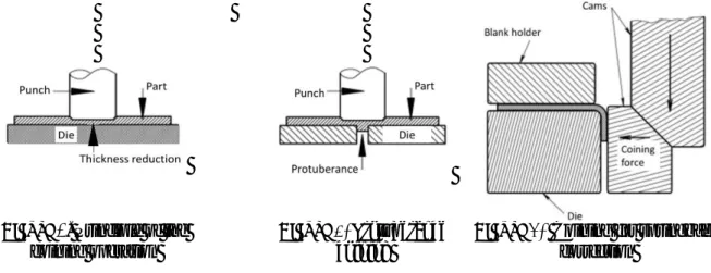
Making parts through sheet metal forming usually requires blanking, drawing and bending operations. However, in certain cases, specific operations are carried out, such as coining, an operation during which the sheet metal material is “compressed” along its thickness by the action of a punch and a die (Figure 1). Coining may be required to flatten the surface of a part, locally reduce a thickness, form a specific surface relief (Figure 2) or correct geometrical defects caused by springback (Figure 3). Coining generates significant forces that are much higher than those generated in the other forming operations. This can therefore have repercussions on the necessary force of the presses, the stiffness and endurance of the tools and the actual accuracy of the tools which undergo these very high forces.
International Deep-Drawing Research Group (IDDRG 2020)
IOP Conf. Series: Materials Science and Engineering 967 (2020) 012003
IOP Publishing doi:10.1088/1757-899X/967/1/012003
2 Figure 1. Principle of the
coining operation
Figure 2. Protuberance
coining
Figure 3. Coining for springback
correction
This is why these forces need to be properly estimated right from the design of the tools. With regard to thin sheet metal forming, some practical methods to calculate the coining force are commonly used, but remain inaccurate, such as the rough estimation of the bending force during coining [1], [2] which is still employed today, or the use of abacuses or calculation principles based on the knowledge of the compression stress and the coined area [3], [4]. The latter method remains the basis for force calculation in forging [4] with the adaptation of calculation formulae based on the shape of the part, the material flow modes and the friction [5].
In the presented study, the coining shape considered (Figure 4) features a constant compressed cross-section. In this case, a simplified form of the force calculation formula may allow the coining force to be calculated with an acceptable level of accuracy [4], [5].
The simplified force calculation form selected at the beginning of the study is described in (1):
𝐹 = 1.3 𝜎. 𝑆𝑝 (1) 𝜎 = 𝐾 [ln (1 + 𝑡0− 𝑡1 𝑡0 )] 𝑛 (2) 𝑆𝑝= (𝑙𝑝 − 2𝑅 + 2𝑆). 𝑤𝑠 (3) 𝑆 = 𝑅. sin {cos−1[ 𝑅 − (𝑡0− 𝑡1) 𝑅 ]} (4)
Where K is the strengthen coefficient and n is the strain hardening exponent. The strain is integrated into (2) via the expression: ln (1 +𝑡0−𝑡1
𝑡0 ). t0 and t1 are, respectively, the initial thickness and post-coining thickness of the sheet. The projected area below the punch Sp is calculated using (3) and (4), with lp being the coining width, R the radius of the coining punch, S the calculated contact length (4) of the punch radius and ws the width of the coined sheet (Figure 4). 1.3 is a coefficient widely used in forging; it takes into account a constant effect of the friction between the sheet and the tool.
International Deep-Drawing Research Group (IDDRG 2020)
IOP Conf. Series: Materials Science and Engineering 967 (2020) 012003
IOP Publishing doi:10.1088/1757-899X/967/1/012003
3
The objective of the presented study is to improve the proposed calculation formula with an experimental and numerical study of the influence of coining parameters.
2. Experimental procedure
Two sheet metal grades were used in this study: X6Cr17 stainless steel with thicknesses of 1 and 1.5 mm and HC380LA high strength low alloy steel with thicknesses of 0.8 and 1.5 mm. The samples used in the coining tests are 40 x 100 mm in size. The tests were carried out in dry conditions.
2.1. Tool used, force measurements and characterisation of the coined area
The tool used in the study is comprised of the main components listed below (Figure 5):
- A flat punch with a radius of 1.5 mm and a width of 7.5 mm, made of X153CrMoV12 steel, treated to 60 HRC
- A flat die, made of X153CrMoV12 steel, treated to 60 HRC - Clamps to hold the coined samples
- A die with ball guide pillars
The setup is installed on a COFMO KI 2128 mechanical press with a maximum capacity of 63 tonnes.
Figure 5. Sheet coining setup
The coining forces are measured by a piezoelectric force sensor located above the punch. Thickness measurements were carried out in the coined areas of the sheets, using a dial indicator, before and after coining. The coined areas were also examined using a confocal microscope. Finally, the contact areas were measured on the upper faces.
2.2. Ring compression test
Since cold forging and sheet metal coining are similar operations, we used the ring compression test, a test widely used in forging to estimate the values of the friction coefficient at the interface between the sheet and the tool. These values will then be used in the coining simulation software.
This test, developed by Male and Cockroft [6], consists in deforming metal rings between two flat dies. When the ring is compressed, the variation of the inside diameter is extremely susceptible to the friction between the ring and the tools. A series of curves is obtained by numerical simulation of the ring compression test and describes the change in the inside diameter as a result of the change in height, for a given friction coefficient. The experimental data is obtained with a series of ring compression tests, with different compression heights.
The rings feature the following dimensions: 3.6 mm for the inside diameter and 10.5 mm for the outside diameter. The thickness of the sheet used determines the thickness of the ring.
International Deep-Drawing Research Group (IDDRG 2020)
IOP Conf. Series: Materials Science and Engineering 967 (2020) 012003
IOP Publishing doi:10.1088/1757-899X/967/1/012003
4 3. Numerical model
We used the Forge NXT2 software to perform the various simulations, namely simulations of the coining operation in order to better understand the evolution of the contact between the metal sheet and the tool, and simulations of the ring compression test.
3.1. Geometries
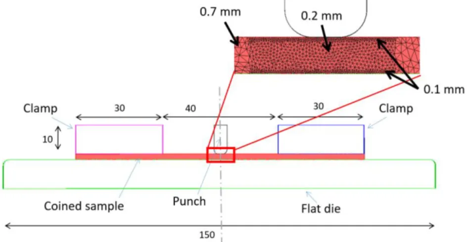
The flat coining numerical model is presented below (Figure 6). The simulations were carried out based on a 2D planar model (plane strain condition). The element type is here 2D and triangular. The tools (flat die, clamps, and the punch) are considered rigid bodies. The flat die and the clamps are fixed. A 0.5 mm gap is imposed between clamps and the coined sample. The mesh size in the coined sample has been reduced under the punch to 0.2 mm.
Figure 6. 2D numerical model of the sheet and the coining tools 3.2. Behaviour laws
We used an elastic-plastic model in the coining simulations. The plastic behaviour data of the coined metals were determined with tensile tests. Here, the behaviour is assumed to be isotropic. The tests were carried out at 0°, 45° and 90° with respect to the rolling direction, with a tensile test speed of 5 mm/min. The behaviour coefficients were determined by adjustment on the 3 tensile stress curves. The behaviour law used in the numerical simulations is of the Hollomon type (5).
𝜎 = 𝐾𝜀𝑛 (5)
The behaviour coefficients stemming from the tensile tests are described in the Table 1:
Table 1. Behaviour coefficients used in the 2D models of the sheet metal coining operations
K (in MPa) n
HC380LA 727 0.155
X6Cr17 717 0.194
The Young’s modulus of elasticity is considered equal to 200 GPa. In this law, the initial yield strength of the material is neglected and the plastic state of the material is, in our assumption, mainly responsible for the stress taken into account in the calculation.
International Deep-Drawing Research Group (IDDRG 2020)
IOP Conf. Series: Materials Science and Engineering 967 (2020) 012003
IOP Publishing doi:10.1088/1757-899X/967/1/012003
5 3.3. Friction
Several laws exist to describe the friction which occurs between two bodies. In our sheet metal coining case, the contact pressures are significant. With the slip, the asperities present on the surfaces of the two bodies are gradually crushed (Coulomb friction) until the contact area between the two bodies no longer increases. Friction then occurs as a result of the deformation of the surface of the softer body (Tresca friction). Thus, we propose the use of a Coulomb friction law with a Tresca law type limitation (6), with the latter integrating a yield criterion. This law was introduced into the sheet metal coining simulations and into the simulations used to define the ring compression test abacuses.
Where c is the critical shear stress; µ is the Coulomb friction coefficient;
n is the normal stress;
0 is the Von Mises stress; and m̅ is the Tresca friction coefficientAs a result, the simulated curves of the ring compression tests served to determine two friction coefficients simultaneously. The studies described by Zhang et al. [7] show that a relationship 𝑚̅ = 2 µ could be applied.
4. Results and discussions 4.1. Ring compression tests
The results of the ring compression test are given in Figure 7. The relative change in the inside diameter of the ring (Di/Di) is presented as a function of the coining ratio (t1/t0). Note that, for the HC380LA grade, the experimental points are correctly positioned with respect to the calculated curve for 𝑚̅ = 0.3 and µ = 0.15. However, for the X6Cr17 grade, it is more difficult to position the experimental points over a single curve. As a matter of fact, for a coining ratio ranging between 0.9 and 0.7, the friction coefficients are rather close to 𝑚̅ = 0.6 and µ = 0.3 and, for coining ratios below 0.7, the friction coefficients are higher: 𝑚̅ = 1 and µ = 0.5. These last values, which are better correlated with the experimental measurements, were selected for the X6Cr17 grade.
Figure 7. Results of the ring compression tests on HC 380 LA (a) and X6Cr17 (b)
The friction coefficients are extremely high for the X6Cr17 grade. This can be explained by a magnetic attraction phenomenon between the flat die and the X6Cr17 work pieces.
𝜏𝑐 = 𝑀𝑖𝑛(𝜇𝜎𝑛, 𝑚̅ 𝜎0
√3) (6)
International Deep-Drawing Research Group (IDDRG 2020)
IOP Conf. Series: Materials Science and Engineering 967 (2020) 012003
IOP Publishing doi:10.1088/1757-899X/967/1/012003
6 4.2. Analysis of the coined areas
The coined areas were examined in order to determine whether or not they were correctly estimated by the force calculation formula (1). Figures 8 a), b) and c) illustrate the top and bottom sides of a non-lubricated X6Cr17 work piece after coining.
Figures 8. Examples of coined areas on a X6Cr17 work piece – Punch/sheet dry contact (a and b),
die/sheet dry contact (c)
The coined area features different zones: a zone 1 marked with a black line and located in the centre, the simulation of which shows that the sheet/tool sliding velocities are almost equal to zero, and a zone 2, more visible on Figures 8 b), which is characterised by two lines running lengthwise in the coined area and limiting said zone on its sides. During the coining operation, the surface asperities are compressed by the punch. Zone 2 still exhibits some visible asperities, which means that there is very little or even no contact with the punch in this zone at the end of the coining operation. The asperities run along the direction of the material flow and correspond to a surface which was in contact with the punch during the coining operation and which flowed outwards. To conclude, we can say that the contact area at the end of the coining operation is located in zone 1 and that it is therefore smaller than the one calculated with the force calculation formula.
The contact area was quantified through numerical simulation (Figure 9) and through measurements with a confocal microscope. The results show that the contact area on the radius of the punch is not effective and that the areas calculated with the current force estimation formula are overestimated by 23.5% on average when compared with the measured areas. If the punch radii are not taken into account in the area calculation (S = 0 (4)), then the calculated area is markedly more accurate and barely underestimated, by 8.3% on average.
These results show that it is advisable to disregard the area below the radius of the punch.
Figure 9. 2D simulation of the contact area between the coining tool and the coined sheet
a) c)
International Deep-Drawing Research Group (IDDRG 2020)
IOP Conf. Series: Materials Science and Engineering 967 (2020) 012003
IOP Publishing doi:10.1088/1757-899X/967/1/012003
7
4.3. Adjustment and validation of the force estimation formula
Two major changes were made to the coining force calculation. The first change is the omission of the punch radii in the calculation of the projected area (S = 0). The other major change is a more accurate integration of friction in the force calculation. The slice/slab method [8-9] is an analytical calculation method serving to estimate the hot compression forces applied to cylindrical slugs. This analytical calculation integrates the friction coefficient 𝑚̅. The integration of the friction coefficient into the calculation formula using the slice/slab method allows us to propose a new force estimation formula (7):
𝐹𝑠𝑙𝑖𝑐𝑒𝑠= 𝐾. [𝑙𝑛 (1 + 𝑡0− 𝑡1 𝑡0 )] 𝑛 . ( 1 + 1 3√3𝑚̅ 2 (𝑆𝜋 )𝑝 1/2 𝑡1 ) . 𝑆𝑝 (7)
The slice/slab method does not take the Coulomb friction into account, therefore only the Tresca coefficient is integrated into the new formula.
The forces measured experimentally and calculated with the current formula and with the new formula are presented in Figure 10. This figure also shows the results of the numerical simulation. These results are given for the two material grades, two coining ratios and different sheet thicknesses.
The results reveal that the current calculation formula considerably underestimates the coining forces. The difference in the forces is greater for the X6Cr17 grade (-70.9% maximum) than for the HC380LA grade; this can be related to the friction coefficients found in the ring compression tests and to the need to accurately integrate this factor. The force is much better estimated with the new formula, with a maximum difference of 21% with respect to the measured values. In the cases with a coining ratio of 0.7, the difference between the measured forces and the forces calculated with the new formula amounts to 14% on average. The simulated forces are also very close to the measurements, except for the X6Cr17 coining case with a coining ratio of 0.9. In this latter case, the simulation and the new calculation formula overestimated the forces. This difference may be explained by the friction coefficient, the value of which can be better adjusted.
The results obtained seem to substantiate the validity of the new force calculation formula. Nevertheless, the accuracy of the new calculation formula appears to be strongly dependent on the accuracy of the value of the friction coefficient, which can be complex to measure or estimate.
International Deep-Drawing Research Group (IDDRG 2020)
IOP Conf. Series: Materials Science and Engineering 967 (2020) 012003
IOP Publishing doi:10.1088/1757-899X/967/1/012003
8 5. Conclusion
The objective of this study was to propose an improved empirical calculation formula for sheet metal coining, based on stress and coined area. For the two sheet metal grades considered, the comparison of the coined area obtained with the current calculation formula and the coined area obtained after simulation analysis showed that the former was overestimated by approximately 23%. The study also highlighted the influence of the friction, which is not taken into account in the current formula. Thus a Coulomb friction coefficient limited to Tresca was proposed and the values were determined from the ring compression test. Then this friction was integrated into a new force calculation formula derived from the slice/slab method.
The comparison with the measured forces revealed that the new calculation formula gave better results with regard to the estimation of the coining forces. However, as friction has a strong influence in the estimation of the forces, the friction coefficients must be accurately measured, for all coining ratios. In order to be fully validated, this new formula also needs to be tested on other materials. In addition, while the results are much improved for this particular geometry, whether this is the case for all applications is not demonstrated, e.g., much large R, much large lp, etc. Also, varying frictional conditions with various lubricants should be investigated.
References
[1] Bliss Power Press Handbook 1950 E W Bliss Co Toledo Ohio
[2] Aberwald TS 1996 Manufacturing strategies Volume 6 PMA Symposium Proceeding Metalform,
Nashville, Tenessee
[3] Sachs J 1966 Principles and methods of Sheet metal Fabricating Second edition Chapter Impact
intrusion and coining Reynold Publishing Corporation New York, 10022
[4] Smith D 1990 Die Design Handbook Third edition Chapter Compression dies ISBN n°
0-87263-374-6
[5] Schultes T, Sevenler K, Altan T 1981 Prediction of Forging Load and Stresses Using a Programmable Calculator Topical Report No. 4, Battelle Columbus laboratories
[6] Male AT and Cockroft MG 1964 J. I. Met. 93 38
[7] Zhang DW and Ou H 2016 Tribol. Int. 95 13
[8] Boujut JF and Tichkiewitch S 1992 J. Mater. Process. Tech. 34 163