HAL Id: tel-01555571
https://pastel.archives-ouvertes.fr/tel-01555571
Submitted on 4 Jul 2017HAL is a multi-disciplinary open access
archive for the deposit and dissemination of sci-entific research documents, whether they are pub-lished or not. The documents may come from teaching and research institutions in France or abroad, or from public or private research centers.
L’archive ouverte pluridisciplinaire HAL, est destinée au dépôt et à la diffusion de documents scientifiques de niveau recherche, publiés ou non, émanant des établissements d’enseignement et de recherche français ou étrangers, des laboratoires publics ou privés.
Laminated Timber panels : Modeling and experimental
validation in ambient and fire conditions
Lorenzo Franzoni
To cite this version:
Lorenzo Franzoni. Mechanical behavior of regularly spaced Cross Laminated Timber panels : Modeling and experimental validation in ambient and fire conditions. Materials. Université Paris-Est, 2016. English. �NNT : 2016PESC1113�. �tel-01555571�
Th`
ese pr´
esent´
ee pour obtenir le grade de
Docteur de l’Universit´
e Paris-Est
Sp´
ecialit´
e: Structures et Mat´
eriaux
par
Lorenzo Franzoni
´
Ecole Doctorale : Sciences, Ing´enierie et Environnement
Mechanical behavior of regularly spaced
Cross Laminated Timber panels
-Modeling and experimental validation in ambient and fire
conditions
Th`ese soutenue le 24-11-2016 devant le jury compos´e de: Prof. Hans Joachim Blass KIT Karlsruhe Rapporteur Prof. Patrice Cartraud EC Nantes Rapporteur Prof. Joseph Gril LMGC Montpellier Examinateur Dr. Reinhard Brandner TU Graz Examinateur Prof. Michael Flach Innsbruck University Examinateur Dr. Arthur Leb´ee Laboratoire Navier Co-encadrant Dr. Florent Lyon CSTB Co-encadrant Prof. Gilles Foret Laboratoire Navier Directeur de th`ese
Abstract
Cross Laminated Timber (CLT) panels are engineered timber products composed of layers made of wooden lamellas placed side by side, glued on their upper and lower faces and stacked crosswise. In the present thesis, the influence of lateral spaces between lamellas of each layer on the panel’s mechanical response is investigated with modeling and tests. Both configurations of standard panels having short spaces and innovative panels with large spaces are analyzed.
As a first approach, the bending behavior of standard CLT was modeled by means of an equivalent-layer model based on simplified hypotheses. The good agreement of the predicted behavior with an experiment of the literature allowed an investigation on several CLT properties by means of parameter studies.
Then, 4-points bending tests on standard and innovative CLT floors were performed in order to quantify the influence of periodic spaces on the panels’ mechanical response. Moreover, available in-plane shear tests of the literature have been considered as ref-erence in-plane behavior.
The spaced CLT have been subsequently modeled as periodic plates with a periodic homogenization scheme handled by a thick plate theory. Existing simplified methods were compared as well with refined modeling and test results. It appears that the bending behavior of spaced CLT can be predicted with a simplified method, while only the thick-plate homogenization can predict the in-plane and transverse shear behavior. Then, closed-form solutions for predicting spaced CLT elastic behavior were derived to encourage the application of these products in timber construction.
One further study within this thesis concerns the analysis of fire-exposed standard CLT floors. The comparison between test results and both advanced and simplified modeling led to a suggestion for a possible improvement the standard fire design model.
R´
esum´
e
Les panneaux en bois lamell´e crois´e (en anglais CLT - Cross Laminated Timber) sont des ´el´ements de structure compos´es de couches en bois coll´ees entre eleese et empil´ees de fa¸con crois´ee. Chaque couche est compos´ee de planches en bois juxtapos´ees et g´en´eralement non coll´ees sur leurs chants. Dans cette th`ese, nous ´etudions l’influence des espacements entre planches sur le comportement m´ecanique des panneaux `a l’aide d’une approche par mod´elisation et exp´erimentation. Les panneaux CLT standards sont consid´er´es comme des panneaux avec des espacements de tr`es faible dimension par opposition aux panneaux avec espacements importants que nous appelons panneaux innovants.
Nous mod´elisons dans un premier temps le comportement en flexion de panneaux standards `a l’aide d’un mod`ele de couche homog`ene ´equivalente bas´ee sur des hy-poth`eses simplifi´ees de la m´ecanique d’une couche avec chants coll´es ou non coll´es. Nous observons un bon accord entre les r´esultats de notre mod´elisation et des r´esultats exp´erimentaux issus de la litt´erature. Des ´etudes param´etriques sont ensuite realis´ees portant sur certaines propri´et´es des panneaux.
Nous avons ensuite r´ealis´e des essais de flexion 4-points sur des panneaux CLT stan-dard et innovants pour quantifier l’influence des espacements sur la r´eponse m´ecanique des panneaux. Nous observons alors que l’influence des effets de cisaillement transverse sur le comportement ´elastique et `a la rupture augmente avec l’augmentation des vides dans le panneau.
Afin de prendre correctement en compte les effets du cisaillement, les CLT espac´es sont ensuite mod´elis´es comme des plaques ´epaisses p´eriodiques `a l’aide d’un mod`ele de plaque d’ordre sup´erieur. Ce mod`ele a ´et´e appliqu´e `a la g´eom´etrie des panneaux CLT espac´es avec un sch´ema d’homog´en´eisation p´eriodique. Des m´ethodes simplifi´ees exis-tantes ont ´egalement ´et´e compar´ees avec des r´esultats d’essais et le mod`ele de plaque. De plus, des r´esultats d’essais de cisaillement dans le plan des panneaux CLT standards issus de la litt´erature ont ´et´e compar´es avec nos r´esultats. La raideur de flexion des CLT espac´es peut ˆetre pr´edite avec des m´ethodes simples existantes alors que seule la mod´elisation que nous proposons permet de pr´edire le comportement en cisaillement transverse et dans le plan. Nous avons ensuite propos´e des formules analytiques dans le but de pr´edire le comportement ´elastique des CLT espac´es. Ces formules donnent une bonne approximation du comportement des CLT espac´es et peuvent ˆetre utilis´ees dans le cadre d’une d´emarche pratique de dimensionnement.
Enfin, une ´etude concernant l’analyse du comportement au feu des panneaux CLT standard est pr´esent´ee. La comparaison entre des r´esultats d’essais au feu et une modelisations avanc´ee et simplifi´ee a permis de proposer une possible am´elioration de la m´ethode standard de dimensionnement au feu.
I would like to acknowledge my supervisors Gilles, Arthur and Florent for giving me the opportunity to live the great working and human experience which has been my thesis. I want to thank my thesis director Gilles for his valuable advices during these three years and for the essential “background” work necessary to set up and fund my studies. Arthur has been a precious presence during my thesis, many thanks to you and to your patience during many computational issues. In my personal view, any modeling result obtained solving many computational issues loses a bit of value if not compared to experimental data. For this reason I’m really grateful to the CSTB institution and to my CSTB supervisor Florent for the organization of the experimental investigation and also for funding part of my thesis. Many thanks also to Dhionis, your advices have been a valuable help to carry on the study in fire conditions.
I want to acknowledge all the jury board for having accepted to examine my the-sis. In particular, I would like to thank the representatives of the timber engineering research community, their presence in the jury board is important for me. Indeed, the exchanges during the timber engineering conferences I attended were simply enrich-ing and inspirenrich-ing, exactly as the people I met. I definitively hope that at least part of my future works will enrich the timber engineering research and consequently will contribute to the development of timber construction.
All my trips during my thesis would not be possible without the perfect and kind work of Marie-Francoise, many thanks also to you.
Finally, many thanks to all my Laboratory colleagues for the nice days together, to my friends, my family and my girlfriend for encouraging and supporting me since the beginning till today.
Lorenzo Franzoni Paris, November 2016
Contents
1 Introduction 1
2 Bending behavior of standard CLT: modeling and parameter studies 13
2.1 Introduction . . . 13
2.2 Reference experimental test . . . 15
2.3 Modeling of CLT panels bending behavior . . . 16
2.3.1 Mechanical behavior of solid wood . . . 16
2.3.2 Van der Put’s mixed failure criterion for wood . . . 17
2.3.3 Equivalent CLT Layer model . . . 19
2.3.3.1 Continuous Equivalent Layer . . . 20
2.3.3.2 Discontinuous Equivalent Layer . . . 20
2.3.4 Pagano’s exact solution for laminates in bending . . . 21
2.3.4.1 Uni-axial bending . . . 22
2.3.4.2 Bi-axial bending . . . 22
2.4 Comparison with the reference test . . . 23
2.4.1 Global stiffness . . . 23
2.4.2 Failure stages comparison . . . 23
2.4.2.1 Continuous layer . . . 24
2.4.2.2 Discontinuous layer . . . 25
2.4.2.3 Discussion . . . 26
2.5 Investigation on CLT panel properties . . . 27
2.5.1 Influence of transverse shear effects . . . 27
2.5.2 Varying the number of layers for a fixed total thickness . . . 28
2.5.3 Varying cross layer orientation . . . 29
2.6 Conclusion and perspectives . . . 31
3 Experimental investigation 33 3.1 Introduction . . . 33
3.2 4-points bending tests on full scale floors . . . 34
3.2.1 Materials and methods . . . 34
3.2.2 Results . . . 36
3.2.3 Discussion . . . 38
3.3.1 Materials and methods . . . 38
3.3.2 Results . . . 40
3.3.3 Discussion . . . 42
3.4 CLT in-plane shear tests of literature . . . 43
3.5 Conclusion . . . 44
4 Homogenization of regularly spaced CLT panels 45 4.1 Introduction . . . 45
4.2 Modeling of spaced CLT . . . 47
4.2.1 Summary of the Bending-Gradient model . . . 47
4.2.2 Homogenization scheme . . . 48
4.2.2.1 Membrane and thin plate unit-cell problem . . . 49
4.2.2.2 The generalized shear unit-cell problem . . . 50
4.2.3 Application to a regularly spaced CLT panel . . . 51
4.2.3.1 Boundary conditions and loads for the thin-plate and membrane unit-cell problem . . . 53
4.2.3.2 Boundary conditions and loads for the thick-plate unit-cell problem . . . 53
4.3 Results . . . 56
4.3.1 Bending stiffness . . . 56
4.3.2 In-plane shear and torsional stiffnesses . . . 57
4.3.3 Thick-plate homogenization . . . 61
4.3.4 Influence of predicted stresses on variation of failure modes . . . 68
4.4 Conclusion . . . 70
5 Closed-form solutions for spaced CLT 73 5.1 Introduction . . . 73
5.2 Spaced CLT as beam space frame . . . 74
5.3 Thin space frame . . . 75
5.3.1 Energy of connected beams . . . 76
5.3.2 Derivation of the spaced CLT stiffnesses . . . 79
5.3.3 Membrane and bending stiffness of spaced CLT . . . 80
5.3.4 In-plane shear and torsional stiffness of spaced CLT . . . 81
5.4 Thick space frame . . . 83
5.4.1 Transverse shear kinematics of blocks and related energy . . . . 85
5.4.2 Energy of connected beams . . . 88
5.4.3 Derivation of the shear force compliance . . . 89
5.5 Closed-form prediction of longitudinal and rolling shear stresses . . . . 92
5.5.1 Maximum longitudinal stress . . . 93
5.5.2 Maximum rolling shear stress . . . 93
5.6 Comparison . . . 94
CONTENTS
5.6.2 In-plane shear and torsional stiffness . . . 95
5.6.3 Shear force compliance . . . 98
5.6.4 Maximum longitudinal and rolling shear stresses . . . 100
5.7 Conclusion . . . 103
6 Fire behavior of standard CLT floors: a stiffness-based approach 105 6.1 Introduction . . . 105
6.2 Fire tests on CLT floors . . . 107
6.2.1 Description of fire tests . . . 107
6.2.2 Temperature profiles . . . 107
6.2.3 Charring rates . . . 110
6.2.4 Deflection of fire exposed CLT floors . . . 110
6.3 Modeling . . . 112
6.3.1 Advanced modeling of heat transfer . . . 112
6.3.2 Themo-mechanical modeling . . . 113
6.3.3 Reduced Cross Section modeling . . . 114
6.3.3.1 Existing RCSM approaches . . . 114
6.3.3.2 Proposal for improving the RCSM . . . 115
6.4 Comparison . . . 116
6.5 Discussion . . . 119
6.6 Conclusion . . . 120
7 Conclusions and outlooks 121 7.1 Limitations . . . 123
7.2 Outlooks . . . 124
Chapter 1
Introduction
Timber is a bio-sourced construction material always present in human history. At the beginning of the 20th century, the classic log or lattice frame timber construction methods have been progressively replaced by the more economical human-made con-struction materials like masonry, steel and concrete, at least in Europe (Schickhofer et al 2009). Starting from about ten years ago, timber has sharply regained portions of the construction market, even within cities of European countries like Italy, Austria, Germany or France. This is mostly due to the introduction of a new massive timber construction method based on Cross Laminated Timber (CLT or crosslam) panels, two-dimensional engineered timber products composed of an uneven number of lum-ber layers stacked and glued crosswise (Figure 1.1). Each layer is made of lumlum-ber
Figure 1.1: Cross Laminated Timber panel (http://hybrid-build.co/)
boards placed side by side which can be glued or not on their lateral faces depending on the fabrication process. CLT panels have been introduced at the beginning of the 90’s in central Europe, based on the well-known principle of orthogonal lamination of plywood applied to thick panels. The resulting thick and orthogonal element has more uniform hygroscopic behavior than glulam and can be used as a full size wall, floor or roof capable of bearing in-plane or out-of-plane loads. The main advantage of CLT building method with respect to traditional timber frame structures is the mod-ular on-site assembly of full size prefabricated CLT that yields very short construction times. The CLT development in modern timber construction has so increased that tall 10-story buildings have been made for instance in London, Milan (Figure 1.2a) and Melbourne, and other having 20-story are in progress in Canada (Figure 1.2b) and
France. Such heights are unprecedented in timber engineering, showing the potential of CLT construction system. Compared to linear beam elements made of Glued
Lami-(a) (b)
Figure 1.2: Tall CLT buildings: (a) 9-story building in Milan (Bernasconi 2016) and (b) on-going project in Vancouver of a 18-story building with concrete cores (Fast et al 2014)
nated Timber (GLT), CLT panels have capacity of carrying in-plane and out-of-plane loads. Moreover, the crosswise lay-up yields a “system” effect which increases the raw material strength and stiffness, as highlighted by one of the first comprehensive ex-perimental campaign on CLT in bending (Joebstl et al 2006). On this basis, recent state-of-art reports on CLT development suggested specific strength classes for CLT products (Brandner et al 2016; Schickhofer et al 2016). This effect increases when the two-dimensional load distribution capacity is exploited, as showed by Hochreiner et al (2013), Bogensperger and Jobstl (2015) and as will be pointed out in Chapter 2 of the present thesis.
Building with CLT means also connecting the panels between themselves or with other structural elements with connections capable of transferring the loads and en-suring the structural safety. Therefore, panels’ assembling plays a crucial role within CLT construction techniques and, indeed, connection systems are one of the main CLT research topics (Blass and Schadle 2011; Flatscher et al 2014; Polastri 2014). When dealing with dynamic loadings, the connections play a crucial role (Fragiacomo et al 2011; Gavric et al 2015; Scotta et al 2016), since the energy deriving from the wind or seismic acceleration has to be dissipated thanks to the ductility of connections systems. For instance, connections for anchoring CLT walls can consist in classical metallic fas-teners (hold-down and angle brackets) or innovative connection systems (Figure 1.3a), while floor-to-floor connections are usually realized with screws (Figure 1.3b).
(a) (b)
Figure 1.3: Connections in CLT construction: (a) metallic fasteners for anchoring CLT walls and (b) butt-joint between CLT panels (XlamDolomiti 2016)
order to guarantee the structural safety of the structure and also an adequate evacua-tion time. Since the massive CLT lay-up ensures slow charring rates (Frangi et al 2009b; Craft et al 2011), crosslam panels have also an improved fire resistance compared to linear beam elements. However, the current design model for timber members exposed to fire (EN1995-1-2 2004) has been recently identified to be sometimes non-conservative when dealing with timber floors exposed to fire (Schmid et al 2012). Chapter 6 of the present thesis suggests a possible approach for improving the current version of the structural fire design model of Eurocode 5 1-2 (EN1995-1-2 2004).
Finally, the prefabrication allows the possibility to use CLT panels as reinforcing elements for existing traditional buildings (Branco et al 2014; Soriano et al 2016) and also for the seismic retrofit and comfort rehabilitation (Viskovic et al 2016).
Figure 1.4 presents the CLT skeleton of the 9-storey building in London, showing CLT panels used as horizontal (floors) or vertical (walls) structural elements.
Figure 1.4: Structural skeleton of the 9-story Murray-Groove CLT building in London (http://tesseract-design.com)
response of standard and innovative CLT panels under out-of-plane bending is the main topic of the present thesis. When submitted to out-of-plane bending, the crosslam orthogonal structure leads to cross layers having negligible load-carrying capacity. This is due to the ratio in the range of 25-30 between wood’s Young’s modulus parallel and perpendicular to grains. Moreover, the cross layers are submitted to transverse shear in wood transverse RT -plane (also called rolling shear, Figure 1.5), which shows low values of stiffness and strength, making CLT shear compliant. For softwood, the ratios between RL and RT shear stiffness and strength are in the range of 5-10.
R L R T T L
Figure 1.5: Rolling shear in CLT. From Mestek (2011) and Ehrhart et al (2015)
During last years many works have been done on rolling shear in CLT (Aicher and Dill-Langer 2000; Zhou et al 2014; Ehrhart et al 2015; Li et al 2014) in order to study the parameters that mostly influence rolling shear stiffness and strength. Many ex-perimental bending tests on CLT panels proved that common failure modes are either rolling shear of transverse layers or tensile bending failure of bottom layers (Mestek 2011; Blass and Fellmoser 2004b; Hochreiner et al 2013; Czaderski et al 2007; Okabe et al 2014; Sikora et al 2016). The transition between bending and shear failure is influenced by the panel’s slenderness but also by boards strength class (Hochreiner et al 2014). The strength classes (EN 2009) classify timber on the basis of the pres-ence of natural heterogeneity (knots, fiber deviation) and the expected influpres-ence on the mechanical properties. The tensile strength is the most affected property by the heterogeneities, while timber shear stiffness and strength are generally considered to be independent from the strength class (Blass and Gorlacher 2000; Blass and Fellmoser 2004b; Grandvuinet and Muszynski 2016). Therefore, increasing the strength class of raw lamellas means favors rolling shear failure instead of tensile failure of CLT floors. The shear compliance of CLT is due to the presence of cross layers at 90◦, and hence varying the orientation of transverse layers may mitigate the shear effects and improve the bending performance. The recent studies of (Chen and Lam 2013) and Buck et al (2016) investigated experimentally on this topic (Figure 1.6), while in Chapter 2 of the present thesis a detailed numerical analysis on this subject is performed.
Dealing with calculation methods for out-of-plane loads, 3D Finite Elements (FE) or 3D analytical solutions can well reproduce the mechanical behavior of CLT panels (Sebera et al 2013; Sturzenbecher et al 2010) but they are computationally quite ex-pensive. Crosslam panels can be also modeled as layered anisotropic plates, and their behavior can be well predicted by 2D plate theories, as showed by Sturzenbecher et al
Figure 1.6: Innovative orientation of transverse layers at 45◦. From Buck et al (2016) (top) and Chen and Lam (2013) (bottom)
(2010). Due to the non-negligible shear compliance of crosslam, a thick plate theory to correctly predict transverse shear effects is needed. More than 3D or 2D approaches, several 1D simplified design methods exist, and some of them are implemented in Euro-pean or national design codes (EN1995-1-1 2004; DIN 2004). Such methods are based on lamination theory for layered plates under uni-axial loads and are the k-method (Blass and Fellmoser 2004a) that neglects shear effects, the γ-method of the Eurocode 5 (EN1995-1-1 2004) which partially takes into account shear effects and the shear analogy method (Kreuzinger 1999) which is considered the most predictive method. The shear analogy method will be compared to refined modeling of spaced CLT in Chapter 4 and Chapter 5.
When the CLT floor supports directly the CLT wall, there is a local punching and compression perpendicular to grain, which is a significant research axis (Bogensperger et al 2011; Brandner and Schickhofer 2014; Serrano and Enquist 2010) that tries to show the enhanced compressive properties of CLT. Indeed, compared to glulam, CLT cross layers act as reinforcements with a “locking effect” that increase the CLT stiffness and strength perpendicular to grain (Schickhofer et al 2016). Again, within a CLT panel used as a wall under compressive loads, only the layers having the fibers aligned with the load direction have load-carrying capacity. Moreover, when the height-to-thickness ratio of the panel is sufficiently high, buckling of CLT wall can occur. Recent studies (Perret et al 2016; Thiel and Krenn 2016) pointed out that the rolling shear compliance of transverse layers has a significant influence on the buckling loads of CLT walls. The main focus of research studies concerning crosslam walls deals with the in-plane shear behavior (Figure 1.7a) and an adequate experimental set-up (Figure 1.7b) to determine in-plane shear stiffness and strength (Brandner et al 2013; Gagnon et al 2014; Araki et al 2014; Andreolli et al 2012; Brandner et al 2015). Indeed in-plane shear properties are important for CLT diaphragms and shear walls, especially when submitted to dynamic in-plane loads (Moroder et al 2016). The in-plane shear stiffness of spaced CLT panels is predicted in the present thesis with numerical (Chapter 4) and
(a) (b)
Figure 1.7: (a) CLT wall under loads in-plane (Bogensperger et al 2010) and (b) experimental set-up suggested by Andreolli et al (2012)
closed-form (Chapter 5) approaches, showing that the spaces between lamellas strongly influence the in-plane shear behavior, even for short spaces of standard panels.
The fast development of CLT application in modern construction led to many recent research studies on CLT challenging topics. As a consequence, an established knowledge on the main advantages and issues related to this product exists and brought to the publication of a north-American standard (ANSI/APA 2012) and manual (Gagnon and Pirvu 2013) and an European manual (Schickhofer et al 2009). The publication process of European standard requirements for CLT is on-going and the final draft is now available (EN-16351 2016), while the new version of the Eurocode 5 1-1 containing a section for CLT design is currently under revision (EN1995-1-1 2015).
The process of standardization tries to harmonize CLT production, fields of appli-cation and design methods, in order to make this product competitive against mineral-based construction materials. However, there still remain issues not covered or partially covered by the standards. For instance, the final version of EN-16351 (2016) allows the non-gluing of lateral boards of each layer and the presence of small gaps up to 6 mm (Figure 1.8) without specifying their influence on the mechanical behavior. Dealing with the out-of-plane behavior of crosslam the presence of such gaps has been found experimentally (Hochreiner et al 2013) and numerically (Flores et al 2016) to reduce the global-load carrying capacity, due to the presence of free edges between spaces that yields singularities of stress perpendicular to grain (Figure 1.9). This topic will be discussed in Chapter 4 of this thesis, where a comparison between modeling and test results quantifies the influence of small lateral gaps on the transverse shear behavior of standard CLT. Nevertheless, the most sensitive properties of crosslam having short
Figure 1.8: CLT panels with short spacing up to 6 mm as described in EN-16351 (2016)
(a)
(b)
Figure 1.9: Stress concentration in laterally unglued transverse CLT boards due to free edges found (a) experimentally by Hochreiner et al (2013) and (b) numerically by Flores et al (2016) (b) for out-of-plane loads
spaces are related to in-plane behavior. Indeed, discontinuous CLT panels submitted to in-plane shear and in-plane bending (or torsion) shows an additional compliance mechanism related to torsion-like and in-plane rotation of lamellas. On the basis of this mechanism, Moosbrugger et al (2006) from Graz University suggested a simplified closed-form solution for predicting the in-plane shear stiffness and derived assuming an infinite number of layers. Then, the same research team of Graz University improved their approach fitting the closed-form solution on FE results (Bogensperger et al 2010; Silly 2010) for 3,5 or 7-ply configurations, leading to several fitting parameters. The current version of the reviewed Eurocode 5 1-1 for CLT design (EN1995-1-1 2015) in-cludes such closed-form solution with the FE fitting parameters for taking into account the number of layers. In the present study, FE homogenization and closed-form so-lutions for predicting the in-plane shear and torsional stiffnesses of spaced CLT are compared to the existing closed-form approaches.
Increasing the spaces between narrow lamellas up to hundreds of millimeters yields innovative lighter CLT panels similar to space-frame structure (Figure 1.10). The reg-ular voids can be used to receive equipment conduits or, when filled by insulating material, increase the acoustical and thermal efficiency as well as the fire resistance. Such innovative products match the increasing needs of lighter, more efficient and less expensive timber panels. Currently, there are no specific standards or design tools for the mechanical assessment of these innovative panels, which development is still
limited for the resulting lack of knowledge. Similar engineered timber products have
Figure 1.10: Innovative lightweight CLT panels having large spaces between lamellas
been tested by Blass and Gorlacher (2000) (Figure 1.11), who used the gamma design method for massive CLT (EN1995-1-1 2004) with wood mechanical properties reduced by the wood volume fraction in order to predict the bending behavior. It appeared that such approach can return a rather good prediction of the bending behavior of spaced timber floors. However, the simplified gamma method prevents an accurate descrip-tion of the transverse shear behavior of the spaced panel. The simplified approach of combining wood volume fractions with a method for massive crosslam is common in engineering applications, and therefore a more refined method may be needed when dealing with spaced CLT floors. No experimental or numerical studies exist on
in-Figure 1.11: Bending tests by Blass and Gorlacher (2000) on spaced timber floors and rolling shear failure of transverse boards
plane behavior of largely spaced CLT. However, the closed-form solution derived by Moosbrugger et al (2006) contains terms related to bending and shear flexibility of cantilevered beams having the spaces as span, and therefore may be capable of repro-ducing the in-plane behavior of innovative CLT having large spaces. A comparison between such closed-form solution and more accurate modeling is showed in Chapter 4 and Chapter 5.
Contrary to common thoughts, massive timber members such as CLT exposed to fire ensure a safer fire behavior than other construction materials. Indeed, the low thermal conductivity of wood and the self-protection function of charred wood yield low charring rates. For this reason, the fire behavior of timber is more “predictable” than the fire behavior of other materials like steel or concrete that can show explosive
(concrete) or instability (steel) phenomena difficult to predict. Moreover, the low ther-mal conductivity of wood makes the region affected by high temperatures confined very close to the char front, while the rest of cross section remains at ambient temperature. For this reason, the current fire design approach of the Eurocode 5 1-2 (EN1995-1-2 2004) allows to consider mechanical properties at ambient temperature combined with a reduction of cross section (Reduced Cross Section Method - RCSM). The reduced cross section is predicted with two steps: (i) a first reduction due to charring and (ii) an additional removal of a layer having no mechanical properties (also called zero strength layer) in order to take into account the reduced properties of wood in the region close to the char front (Figure 1.12). In the current version of the Eurocode 5 1-2, such layer has
Figure 1.12: Principle of the Reduced Cross Section Method of the Eurocode 5 (EN1995-1-2 2004)
a constant value of 7mm. However, recent studies (Schmid et al 2012; 2014; Lineham et al 2016) showed that this value sometimes leads to non-conservative results, and the “exact” value of the additional layer to remove is difficult to predict since it depends on many parameters. For instance, in order to improve the current RCSM approach, Schmid et al (2012) suggested an additional depth to remove from the cross section as a function of the total thickness of the panel. In Chapter 6 of this thesis, an innovative approach for suggesting a possible improvement of the RCSM is presented. Basically, it is based on the exposure time-dependency of the additional layer to remove when applying the RCSM. Moreover, being laminated members, the glued interface between layers can lead to premature falling-off of layers due to the low mechanical properties of glue at high temperatures. Several experimental studies on fire-exposed crosslam (Frangi et al 2009b; Craft et al 2011; Osborne et al 2012; Klippel et al 2014; Lineham et al 2016) showed a discrepancy about the occurrence and the influence on the fire design of this phenomenon. In Chapter 6 of this thesis, the experimental deflection of fire-exposed crosslam floors that showed falling-off of layers is predicted with the ap-proach of Frangi et al (2009b) for taking into account such delamination phenomenon and compared to other methods which neglect the falling-off.
the present thesis is to investigate on the influence of spaces between lateral boards on CLT mechanical behavior by means of modeling and tests. Both cases of small gaps of standard CLT and larger spaces of innovative panels are investigated. The comparison between refined modeling, test results and simplified methods aims to establish a reliable calculation tool for spaced CLT that could be used in practical applications. Additionally, a study on fire-exposed crosslam is presented in this thesis and aims to suggest a possible approach for improving the existing fire design model by means of a comparison between testing and advanced calculations. In the following, the manuscript outline is summarized, while an overview of the thesis is presented in Figure 1.13.
First simplified approach: In this first approach presented in Chapter 2, laterally glued or unglued layers are modeled by means of an equivalent layer model based on simplified hypotheses on mechanical properties. The stress were predicted with a 3D solution and are the input for a wood failure criterion. The good match with a reference test of literature allows parameter studies on common and innovative crosslam properties in order to point out some interesting features about CLT applications.
Experimental investigation: Chapter 3 presents the conducted full-scale and small-scale experimental tests that aimed to point out the influence of spaces on elastic and failure behavior of spaced CLT floors. A reference in-plane shear test on CLT of the literature is presented as well.
Modeling-1: Homogenization: Spaced CLT panels are then modeled as thin and thick periodic plates by means of a numerical homogenization scheme. Chapter 4 presents the main features of such refined modeling and the implementation in the case of spaced crosslam, as well as the comparison with experimental results and existing simplified approaches.
Modeling-2: Closed-form solution: Chapter 5 presents the modeling procedure to derive a closed-form solution for spaced CLT based on beam theory. The obtained simplified formulations can then be used for practical spaced CLT applications.
Fire behavior : The analysis of standard CLT fire behavior is presented in Chapter 6. The available experimental data is firstly summarized, then both refined modeling based on reduced properties and simplified modeling based on reduced geometry are presented. The comparison between the two approaches led to a suggestion for a possible improvement of the current fire design model for timber structures of Eurocode 5 1-2 (EN1995-1-2 2004).
Conclusion and outlooks: The thesis concludes with Chapter 7, where the principal results, conclusion and outlooks of the presented study are presented.
Finally, in the present thesis, only the deterministic mechanical behavior of CLT panels is considered. No possible influence of obtained results on thermal, acoustical or hygroscopic behavior is taken into account. The predicted displacements and stresses are elastic fields, and failure is defined to be the reach of the material strength by the
StateMofMtheMart ChapterM2 SimplifiedMmodelingMofMspacedMCLT:MtheMequivalentGlayer ChapterM2 ChapterM212 ReferenceMtest ChapterM213 Modeling ChapterM215 ParameterMstudies ChapterM214M Comparison StateMofMtheMart ChapterM2 ChapterM314 InGplaneMshearMtestsMofMliterature ExperimentalMinvestigation ChapterM3 ChapterM312 4GpointsMbendingMtests ChapterM313 SmallGscaleMtests RefinedMmodelingMofMspacedMCLT ChapterM4G5 FEMHomogenization ChapterM4 StateMofMtheMart ChapterM2 ChapterM614 Comparison FireMbehaviorMofMstandardMCLT ChapterM6 ChapterM612 TestMresults ChapterM613 Modeling TheMBendingGGradientMtheory ChapterM4121A TheMhomogenizationMscheme ChapterM41212 Results ChapterM413 ClosedGformMsolutions ChapterM5 SpacedMCLTMasMbeamMspaceMframe ChapterM512 ThinMspaceMframe ChapterM513 ThickMspaceMframe ChapterM514 Comparison ChapterM516 IntroductionM ChapterMA ConclusionMandMoutlooks ChapterM7 BendingMandMshearMstressMprediction ChapterM515 ApplicationMtoMspacedMCLT ChapterM41213
elastic stresses. Moreover, the considered CLT are single panels without connections with other elements.
Chapter 2
Bending behavior of standard CLT:
modeling and parameter studies
Note: This Chapter has been published in European Journal of Wood and Wood Products with the title Influence of orientation and number of layers on the elastic response and failure modes of CLT floors: modeling and parameter studies DOI: 10.1007/s00107-016-1038-x
Abstract. In this Chapter, the layers of CLT in bending are modeled as laterally glued or unglued layers by means of simplified hypotheses on mechanical properties. The simplified behavior is combined with the exact 3D elastic solution for layered plates in bending (Pagano 1969) and a failure criterion for wood. The predicted mechanical behavior is compared with an experiment of the literature in terms of global stiffness and variation of failure modes. Finally, parameter studies are performed on several panel’s properties which can be interesting for practical application.
R´esum´e. Dans ce Chapitre, nous mod´elisons les couches de CLT en flexion comme des couches homog`enes ´equivalentes dans lequelles les planches sont coll´ees ou non sur chants en prenant des hypoth`eses simplifi´ees sur les propri´et´es m´ecaniques. Ce comportement simplifi´e est coupl´e avec la solution exacte 3D pour multicouches en flexion (Pagano 1969) et un crit`ere de rupture pour le bois. Le comportement pr´edit est compar´e avec les r´esultats d’un essai issu de la litt´erature en termes de raideur globale et de variation des modes de ruine. Enfin, des ´etudes param´etriques sont conduites pour d´eterminer les propri´et´es des panneaux en fonction de leures caract´eristiques geom´etriques.
2.1
Introduction
The state-of-the-art presented in the previous Chapter revealed a comprehensive and well documented experimental study on CLT panels in bending (Hochreiner et al 2013). Therefore, the first purposes of this thesis have been reproducing the mechanical
re-sponse observed during such experiments of the literature and performing parameter studies on CLT properties interesting for applications. This work allowed the identifi-cation of challenging topics from both scientific and practical point of view.
CLT plates in bending are affected by heterogeneities at different levels. First, at the material scale, timber features a pronounced variation in mechanical properties. Then, within each layer, two other kinds of heterogeneities can be differentiated. The local orientation of orthotropic coordinate system is a priori unknown due to the variation of annual ring pattern. Moreover, the discontinuities in the non-gluing of lateral lamellas have a non-negligible influence on the mechanical response, as the studies presented in Chapter 1 show. At the structural level, the multilayer and orthotropic lay-up makes crosslam panels layered shear-compliant plates with anisotropic behavior, and therefore an adequate model has to be implemented in order to predict the mechanical response. At the layer scale, an ”equivalent-layer” mechanical model is suggested in this Chapter to take into account the CLT layer’s heterogeneities, leading to simplified hypotheses on layer’s behavior. Concerning the structural heterogeneity given by the multi-layer composition, the limits of the existing design methods presented in Chapter 1 lie in a simplified approach, which reduce the 2D problem into a 1D one and is suitable only for orthotropic (0◦ or 90◦) lay-ups. In the present Chapter, the exact 3D theory for laminated plates in bending (Pagano 1969; 1970) is applied to CLT panels, in order to predict their mechanical response and to analyze plates with non-orthotropic lay-ups. Being a 3D solution, Pagano’s theory can give a better estimation of stress distribution across the panel’s thickness than simplified 1D or 2D approaches, especially when the panel is submitted to concentrated loads, as in the case of the reference test (Hochreiner et al 2013). The elastic bending solution is therefore combined with a failure criterion for wood, in order to extend the comparison with the reference test in terms of failure stages.
In the present Chapter, the main topic of interest is CLT mechanical behavior at the layer and structure scale, leading to a simplified modeling at the material scale. Whereas the wood variability has not been taken into account in this study, having a detailed description of 3D stress enables the estimation of interesting features of CLT mechanical behavior. Indeed, the influence on panel’s bending behavior of having edge-glued or unedge-glued layers is analyzed, as well as the effects of varying layers number and orientation. All the modeling tools are presented in Section 2.3 after the introduction, in Section 2.2, of the reference experimental behavior of CLT panels. In Section 2.4, the comparison between the predicted and actual behavior is made in terms of the plate’s global stiffness and variations in failure stages. The good agreement with the reference results has led to an investigation on CLT properties by means of the parameter studies in Section 2.5. In this final Section, transverse shear effects occurring in CLT in bending are quantified, as well as further CLT advantages deriving from the variation of layer orientation and number.
2.2 Reference experimental test
2.2
Reference experimental test
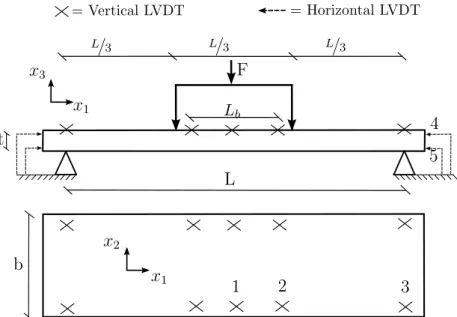
Hochreiner et al (2013) tested square 3-ply and 5-ply CLT panels with slenderness ratios of 10 and 20 and made of Norway spruce lumber boards of strength class C24 (EN 2009). The plates had their four sides supported and were submitted to concentrated loads at their center. Thanks to a combined measuring system of acoustic emission, LVDTs and accurate cutting of specimens after the failure, progressive failure stages were determined as a function of load levels (Figure 2.1). At each failure stage, the corresponding crack type identified by the panel’s cutting was assigned. The most complete documentation found in the reference paper is about the so-called specimen ”EL4”, a three-layer panel of slenderness ratio of 20. Figure 2.1 reproduces the reference test result for specimen ”EL4” in terms of its load-displacement curve, failure stages and respective failure modes. The plate showed a global ductile behavior after the elastic limit, due to its bi-axial bending configuration, whose effect is to redistribute the stresses after the first cracks appear. This ”system” effect is particularly evident in Stage 2, where the global linear behavior is not really affected by the appearance of rolling shear cracks.
0 0 20 40 60 80 100 20 40 60 80 100 120 140 160 Load [kN] Midspan deflection [mm] Failure stages Acoustic [dB] 1 2 3 4 5 6 no cracks RS, EG RS-T, TL TL, I RS-T, TL, I
Figure 2.1: Schematic load - displacement curve with identified failure stages and associated crack modes found by Hochreiner et al (2013)
All the cracking modes found during the loading process are presented in Figure 2.2. The cracks appearing first called ”RS” and ”EG” stand respectively for rolling shear failure in cross-layers and edge-gluing failure between lateral boards of the same layer. The failure mode denoted ”TL” is the tensile failure in direction parallel to grain, while ”I” is the local indentation perpendicular to grain. The failure called ”RS - T” is a complex cracking pattern occurring in cross layers at the end of the elastic limit and assumed to derive from interactions between rolling shear and tensile stresses.
Moreover, the ”RS - T” cracking pattern was also a consequence of the geometrical discontinuities appearing between boards of the same layer, after edge-gluing failure.
EG
TL
RS-T RS
I
Figure 2.2: Failure modes of specimen EL4 (Hochreiner et al 2013)
The comparison between the predicted and experimental bending response is made in terms of the panel’s global stiffness in the linear elastic load stage (stage 1 in Fig-ure 2.1) and the variation of failFig-ure modes within the apparent elastic stage (until stage 3 in Figure 2.1).
2.3
Modeling of CLT panels bending behavior
At the material scale, wood is considered as an elastic, brittle and homogeneous mate-rial. The heterogeneities characterizing the CLT layers are taken into account by means of an equivalent and homogeneous layer, whose mechanical properties are defined both in terms of elasticity and failure. Once the simplified mechanical behavior is set, the exact 3D solution in elasticity for laminated plates in bending (Pagano 1969; 1970) is chosen in order to obtain precise estimation of the plate’s mechanical response. Finally, a failure criterion suitable for wood (van der Put 1982) can point out the failure load and the corresponding dominant failure mode of CLT panels in bending.
2.3.1
Mechanical behavior of solid wood
Wood is an orthotropic material with three principal axes. The first one is aligned in the fiber or trunk direction (longitudinal direction, L). In the transverse plane, the remaining two axes are orthogonal to growth rings (radial direction, R) and tangential (tangential direction, T ) to them. Figure 2.3 presents the axes of orthotropy of solid wood.
The chosen wood species is Norway spruce (Picea abies), since it is the most widely used wood species in Europe for CLT production and was also used in the reference experiment. The mechanical properties are chosen on the basis of tests in literature on specimens of clear spruce, without knots. Table 2.1 shows the elastic and strength properties of Norway spruce taken respectively from Keunecke et al (2008) and Dahl
2.3 Modeling of CLT panels bending behavior Tangential (T) Radial (R) Longitudinal (L)
Figure 2.3: Material axes of orthotropy for solid wood
(2009). The first subscripts L, T and R represent the wood coordinate system, while the following t and c represent tensile or compressive strength. As it will be shown in the next paragraph, the failure analysis requires the complete set of nine spruce strength parameters, whose values are present only in Dahl (2009). Another exper-imental campaign on clear spruce strengths in the LT plane (Eberhardsteiner 2002) confirms the congruity of the chosen values, especially for the tensile strength. The failure behavior presented in Table 2.1 describes wood’s strength with respect only to pure uni-axial stresses. Therefore, in order to perform an exhaustive failure analysis, a mixed failure criterion for wood is required.
Elasticity EL ET ER GRL GLT GT R νLR νLT νRT
(Keunecke et al 2008) 12800 397 625 617 587 53 0.36 0.45 0.48 Failure fL,t fL,c fT ,t fT ,c fR,t fR,c fRL fLT fT R
(Dahl 2009) 63.4 28.9 2.8 3.8 4.9 3.6 7.1 4.8 2.0
Table 2.1: Elastic and strength properties of Norway spruce [MPa]
2.3.2
Van der Put’s mixed failure criterion for wood
Failure criteria define the material failure by means of normalized expressions, which represent the material’s strength surface. A stress state, that reaches or exceeds the failure surface, leads to inelastic phenomena such as damage or plastic strains. The most widely used isotropic failure criteria are based on von Mises maximum distortion energy. These criteria generally follow a quadratic expression which represents an elliptic surface. Dealing with anisotropic materials, the rotated and translated ellipsoid of Tsai-Wu (Tsai and Wu 1971) is the most common failure surface. The general quadratic expression for orthotropic materials can be written as:
f (σ) : Aσ2L+ Bσ2T + CσR2 + DσLσT + EσLσR+
+F σTσR+ GσL+ HσT + IσR+
+LτLT2 + M τLR2 + N τRT2 = 1.0
(2.1) where σ and τ are respectively the longitudinal and shear stresses in orthotropic coordinates L, T , and R. The capital letters are function of the material strengths and
they determine the geometry of the failure surface. While the coefficients of quadratic terms (A, B, C and L, M , N ) represent the semi-axes of the elliptical surface, linear (G, H, I) and interaction (D, E, F ) terms in (2.1) respectively translate and rotate the ellipsoid. The value of interaction terms in failure criteria for anisotropic materials is still nowadays under discussion. During his studies on failure criteria for wood, van der Put (1982) showed how the value of the interaction term has a negligible influence when the stress path is closed to the failure surface. Therefore, Van der Put’s failure criterion is a function f (σ) like (2.1) but without interaction terms. This failure criterion has been compared in Cabrero et al (1984) with other criteria applied to spruce failure, and it turned out to be one of the most predictive. Therefore, considering also its simple implementation due to the absence of interaction terms, Van der Put’s failure function has been chosen for the failure analysis. The coefficients of Equation 2.1 derived in (van der Put 1982) are:
A = 1 fL,tfL,c , B = 1 fT ,tfT ,c , C = 1 fR,tfR,c , D = E = F = 0 (2.2) G = 1 fL,t − 1 fL,c , H = 1 fT ,t − 1 fT ,c , I = 1 fR,t − 1 fR,c (2.3) L = 1 f2 LT , M = 1 f2 RL , N = 1 f2 T R (2.4) where wood’s strength properties fi have been discussed in Section 2.3.
If the failure criterion is proportional to the applied load, it is straightforward to find the failure load from a single linear solution. Whereas σ is already proportional to the applied load, the function f (σ) derived by van der Put (1982) turns out not to be proportional. Hence, it is necessary to derive a new function F (σ), which will describe the same failure surface, but also satisfy the condition
F (λσ) = λF (σ), λ > 0 (2.5) Property (2.5) ensures the same variation λ of F (σ), when varying the external load (and the related stress state σ) of a positive quantity λ. Rewriting the function f (σ) of Equation 2.1 leads to:
f (σ) :t(σ − k0)K(σ − k0) −tk0Kk0 = 1.0 (2.6) with σ = σL σT σR σT R σRL σLT , k0 = g h i 0 0 0 , K = A 0 0 0 0 0 0 B 0 0 0 0 0 0 C 0 0 0 0 0 0 L 0 0 0 0 0 0 M 0 0 0 0 0 0 N (2.7)
2.3 Modeling of CLT panels bending behavior
σ stands for the stresses expressed in the wood’s coordinate system, while k0 and
K include the wood’s strength properties. Developing Equation 2.6 and comparing it term to term with Equation 2.1, we can find the following components of k0:
g = fL,t− fL,c 2 , h = fT ,t− fT ,c 2 , i = fR,t− fR,c 2 (2.8)
As mentioned in Section 2.3.2, the function described by Equation 2.1 is not propor-tional to the external load. Then, we search a new function F (σ), having the property of a homogeneous function of degree one:
F (λσ) = λF (σ), λ > 0 (2.9) Substituting σ = λσ in (2.6) leads to
λ2 tσKσ − 2λ tσKk0 − 1 = 0 (2.10)
The positive root of Equation 2.10 gives the multiplier coefficient λ with which the stresses λσ produce a criterion’s value of 1.0 and consequently, the material failure. Therefore, the function
λ(σ) =
tσKk
0+p(tσKk0)2+tσKσ
tσKσ (2.11)
returns the value with which the stresses should be multiplied in order to reach the rupture. The inverse of this function F (σ) = 1/λ(σ) is a homogeneous function of degree one whose values are
(
F (σ) ≥ 1.0 if rupture occurs
0 < F (σ) < 1 if rupture does not occur (2.12) Finally, the function F (σ) = 1/λ(σ) can be derived from Equation 2.11. The value λ(σ) represents the multiplier coefficient to reach the failure point. The spatial distri-bution within the CLT panel of λ(σ) multiplied by the failure load Fc represents the
load levels necessary to reach progressive failures under linear elastic hypotheses. When the failure load is determined, it is of particular interest to establish the associated dominant failure mode. This can be achieved computing the ratios between each of the six stress components expressed in the wood’s coordinates (σL, σT, σR,
τLT, τRL, τT R) and their respective strengths (fL,c−t, fT ,c−t, fR,c−t, fLT, fRL, fT R). The
maximum value of these ratios can point out the dominant failure mode. This ratio is computed at any point within the panel.
2.3.3
Equivalent CLT Layer model
Both complete (3D) and reduced (2D or 1D) solutions for layered plates in bending consider every layer as homogeneous. In practice, each CLT layer is made of boards
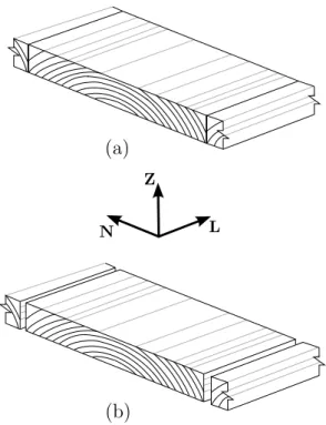
placed side by side and it is affected by the heterogeneities presented before. Hence, it is necessary to set a homogeneous ”Equivalent CLT Layer” model, which could take such heterogeneities into account. As presented before, the first complexity derives from the variation of growth rings’ orientation inside each layer, which leads to an unknown orientation of the local orthotropic coordinate system. Moreover, in case of unglued lateral boards, the resulting discontinuities influence the equivalent layer. Note that, if the lateral edges of boards were initially glued, the experimental evidence showed that the edge gluing detachment is one of the first failure modes (see Section 2.2).
N Z
L
(a)
(b)
Figure 2.4: Schematic continuous (a) and discontinuous (b) Equivalent CLT Layers together with the layer’s reference frame
2.3.3.1 Continuous Equivalent Layer
If the boards’ lateral edges are glued, each wooden layer can be viewed as a continuous layer. The same material behavior in directions N and Z of the board’s reference frame (Figure 2.4) is considered, in order to overcome the irregularity of growth rings. While the Z direction remains always the same, directions L and N change together with the orientation of the considered layer. Table 2.2 presents the elastic and strength properties of the continuous Equivalent Layer. The defined elastic moduli for the N or Z direction are the mean values between the corresponding T and R ones for solid wood (Table 2.1), while the strength parameters are the lower values.
2.3.3.2 Discontinuous Equivalent Layer
When CLT boards are not glued together on their lateral edges, or when in-plane stress caused the edge-gluing detachment, each layer becomes discontinuous (Figure 2.4b) and
2.3 Modeling of CLT panels bending behavior Elasticity EL EN EZ GZL GLN GN Z νLZ νLN νZN
12800 511 511 602 602 53 0.41 0.41 0.48 Failure fL,t fL,c fN,t fN,c fZ,t fZ,c fZL fLN fN Z
63.4 28.9 2.8 3.6 2.8 3.6 4.8 4.8 2.0
Table 2.2: Elastic and strength properties of a continuous CLT layer [MPa]
such discontinuities preclude any transmission of stresses between separated boards. This also means that failure in N -direction cannot occur. Table 2.3 shows the con-sidered mechanical behavior of an equivalent and discontinuous layer made of Norway spruce. Intuitively, due to the gaps between lateral boards, the equivalent layer’s plane shear modulus GLN may be set to zero (Mestek et al 2008). However, all layers are
glued on their upper and lower faces and hence the discontinuous CLT panel has a (re-duced) in-plane shear stiffness (Moosbrugger et al 2006). The same conclusion can be deduced for the plane shear strength of a discontinuous layer. A more accurate inves-tigation on the actual plane shear behavior of a discontinuous layer will be the object of further studies. In this first simplified approach, it is assumed that the in-plane shear behavior of layers equals the wood’s behavior. The Poisson’s ratios νLN and νZN
represent the layer’s strain in direction N , due to the imposed strain in directions L and Z, respectively. Considering layers with discontinuities along direction N as in Figure 2.4b, the values of these coefficients are assumed to be zero.
Elasticity EL EN EZ GZL GLN GN Z νLZ νLN νZN
12800 0.0 511 602 602 53 0.41 0.0 0.0 Failure fL,t fL,c fN,t fN,c fZ,t fZ,c fZL fLN fN Z
63.4 28.9 - - 2.8 3.6 4.8 4.8 2.0
Table 2.3: Elastic and strength properties of a discontinuous CLT layer [MPa]
2.3.4
Pagano’s exact solution for laminates in bending
Once the model for an equivalent and homogeneous CLT layer is set, the analytical bending solution can be chosen between complete or reduced approaches. 1D theories (Blass and Fellmoser 2004a; EN1995-1-1 2004; Kreuzinger 1999) have very low compu-tational costs but give approximate results. 2D plate theories for laminates in bending (Leb´ee and Sab 2011a; Thai et al 2013) are still reduced approaches, but return more precise results than beam theories. Nevertheless, the specimens of the reference test were submitted to concentrated loads, which produce complex stress states close to loading area, difficult to predict with reduced approaches. Therefore, the complete 3D solution from Pagano (1970; 1969) was chosen in order to obtain a precise estimation of CLT bending behavior. Pagano derived such solution for plates having homoge-neous layers and perfect connections between them under uni-axial (Pagano 1970) or bi-axial (Pagano 1969) bending configurations. The bi-axial bending solution is used
for the comparison with the reference test, while the uni-axial solution is applied to the parameter studies on CLT properties.
x3 x1 x2 L p3 ∞ u3= 0 σ11= 0 σ22= 0 u3= 0 σ11= 0 σ22= 0 x3 x1 x2 b a p3 u3= 0 u1= 0 σ22= 0 u3= 0 u2= 0 σ11= 0 u3= 0 u2= 0 σ11= 0 u3= 0 u1= 0 σ22= 0 (a) (b)
Figure 2.5: Pagano’s uni-axial (a) and bi-axial (b) bending configurations with corre-sponding applied loads and boundary conditions. u1, u2 and u3 stand for the
displace-ments in directions x1, x2 and x3 respectively
2.3.4.1 Uni-axial bending
The most common bending configuration for structural panels is represented by a plate simply supported on two sides. Pagano’s 3D solution for layered plates in uni-axial bending represents such a bending configuration. A plate under uni-uni-axial, or cylindrical, bending has only two sides supported along the same direction, while the other direction is assumed as infinite and there are no boundaries (Figure 2.5a). The displacement field is assumed to be a single Fourier-like series, like the out-of-plane load p3, acting on the plate’s upper or lower surface. In Pagano’s uni-axial bending, the
only imposed condition on the bounded edges is zero vertical displacement u3, leaving
free the in-plane displacements. 2.3.4.2 Bi-axial bending
CLT panels tested in the framework of the reference experiment were supported on their four sides, which corresponds to the bi-axial bending solution from Pagano. This solution is valid for rectangular orthotropic plates, whose axes are aligned with the axes of the supports. In this case, all the plate’s sides are simply supported (Fig-ure 2.5b) and the displacements as well as the surface load p3 are expressed as double
Fourier-like series. The boundary conditions, which make possible Pagano’s solution in bi-axial bending, consist in restraining vertical and tangential displacements at the plate’s bounded sides. As Figure 2.5b shows, the tangential displacements for edges along direction 2 and 1 are respectively u2 and u1. However, since the tangential
displacements of the reference panel’s edges were not restrained, the experiment con-figuration has more degrees of freedom than the bending solution. Further analyses not reported here showed that the reference slenderness ratio of 20 gives a difference of about 10% between the estimated deflection preventing or not edges’ tangential
2.4 Comparison with the reference test
displacements. Hence, when choosing Pagano’s bi-axial solution to reproduce the ref-erence test, it is expected to find a global stiffness about 10% higher than the refref-erence one.
2.4
Comparison with the reference test
In this Section, the predicted bending behavior is compared with the reference behavior in terms of the panel’s global stiffness and failure stages.
2.4.1
Global stiffness
Table 2.4 shows the plate’s global stiffness comparison between the reference test and each model for an equivalent CLT layer.
Continuous panel (0 - 50 kN) Global Stiffness [mmkN] measuring error Experimental reference 4.60 ± 5.0%
Predicted 5.03 (+9.3%)
-Discontinuous panel (80 - 120 kN) Global Stiffness [mmkN] measuring error Experimental reference 4.14 ± 5.0%
Predicted 4.60 (+11.1%)
-Table 2.4: Plate’s global stiffness comparison
When the lateral boards are glued to each other, the panel is continuous and its global stiffness is the slope of the load-displacement curve in the proportional limit (from 0 to 50 kN). Then, when the edge-gluing detachment occurs (≈ 80 kN), the panel presents gaps between boards and its stiffness slightly decreases. For each case, the corresponding equivalent-layer model is used to predict the CLT plate’s global stiffness. Because of the experimental uncertainty, a 5.0% margin of error in measuring the reference value of the plate’s stiffness is assumed. Taking into account the discrepancy between modeled and actual boundary conditions described in 2.3.4.2, a predicted plate’s stiffness about 10% greater than the reference stiffness is expected. Indeed, as Table 2.4 shows, for both the continuous and discontinuous case, the predicted global stiffnesses are about 10% higher than the reference stiffness. A CLT plate made of continuous layers shows higher stiffness compared to the one predicted using a discontinuous model, due to the absence in the latter of any contribution of fibers along direction N (seeTable 2.3). However, the hypotheses made on elastic properties of continuous and discontinuous CLT layers lead to a relatively small difference between their elastic response in terms of vertical displacements.
2.4.2
Failure stages comparison
In addition to the elastic panel’s deflection, Pagano’s solution can precisely estimate the stress distributions within the panel. In Section 2.3.2, the identification of failure load
and the corresponding dominant failure mode are described. A progressive increase in the load after the first failure, leads to a proportional variation of the function F (σ) within the panel. Therefore, considering simultaneously the spatial distributions of the failure criterion F (σ) and the related failure mode, leads to the derivation of failure stages under linear elastic hypothesis. A preliminary analysis revealed that, when con-sidering the plate’s cross-section, the first failures take place under the concentrated load at the plate’s center. Hence, an investigation on the variation of failure modes along the plate’s axes of symmetry is sufficient. The reference specimen is a CLT 3-ply and its failure stages were introduced in Section 2.2. For both continuous and discon-tinuous cases, the distributions of failure load are plotted for the plate’s cross-sections at x1 = a/2 and x2 = b/2 (see Figure 2.5b). This distribution highlights the load level
necessary to reach the failure along the plate cross-sections. Over such a distribution, the superimposition of the dominant failure modes points out the progressive failure stages. Table 2.5 presents the chosen abbreviations for the failure modes within a layer of a CLT panel.
Failure mode Abbreviation Tensile Longitudinal L-t Compressive Longitudinal L-c Tensile Direction-N N-t Compressive Direction-N N-c Tensile Direction-Z Z-t Compressive Direction-Z Z-c Transverse (rolling) shear ZN RS Transverse shear ZL ZL Plane shear LN LN
Table 2.5: Abbreviations of failure modes
2.4.2.1 Continuous layer
Figure 2.6a shows the distribution of failure load and failure modes within the panel’s cross section predicted with a continuous equivalent layer. For a better presentation, the ratio between the panel’s thickness and span is scaled at about 10:1. The first failure mode occurs at about 50 kN of load level. Such a failure mode is a perpendicular compressive failure close to the punching area (N-c), which is actually difficult to observe experimentally. Detailed analyses of stresses revealed how this area is affected by a tri-axial stress state. Therefore, the contribution to material failure derives from all the compression components in direction L, N and Z, with the latter as the dominant one. This is a very local phenomenon not affecting the linear response of the panel at a very short distance from the punch. Moreover, the punch, being modeled as a uniformly distributed load, cannot take into account the actual contact phenomena occurring in the experiment. The subsequent failure stage is tensile failure of the bottom layer in
2.4 Comparison with the reference test
direction N (N-t ≈ 70 kN). Such a predicted failure could explain the corresponding edge-gluing (EG) separation found in the experimental test at similar load levels (see Section 2.2) along direction N of boards. Rolling shear failure of cross layers (RS ≈ 90 kN) and longitudinal tensile failure of bottom layer (L-t ≈ 100 kN) are the next failure modes. Both of them are estimated at load levels, which slightly deviate from the experimental evidence, especially the tensile failure.
L-c N-c L-t L-t L-t L-c RS RS RS RS N-c N-t N-c L-t L-t L-c L-c L-t N-t N-c RS RS L-c x2[mm] x1[mm] Fc[kN] LZ LZ 50 70 100 140 200 ≥ 5290 270 380 530735 1020 1420 1970 2740 3800 x3 [mm] 500 1000 1500 2000 0 L-c L-t L-t L-t L-c LZ RS LZ LZ -48 -14 14 48 x3 [mm] x2[mm] x1[mm] L-c L-t L-c RS 60 RS RS LZ 85 115 160 225 ≥ 6000 Fc[kN] 315 435 605 840 1165 1625 2250 3130 4350 RS RS (a) (b) LZ LZ LZ LZ LZ -48 -14 14 48 500 1000 1500 2000 0 500 1000 1500 2000 0 500 1000 1500 2000 0 LZ
Figure 2.6: Variation of failure load and failure modes at x1= a/2 and x2 = b/2 inside
the panel predicted with the continuous (a) and discontinuous (b) models
2.4.2.2 Discontinuous layer
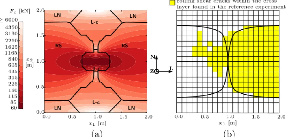
Since the first significant observed damage is the edge-gluing detachment, it is worth investigating a discontinuous equivalent layer. Figure 2.6b presents the predicted fail-ure stages for a discontinuous equivalent layer. As introduced before, the modeling of discontinuous layers prevents wood’s failure in N -direction (Figure 2.4b). Therefore, the first compressive failure close to the punching area is a contribution of only com-pression in direction L and Z, where the former is the dominant one (L-c ≈ 60 kN). Again, the modeling of wood’s mechanical behavior led to a compressive failure close to the punching area, which does not affect the plate’s global behavior. Rolling shear failure in the cross layer is the following predicted failure, with a corresponding load level (RS ≈ 80 kN) in accordance with the reference test. Moreover, the propagation of such a failure from the plate’s center to its’ edges is in agreement with the experi-mental evidence, as Figure 2.7 shows. Finally, the predicted failure stage at 120 kN is longitudinal tensile failure in the L-direction (L-t) of the bottom layer, which is in a good agreement with the reference behavior (see Figure 2.1).
rolling shear cracks within the cross layer found in the reference experiment
x1[m] 0.0 0.5 1.0 1.5 2.0 L-c L-c LN LN LN LN L-c RS RS x1[m] x2 [m] 0.0 0.5 1.0 1.5 2.0 ≥ 6000 Fc[kN] 60 85 115 160 225 315 435 605 840 1165 1625 2250 3130 4350 (a) (b) 0.0 N L Z 0.5 1.0 1.5 2.0
Figure 2.7: Horizontal section of the plate at x3 = +13mm. Failure stages predicted
with the discontinuous model (a) and the corresponding cracking pattern found in the reference experiment (b)
2.4.2.3 Discussion
Table 2.6 summarizes the predicted failure stages with continuous or discontinuous CLT layer and compares them to the experimental evidence.
Load level [kN] Failure modes
Reference test Continuous Discontinuous
50 - N-c -60 - N-c L-c 70 - N-t L-c 80 RS/EG N-t RS 90 RS/EG RS RS 100 RS/EG L-t RS 120 L-t L-t L-t
Table 2.6: Summary of predicted failure stages in comparison with the experimental evidence
As for the elastic stiffness comparison, each equivalent-layer model is in accordance within ranges of load levels, which correspond to glued or unglued lateral boards. Indeed, the continuous CLT layer gives good prediction on failure modes at low load levels, when the narrow boards are still glued. Notwithstanding the compressive inden-tation under the punch, the first predicted failure in this stage is tensile failure in the tangential direction within the bottom layer, which could cause the actual edge-gluing failure of neighboring layers found in the experiment. The discontinuous model fits well the experimental evidence at higher load levels, where the actual rise of rolling shear and tensile failures are predicted with a more accurate precision than in a continuous geometry. Finally, it appears that the edge-gluing of narrow boards makes the panel a little stiffer but, being the first failure mode, the already “damaged” discontinuous model gives better prediction of global load-carrying capacity of the panel. Therefore
2.5 Investigation on CLT panel properties
the discontinuous equivalent-layer model will be used for the parameter studies on CLT properties presented in the next section.
Like every modeling procedure, the predicted bending behavior with the present model depends on the chosen mechanical properties of raw materials. Surprisingly, elastic and strength parameters of clear spruce lead to an accurate prediction of the experimental bending behavior, even if the reference CLT panel was made of boards of strength class C24 having knots. When dealing with CLT in bending, elastic and strength responses mainly derive from either tensile or (rolling) shear effects (Mestek 2011; Hochreiner et al 2014; Czaderski et al 2007), as the previous Section 2.4.2 also shows. While rolling shear stiffness and strength are commonly assumed to be indepen-dent from the presence of defects (ETA 2013; Blass and Fellmoser 2004b;a; Blass and Gorlacher 2000; Grandvuinet and Muszynski 2016), tensile properties strongly depend on lumber strength class. Generally, dealing with C24 strength class, a mean elastic modulus value of 11.0 GPa (EN 2009) and a mean tensile strength of about 30 MPa (Stapel and van de Kuilen 2014) are assumed. Further simulations showed that when using such mean values of wood having knots, the predicted stiffness and failure stages deviate significantly from the experimental reference. In Section 2.4, a good agreement between the predicted and actual bending behavior is found using an elastic modulus of 12.8 GPa and a tensile strength of 63 MPa. This could be explained by a “system effect” when assembling lumber boards in a CLT configuration, which increases the panel stiffness and tensile strength, as also suggested by Joebstl et al (2006).
2.5
Investigation on CLT panel properties
Since the discontinuous equivalent-layer gives a good prediction of crosslam bending behavior, parametric studies with this model are carried out in order to better un-derstand CLT properties and quantify their advantages and limits. The considered bending configuration is a uni-axial bending and the out-of-plane load is an evenly distributed load. In this Section only the mechanical and deterministic behavior is considered.
2.5.1
Influence of transverse shear effects
The transverse shear weakness of CLT panels is due to the presence of cross layers and their low shear strength and stiffness. Shear effects in bending elements become more significant, while the slenderness ratio decreases. Figure 2.8 shows the failure load and mid-span deflection for a 3-ply and 5-ply CLT as a function of the plate’s slenderness ratio L/h. The total plate’s thickness h is assumed to be constant at 20cm for both 3-ply and 5-ply panels, while only the plate’s span L changes.
The slope variation of the failure load trend in Figure 2.8a points out the change of failure mode as a function of the slenderness ratio. This derives from the linear and quadratic dependency of, respectively, shear and bending failure load from the