HAL Id: hal-03022032
https://hal.archives-ouvertes.fr/hal-03022032
Submitted on 24 Nov 2020
HAL is a multi-disciplinary open access
archive for the deposit and dissemination of
sci-entific research documents, whether they are
pub-lished or not. The documents may come from
teaching and research institutions in France or
abroad, or from public or private research centers.
L’archive ouverte pluridisciplinaire HAL, est
destinée au dépôt et à la diffusion de documents
scientifiques de niveau recherche, publiés ou non,
émanant des établissements d’enseignement et de
recherche français ou étrangers, des laboratoires
publics ou privés.
Periodic walking motion of a Humanoid robot based on
human data
Anne Kalouguine, Christine Chevallereau, Sébastien Dalibard, Yannick
Aoustin
To cite this version:
Anne Kalouguine, Christine Chevallereau, Sébastien Dalibard, Yannick Aoustin. Periodic walking
motion of a Humanoid robot based on human data. EuCoMeS 2020 New Trends in Mechanism and
Machine Science. EuCoMeS 2020. Mechanisms and Machine Science, pp.349-359, 2020. �hal-03022032�
robot based on human data
Anne Kalouguine1,2, Christine Chevallereau1, S´ebastien Dalibard2
and Yannick Aoustin1
1Ecole Centrale de Nantes, Universit´e de Nantes, CNRS, LS2N, F-44000
Nantes, France, e-mail:[email protected] 2SoftBank Robotics, 43,
Rue du Colonel Pierre Avia 75015 Paris, e-mail: [email protected]
Abstract. Human walking has been intensely studied, but it is difficult to reproduce on humanoid robots that maintain awkward movements. Three main difficulties exist. (i) Di↵erent joint kinematics and size between humans and robots. (ii) A rolling motion of the foot which is often impossible to execute with humanoid robots that walk with their feet flat. (iii) A di↵erence in the dynamic model of a robot compared to a human that makes a copy of a human movement lead to unstable walking. In order to take into account the first two difficulties, the specifications for reproducing human movements are adjusted. To ensure stability, a previously developed dynamic model called Essential Model is used. The zero moment point (ZMP) is imposed, and the horizontal evolution of the centre of mass (CoM) is computed to satisfy the ZMP. Key words: Humanoid robot, Human-like walking, Center of Mass, Zero Moment point, Essential Model.
1 Introduction
Humanoid robots are complex mechatronic machines due to their numerous degrees of freedom, physical characteristics such as their weight, the limita-tions of their actuators, the unilateral constraints with the ground etc. To design walking motions is a complex challenge [1]. To overcome these difficul-ties, many researchers define the walking motions by using the linear inverted pendulum (LIP) model [2]. This model is efficient to obtain walking motions, but the resulting gait is not very human-like and the dynamic influence of the di↵erent bodies of the humanoid robot is not taken into account. Several approaches to imitate the human motion have been developed. For example a walking gait based on human-like virtual constraints has been investigated in [3] for the robot Nao. Sakka, who carried out a work about the imitation of human motion with Nao, also performed this type of study [4]. However, their approach does not consider the constraints on the ZMP trajectory, which are essential for stability.
The purpose of this work is to design a periodic walking motion with single support (SS) and double support (DS) phases, which is based on the Essential model [5] for Romeo - a humanoid robot with n = 31 generalized coordinates. The trajectory of the ZMP is imposed, the horizontal position of the CoM is free to adapt to the ZMP evolution. The CoM is thus computed from this ZMP evolution. The original contribution is that the remaining n 2 generalized coordinates are prescribed by using trajectories inspired from human walking data. The recorded human motions are approximated by sinusoidal functions of time.
The paper is outlined as follows. The main characteristics of human walk-ing are presented in section 2. A reference walking motion based on human data is presented in section3. This section highlights the necessity of the Es-sential model, which is then detailed in section4. The cyclic walking motion is stated in section 5. Numerical results are analyzed in section 6. Section8
o↵ers our conclusions and perspectives.
2 Study of human walking.
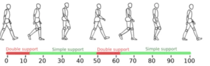
Duration of di↵erent phases: Human walking can be decomposed accord-ing to important events that occur duraccord-ing the walkaccord-ing. A gait cycle consists of two steps. The duration of di↵erent phases is measured as a percentage of a cycle duration. The percentage of DS phase varies from 9 to 17% depending on the age and velocity of the human [6].
Fig. 1 SS and DS phases duration, measured as percentage of complete cycle.
Step placement: The step length and width vary widely depending on mor-phology and age. For a young healthy adult the step length varies widely (from 0.40 to 0.80m for larger velocities), same as the step width (from 0.125 to 0.22m, with width decreasing for larger velocities) [6, 7].
CoM Trajectory: Human CoM trajectory is close to a sinus in longitudinal, transverse and vertical directions [6]. The magnitude and period of oscil-lations in transverse direction vary with speed [8]. In vertical direction the magnitude of the oscillations increases with velocity and is equal to about 2% of body height.
ZMP trajectory: The ZMP (Zero Moment Point) goes from the heel to the tip of each foot [9], which corresponds to the rolling motion of the feet and the mobility of the human sole. The trajectory of the ZMP changes depending on the footwear of the human [10].
Swing foot motion: The motion of the swing foot can be separated in two components, the trajectory of the swing foot as a whole and the orientation of the sole. We observe nearly vertical landing and takeo↵ trajectories, with most of the horizontal movement performed in the middle of SS.
Trunk motion: The trunk, which represents 60% of the weight, has signif-icant angular oscillations[11]: in the saggital plane, the amplitude is of about 2 around the equilibrium position (which varies with the walk-ing velocity but is typically between 5 and 13 , leanwalk-ing forward). In the frontal plane, the oscillations amplitude varies from 3 to 6 depending on the velocity.
Hip motion: The oscillations of the hip and the basin allow to make big-ger steps, to smoothen the trajectory of the CoM. The amplitude of the oscillations around the vertical axis is of about 10 [6].
Arm swing: The arm swing in human locomotion is speculated to be useful to reduce the contact wrench on the support foot, as well as the global cost of walking [12], [13].
.
3 Human trajectory and humanoid robot
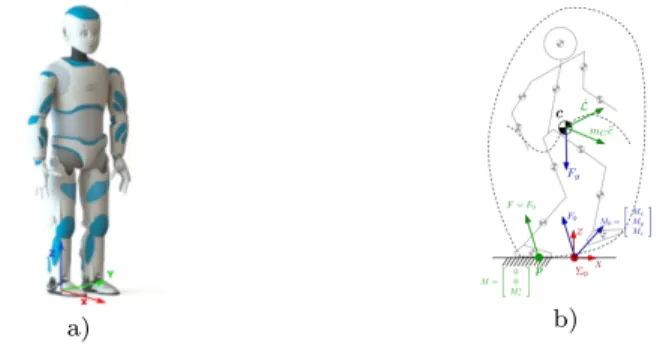
Once the human trajectories are found, they can be applied to a humanoid robot. However, that does not give a viable walking motion. Romeo is a prototype platform issued by company Softbank Robotics, see figure3a). It is 1m47 tall, weighs 36 kg and features 31 degrees of freedom groups into the configuration vector q. The duration of the DS phase is chosen to be close to 12% of the cycle duration 2· T , where T = TDS + TSS, TDS = 0.15s and
TSS = 0.60s are the durations of the DS phase and SS phases. It is impossible
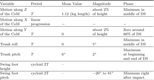
to achieve a step size of 0.75m as what is observed for humans, because the pelvic rotation and rolling motion of the stance foot is necessary for these larger steps, see [14]. It is necessary to adapt the parameters of trajectories for Romeo. The step width is chosen to be 0.20 m to satisfy a safe clearance between Romeo’s ankles. The step length is chosen in the range 0.15 to 0.20 m, which corresponds to a 0.30-0.40 m displacement of the swing foot and a velocity of 0.83 to 1.1 km/h. A summary of the other adaptations is shown in the following table1. We approximate most periodic functions by a sinus to have a simple model that is infinitely di↵erentiable.
Once we have adapted the human walking motion to the n = 31 variables of Romeo, we tried to run it on the robot model. Due to di↵erences in dy-namics, the ZMP position resulting from these trajectories will not satisfy
Table 1 Main parameters of the trajectories for Romeo Variable Period Mean Value Magnitude Phase
Motion along Z about 2% Minimum in
of the CoM T 1.12 (leg length) of height middle of DS Motion along X linear
of the CoM progression
Motion along Y about 2% Zero around
of the CoM T 0 of height 80% of DS
Minimum in
Trunk roll T 0 5 middle of DS
Maximum
Trunk pitch T 6 2 at beginning
and end of DS Swing foot cycloid 2T –
height
Swing foot cycloid 2T – 20 to 81 Minimum right
pitch after impact.
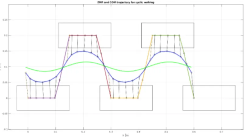
the equilibrium condition. We checked that the ZMP trajectory is outside the support polygon, as is visible in figure2
Fig. 2 ZMP (multicolored) obtained if the human COM motion (in green) is applied to the robot Romeo.
To solve this problem, we need to impose the ZMP trajectory instead of the CoM by using the Essential model first introduced in [5].
4 Essential model
Instead of imposing as many trajectories as there are degrees of freedom (DoFs), we will leave two DoFs to allow for a better placement of the ZMP.
Since the relation between ZMP and CoM is considered as a determining feature of human gait [2,15], and the positions of CoM and ZMP are strongly linked, we choose to ”set free” the horizontal coordinates rf = (x, y) of CoM
in order to adapt to the imposed trajectory of the ZMP.
To take inspiration from the human motion, let us introduce r 2 R31⇥1:
r = (rf, rc)>= (x, y, z(t), xf(t), yf(t), zf(t), f(t),
✓f(t), f(t), tr(t), ✓tr(t), tr(t), q13(t),· · · , q31(t))>.
(1)
We define rc as the vector of the 29 variables of r for which the trajectories
are imposed. z(t) defines the desired altitude of the CoM. xf(t), yf(t), zf(t)
and f(t), ✓f(t), f(t) describe the desired position and desired orientation
of the free foot, and ( tr, ✓tr, tr) give the desired orientation of the torso
link. The upper-body variable joints are defined by q13 to q31. The desired
motion for rc(t) is defined based on human motion as summarized in table1.
The robot configuration can be defined by the vector q or r and a geometric model can be built. Let q = g(rf, rc), ˙q and ¨q are deduced thanks to the
kinematic models as follows:
˙q = Jf˙rf+ Jc˙rc, q = J¨ fr¨f+ ˙Jf˙r2f+ Jcr¨c+ ˙Jc˙rc2. (2)
Here Jf 2 R31⇥2 and Jc 2 R31⇥29. In the current study the evolution of rc
is chosen as a function of time, thus the joint evolution can be expressed as function of rf, ˙rf, ¨rf and t only :
q = gt(rf, t), ˙q = Jf˙rf+ v(t, rf), q = J¨ fr¨f+ ˙Jf˙rf2+ a(t, rf, ˙rf). (3)
a) b)
Fig. 3 a) Photography of Romeo. b) Illustration of the global equilibrium.
To evaluate the feasibility of a walking trajectory, it is necessary to cal-culate the e↵ects of external forces acting on the humanoid robots. The origins of these external forces are the gravity force Fg and the ground
ef-fect of the ground reaction is defined by the wrench 2 R6⇥1 (F
0, M0)> =
(Fx, Fy, Fz, Mx, My, Mz)> in a reference frame ⌃0. The global equilibrium of
the robot can be written as : ✓ F0 M0 ◆ = ✓ AF AM ◆ ¨ q + ✓ dF(q, ˙q) dM(q, ˙q) ◆ (4)
where q 2 R31⇥1 is the joint vector of the robot.
Using equation (3), the global equilibrium (4) can be rewritten: ✓ F0 M0 ◆ = ✓ AF r(t, rf) AM r(t, rf) ◆ ¨ rf+ ✓ dF r(t, rf, ˙rf) dM r(t, rf, ˙rf) ◆ (5)
Let p = (px, py, 0)> be the global zero moment point (ZMP). Its coordinates
pxand py satisfy :
Fzpx+ My= 0, Fzpy Mx= 0. (6)
(px, py) must be inside the convex hull of support for all times in order to
satisfy the dynamic equilibrium condition [16]. To be sure to find a periodic motion that satisfies the equilibrium condition, we choose a desired evolution (px(t), py(t)) of the ZMP. During the SS phase the desired motion of the
ZMP is a function of time to define a migration of the ZMP from the heel to the toe of the stance foot. In DS phase the desired motion of the ZMP is defined by a linear evolution form the final position of the ZMP at the end of the SS phase on the stance foot, until the initial position of the ZMP at the beginning of the SS on the next stance foot. Using equation (6), and using the 3th, 4thand 5thlines of (5), we obtain :
(AF rz(t, rf)¨rf+ dF rz(t, rf, ˙rf)) px(t) + AM ry(t, rf)¨rf+ dM ry(t, rf, ˙rf) = 0
(AF rz(t, rf)¨rf+ dF rz(t, rf, ˙rf)) px(t) AM rx(t, rf)¨rf dM rx(t, rf, ˙rf) = 0
(7) that isolates the essential characteristic of the walking that is the rela-tionship between the ZMP and the CoM. Solving of equation (7) gives the Essential model describing the acceleration of the horizontal positions x and y of the CoM, that are defined to achieve to an imposed evolution of the ZMP:
¨
rf = f (rf, ˙rf, t, px(t), py(t)). (8)
By integration of (8) from initial conditions we can calculate the current values of ˙rf, i.e ˙x, ˙y, and rf, i.e x, and y. To sum up, the evolution of x and
y is not imposed in order to allow them to adapt to the imposed evolution of the ZMP. With this strategy to define a reference trajectory of walking, which is based on the Essential model (8) and rc(t), no approximations are made
to the dynamic model when designing the humanoid walking. The method ensures the feasibility of a walking trajectory from the point of view of the condition on the ZMP. The choice of z(t) of the CoM allows to satisfy the
positivity of the vertical component of the resultant ground reaction force during the walking. The condition of no slipping can be checked based on the knowledge of ¨rf and ¨z.
Then the torques required to produce the motion have to be calculated. During the SS phase, considering the stance foot motionless on the ground, we can define the dynamic behavior of the robot:
⌧ = Ar(t, rf)¨rf + dr(t, rf, ˙rf) (9) In DS phase e↵ort ✓ Fext Mext ◆
are applied on the second leg, (9) becomes
⌧ = Ar(t, rf)¨rf + dr(t, rf, ˙rf) + Jext ✓ Fext Mext ◆ . (10)
The global equation gives the global reaction force F0, M0, but the
distribu-tion on both legs is free and will modify the actuadistribu-tion torque. During double support, the global ZMP is the barycentre of the two local ZMPs on each foot, this implies that the global ZMP and the local ZMPs are aligned. The evolution of the global ZMP is chosen in order that during all the DS, the two local ZMPs keep a constant pose corresponding to the final pose of the ZMP in SS : p5, and the initial pose of the ZMP for the next SS : p2. We can
calculate the vertical reaction force on leg 1 and 2 F1z and F2z by solving
this system: p1xF1z+ p2xF2z F1z+ F2z = px p1yF1z+ p2yF2z F1z+ F2z = py (11)
To avoid slipping, the ratio between tangential and normal force for the global equilibrium is conserved for each leg. The components F1x, F1y, F2x, and F2y
are calculated to satisfy: F1x F1z = F2x F2z = F1x+ F2x F1z+ F2z F1y F1z = F2y F2z = F1y+ F2y F1z+ F2z (12)
By using (11) and (12) we find Mz = M1z+ M2z. The moment around the
z axis is also share between the two legs using a similarly distribution to the force components (12) as follows:
M1z F1z =M2z F2z =M1z+ M2z F1z+ F2z (13)
5 Periodic walking
The target walking motion is periodic, with a step that is composed of SS phase and a DS phase. There is no impact at the end of the SS phase. To find the walking motion a boundary problem is solved as fol-lows. The algorithm starts from an initial guess of CoM position and ve-locity (x(t0), y(t0), ˙x(t0), ˙y(t0)) at the start of DS phase. The condition for
periodicity is
(x(t0), y(t0), ˙x(t0), ˙y(t0)) = (x(t0+ T ), y(t0+ T ), ˙x(t0+ T ), ˙y(t0+ T )) (14)
tacking into account the change of the reference frame when the two legs switch their role just after the end of the current step. So ˙x(t0+ T ), ˙y(t0+ T )
are the initial velocities of the CoM in DS of the next step. The boundary value problem is, what are x(t0), y(t0), ˙x(t0) and ˙y(t0) such that after
inte-gration of (8) over the time interval [t0, t0+ T ] the cyclic condition (14) is
satisfied.
6 Numerical results
We obtained a cyclic trajectory for a step size of 0.15 m, all other parameters being the same as described in table1. A stick-diagram over one cycle of this cyclic walking motion is presented figure4.
Fig. 4 Obtained COM trajectory (in blue) for the imposed human-like ZMP trajec-tory (multicolored), compared to a typical human COM trajectrajec-tory (in green).
Fig. 5 Stick-diagram of a walking.
We observe on figure 4 that the COM trajectory is oscillating in the Y direction a lot more than what is typical for human walking. This di↵erence can be explained by the slightly larger step width (necessary because of geo-metric constraints on Romeo) and the overall slower walking velocity. Indeed, the slower the walking gait, the closer it gets to semi static, and the larger the COM oscillations in Y direction [7].
This result can be compared to the ”raw” ZMP trajectory based on a human-like COM trajectory without constraints on the ZMP, as presented on figure2. It is obvious that this trajectory would not be viable, as the ZMP trajectory is outside of the convex hull of the foot during single support phase. This proves the relevance of the approach used with the Essential Model, imposing constraints on the ZMP position rather than COM allows to achieve a dynamically stable walking motion.
7 E↵ect of ZMP evolution on torques
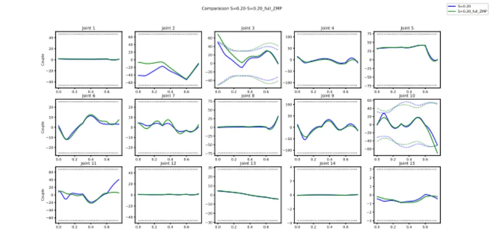
The results presented above correspond to an evolution of the ZMP going from the heel to the tip of each foot (see figure 4). The torque at the ankle is directly a↵ected by the pose of the ZMP. It can be seen in figure 6 (2nd
image), that the propulsive torque is low at the beginning of the step. As a consequence, a high propulsive torque is required at the knee joint (figure6
(3thimage). In fact this high torque exceeds the limits of the actuator (shown
in dotted line) of the robot Romeo. We explored the e↵ect of the influence of ZMP evolution. The results show that a modification of the ZMP trajectory influences the torques in the support knee and in the support ankle. A ZMP that has a constant position in front of the foot allows a higher propulsive force at the beginning of the SS, and thus allows to decrease the propulsive
force at knee, and then produce a knee torque compatible with the actuator of Romeo.
Fig. 6 Joint torques (N.m) versus time (s): comparison of the torque in the lower part of the robot for two cyclic trajectories with a step size of 0.20 m and a period of 0.75 s. The trajectory in green is with a human like ZMP evolution in DS, and the trajectory in blue has a ZMP constrained to the front of the foot.
8 Conclusions
We developed a 3D cyclic walking motion for a humanoid robot, Romeo. Each step is composed of a SS phase and a DS phase. The design is based on the use of the Essential model that ensures the feasibility of the motion by satis-fying the ZMP condition, which is the hardest constraint to meet. The other generalized variables of the robot are defined as smooth periodic functions of time taking inspiration from human walking motions. A dynamic model and the global equilibrium of the robot prove that the obtained walking motions are valid. The perspectives are to complete the cyclic walking motions with a starting phase and a stopping phase and to test a set of walking motions with an experimental platform.
References
1. D. Tlalolini, Y. Aoustin, and C. Chevallereau, “Design of a walking cyclic gait with single support phases and impacts for the locomotor system of a thirteen-link 3d biped using the parametric optimization,” Multibody System Dynamics, vol. 23, no. 1, pp. 33–56, 2010.
2. S. Kajita, H. Hirukawa, K. Harada, and K. Yokoi, Introduction to humanoid robotics. Springer, 2014, vol. 101.
3. A. D. Ames, E. A. Cousineau, and M. J. Powell, “Dynamically stable bipedal robotic walking with nao via human-inspired hybrid zero dynamics,” in Proc. of the 15th ACM int. conf. on Hybrid Systems: Computation and Control. ACM, 2012, pp. 135–144.
4. S. Sakka, Imitation des mouvements humains par un robot humano¨ıde sous con-trainte d’´equilibre. HDR, Universit´e Pierre et Marie Curie (UPMC), 2017. 5. V. De-Le´on-G´omez, Q. Luo, A. Kalouguine, J. A. P´amanes, Y. Aoustin, and
C. Chevallereau, “An essential model for generating walking motions for hu-manoid robots,” Robotics and Autonomous Systems, vol. 112, pp. 229–243, 2019. 6. J. Rose and J. G. Gamble, Human walking, 3rd ed. Williams & Wilkins, 2006. 7. M. S. Orendur↵, A. D. Segal, G. K. Klute, J. S. Berge, E. S. Rohr, and N. J. Kadel, “The e↵ect of walking speed on center of mass displacement.” Journal of Rehabilitation Research & Development, vol. 41, no. 6, 2004.
8. T. Jurcevic Lulic and O. Muftic, “Trajectory of the human body mass centre during walking at di↵erent speed,” in DS 30: Proc. of DESIGN 2002, the 7th Int. Design Conf., Dubrovnik, 2002.
9. M. Grundy, P. Tosh, R. McLeish, and L. Smidt, “An investigation of the centres of pressure under the foot while walking,” J. of bone and joint surgery. British volume, vol. 57, no. 1, pp. 98–103, 1975.
10. P. Sardain and G. Bessonnet, “Zero moment point-measurements from a hu-man walker wearing robot feet as shoes,” IEEE Trans. on Systems, Man, and Cybernetics-Part A: Systems and Humans, vol. 34, no. 5, pp. 638–648, 2004. 11. A. Thorstensson, J. Nilsson, H. Carlson, and M. R. ZOMLEFER, “Trunk
move-ments in human locomotion,” Acta Physiologica Scandinavica, vol. 121, no. 1, pp. 9–22, 1984.
12. P. Meyns, S. M. Bruijn, and J. Duysens, “The how and why of arm swing during human walking,” Gait & posture, vol. 38, no. 4, pp. 555–562, 2013.
13. Y. Aoustin and A. M. Formalskii, “3d walking biped: optimal swing of the arms,” Multibody System Dynamics, vol. 32, no. 1, DOI 10.1007/s11044-013-9378-3, pp. 55–66, 2014.
14. K. T., C. Chevallereau, and A. Y., “E↵ect of circular arc feet on a control law for a biped,” Robotica, vol. 27, no. 4, pp. 621–632, 2008.
15. T. Koolen, T. de Boer, J. Rebula, A. Goswami, and J. Pratt, “Capturability-based analysis and control of legged locomotion, part 1: Theory and application to three simple gait models,” Int. J. of Robotics Research, vol. 31, no. 09, pp. 1094–1113, 2012.
16. M. Vukobratovic and B. Borovac, “Zero-moment point-thirty five years of its life,” Int. J. of Humanoid Robotics, vol. 1, no. 1, pp. 157–173, 2004.