HAL Id: hal-01427504
https://hal-lara.archives-ouvertes.fr/hal-01427504
Submitted on 5 Jan 2017
HAL is a multi-disciplinary open access
archive for the deposit and dissemination of
sci-entific research documents, whether they are
pub-lished or not. The documents may come from
teaching and research institutions in France or
abroad, or from public or private research centers.
L’archive ouverte pluridisciplinaire HAL, est
destinée au dépôt et à la diffusion de documents
scientifiques de niveau recherche, publiés ou non,
émanant des établissements d’enseignement et de
recherche français ou étrangers, des laboratoires
publics ou privés.
function
James Baudoin, Jean-Paul Bello
To cite this version:
James Baudoin, Jean-Paul Bello. Approaching standard by designing a basic safety function .
[Re-search Report] Notes scientifiques et techniques NS 315, Institut National de Recherche et de Sécurité
(INRS). 2014, 56p. �hal-01427504�
NS 315
Approaching standard
EN ISO 13849-1 by designing
a basic safety function
Approaching standard
EN ISO 13849-1 by designing
a basic safety function
James Baudoin
Jean-Paul Bello
INRS, Work Equipment Engineering Department
Safety of Automated Systems Laboratory
NS 315
This document is intended to guide designers to perform machinery control systems with only one or a few "basic" safety functions such as emergency stop or movable guard.
Among the available standards for machine design, EN ISO 13849-1 is the one providing recommendations to design safety related parts of control systems (SRP/CS) implementing different types of energy such as electric, hydraulic or pneumatic.
This document is based on the implementation of the simplified method of EN ISO 13849-1 and helps to understand the new concepts introduced by this standard.
The first part of the document entitled: Design guide for a SRP/CS, sheds light on some parts of the standard and also provides tools (graphs, tables ...) to facilitate the understanding and use but also choices that designers will have to do.
The second part consists of a practical case of a safety function designed by INRS using the standard and the tools shown in the guide. All phases of design are discussed, highlighting details and comments deemed necessary to assimilate the principles advocated by the standard.
Although new, the standard EN ISO 13849-1 does not bring major changes in the design of control systems related to safety. It retains much of the design principles recommended in the standard EN 954-1 that it replaces. The main new of this framework lies in the quantification of a number of parameters.
TABLE OF CONTENTS
FOREWORD ... 3
GUIDE TO DESIGNING AN SRP/CS ... 4
1 INTRODUCTION ... 4
2 SPECIFICATION OF A SAFETY FUNCTION ... 4
3 DETERMINATION OF THE REQUIRED PERFORMANCE LEVEL ... 4
4 GENERAL DESIGN PROCESS FOR A SF/CS ... 5
4.1 General logical structure model for a SF/CS ... 5
4.2 Graph of the general design process for a SF/CS conforming to a required PL... 5
4.3 Specifications of an SRP/CS ... 9
5 COMBINING SRP/CS OF KNOWN PL ... 9
6 DETAILS OF DESIGNING AN SRP/CS... 9
6.1 Principle ... 9
6.2 Recommendations for selecting the most appropriate minimal requirements when designing an SRP/CS ... 9
6.3 Steps in designing an SRP/CS ... 11
6.4 Taking systematic failures into account ... 13
6.5 Requirements to assess measures to prevent common cause failures (CCF) ... 13
6.6 Application of the "block method" ... 14
6.7 Diagnostic coverage (DC) of dangerous failures ... 14
6.8 Calculating MTTFd for pneumatic, mechanical and electromechanical components (Annex C of the standard) .. ... 16
7 COMBINING SEVERAL FUNCTIONS TRIGGERING THE SAME ACTUATOR ... 17
8 NOTES ON THE USE OF SISTEMA SOFTWARE ... 18
ANNEX 1:TABLES OF MINIMAL RECOMMENDATIONS TO ACHIEVE A GIVEN PL ... 20
EXAMPLE OF DESIGN OF A SF/CS OF PLR "D" - CATEGORY 3 ... 25
A1. PRESENTATION OF THE FUNCTION ... 25
A2. SPECIFYING THE SAFETY FUNCTION... 26
A3. BASIC LOGICAL STRUCTURE ... 27
A4. DEFINITION OF THE NECESSARY SRP/CS TO CREATE THE SF/CS "STOP OF HYDRAULIC MOTOR BY THE GUARD" ... 28
A5. DESIGNING THE SRP/CS ... 29
A5.1 Design of SRP/CSa ... 29
A5.2 Design of SRP/CSb ... 38
A5.3 Design of SRP/CSc... 41
A6. FINAL RESULTS FOR THE SF/CS ... 50
A6.1 Determination of the PL for the SF/CS ... 50
A6.2 Reaction time for the SF/CS ... 50
A6.3 Final diagram of the SF/CS ... 51
Foreword
During the design of working equipment, such as a machine, it is necessary to take its "control system" into account. The control system is designed to ensure that the equipment functions as expected. When safety functions are necessary, the control system must also treat them to reduce the risks related to using the equipment, both for operators and exposed third parties.
Among the available reference texts for machine design, standard EN ISO 13849-11 can be used to develop control systems relying on various types of energy, including electric, hydraulic and pneumatic. This standard describes the general principles for the design of safety-related parts of control systems (SRP/CS).
EN ISO 13849-1 replaces standard EN 954-12 which was widely used in industry, but is no longer valid.
The new standard does not make many significant changes to the design of control systems with regards to safety as it retains the majority of the design principles recommended in standard EN 954-1. For example, the designer must continue to implement:
- components appropriate for the function for which they are destined, - components designed according to proven safety principles,
- single- or double-channel architectures (redundancy),
- where necessary, diagnostic procedures to test the components (self-checking), - means to avoid systematic failures.
The main novelty in this reference text is the quantification of a certain number of parameters, including:
- calculation of the MTTFd (Mean Time To dangerous Failure) from data relating to reliability and
solicitation of the components implemented,
- quantification of the measures to ensure diagnostic coverage for the components, - quantification of measures to avoid common cause failures.
Contrary to what might be expected, these calculations are straightforward and limited if the simplified procedure described in the standard is used, and particularly when the safety functions to be designed are simple and involve few components, or when the selected components have known performance levels.
In the case of more complex applications, a software tool is freely available: SISTEMA. It assists the designer in applying EN ISO 13849-1 by taking them through the different design phases recommended by the standard and by calculating the necessary data without requiring external recourse to the formulae.
This document aims to guide SRP/CS designers in the use of the standard and to help them understand the new ideas that it introduces. It is based on a practical case treated by INRS.
Warning 1
This document is in no case a substitute for the standard which should be read first and used throughout the design process. This is important as not all of the recommendations from the standard are mentioned here.
Note: In the remainder of this document, all references (paragraph, table, etc.), unless specified, refer to the present document.
1
EN ISO 13849-1: 2008: Safety of machinery. Safety-related parts of control systems - Part 1: General principles for design (called "the standard" in the document)
Guide to designing an SRP/CS
1
Introduction
This document is intended as a guide to designers developing SRP/CS, it is based on the simplified method described in EN ISO 13849-1 (see § 4.5.4 of the standard), but does not address the related software (§ 4.6 and Annex J of the standard), or the validation phase (§ 8 of the standard, which refers to standard EN ISO 13849-23 in particular).
The system controlling the safety features of a machine is composed of one or more safety functions. A specific part of the control system is dedicated to each safety function. To facilitate reading, this is abbreviated as (SF/CS4 in the remainder of this guide).
Each SF/CS includes at least one material part (SRP/CS) and may also include a software part. A SF/CS must conform to a defined performance level appropriate for the safety function it performs.
2
Specification of a safety function
The first step in designing a SF/CS is to precisely define the safety function that it will perform, in particular by describing the following:
- its required safety performance level, PLr (see § 3),
- its activation conditions, such as the operating modes in which the function is active/inactive, - how it works, describing the expected action, as a function of the input information,
- its level of priority relative to other simultaneous functions, - its maximum reaction time,
- Its frequency of solicitation, - environmental conditions, - etc.
3
Determination of the required performance level
A SF/CS must perform to a certain level to be able to ensure the safety function it is designed to control. In EN ISO 13849-1, the capacity of a SF/CS to perform a safety function is expressed by determining its performance level (PL). The standard defines 5 possible performance levels for a control system, from PL "a" to PL "e" (see Figure 2). Before designing a SF/CS, it is essential to determine the required performance level (PLr) for the
safety function. The PL achieved by the SF/CS must be at least equal to the PLr for this safety function. The PLr
3 EN ISO 13849-2: 2008: Safety of machinery. Safety-related parts of control systems – Part 2: Validation 4 SF/CS: Control System of the Safety Function (this abbreviation is not standardised).
Figure 1: Sample structure of a safety-related control system of a machine
Presentation of the basic
design of a safety-related
control system
SF1/CS SRP/CSa SRP/CSb SRP/CSc SF2/CS SRP/CSd SRP/CSedepends on how much the safety function contributes to risk reduction, which is determined based on an estimation of this risk. Annex A of the standard provides a method to determine the PLr.
The PLr for each SRP/CS composing a SF/CS must be at least equal to the PLr of this SF/CS.
For each performance level, the standard provides an equivalent average probability of dangerous failure per hour (PFHd) for the control system (Table 3 of the standard). A failure is termed dangerous when it could lead
to a potentially dangerous situation.
4
General design process for a SF/CS
4.1 General logical structure model for a SF/CS
A SF/CS generally includes several logical entities to treat the input orders and to control pre-actuators through a Logic unit. Figure 3 represents the most common construction, composed of three elements.
The designer can choose to develop these logical entities as one or more SRP/CS depending on the material he/she expects to use. This development can be done in different ways, as illustrated in paragraph 4.2.
4.2 Graph of the general design process for a SF/CS conforming to a required PL Graph 1 illustrates:
- various design pathways suggested by EN ISO 13849. The designer's choice is determined by the commercially available components, by the specific design practices for each company, by the complexity of the SF/CS to be developed, by the technology behind the components used, etc. - various means to determine the performance level "PL" achieved by a SF/CS, and to compare it to
the required PL.
High risk
Low risk
PLa
10-4 > PFHd ≥ 10-5PLb
10-5 > PFHd ≥ 3x10⁻⁶PLc
3x10⁻⁶ > PFHd ≥10-6PLd
10-6 > PFHd ≥ 10-7PLe
10-7 > PFHd ≥ 10-8 Figure 2Input
Logic
Output
Information acquired from various safety captors
Logic required to perform the safety function
Commands sent to pre-actuators
Graph 1: General design process for a SF/CS conforming to a required PL
Define each logical entity in detail and associate each entity with
one or more SRP/CS of known PL (e.g. one or more commercially available safety modules) and/or with one or more SRP/CS to be designed Examples of combinations of SRP/CS that can be used to develop the SF/CS (§ 4.4 of the standard)
Target: the required PL for the SF/CS
Develop a basic logical structure for the SF/CS – Example:
Determine the PL for the SRP/CS and deduce that of the CS/SF
Determine the PL of the SF/CS using Table 11 of the Standard
PL SF/CS ≥ PLr
No
No
Design of the SF/CS completed
Input Logic Output
Design the SRP/CS using the
simplified procedure - See Graph 2
Combining SRP/CS of known PL (≥ PLr) and SRP/CS to be designed, examples below
OR Input Logic Output SRP/CS to be designed PL?? Input/Logic PL??
Determine the PL for each of the SRP/CS designed
Design the SRP/CS of unknown PL using the simplified
procedure – See Graph 2
For each SRP/CS PL ≥ PLr SRP/CS of known PL (≥ PLr) Input PLx ≥ PLr Logic PLy ≥ PLr Output PLz ≥ PLr Input/Logic PLx ≥ PLr Input PLx ≥ PLr Output PLx ≥ PLr PL?? Output Logic/output PL?? OR OR Input PL?? Logic PLy ≥ PLr Output PL?? SRP/CS PLx ≥ PLr SRP/CS PLx ≥ PLr
Graph 1 shows that the designer of a control system has three options:
- In the left branch, he/she only combines SRP/CS of known PL (data provided by the manufacturer) greater than or equal to the required PL for the SF/CS (represented in blue). Examples are: a commercially available safety logic unit, a light curtain, etc. (example Figure 4
)
. The PL of the SF/CS is determined by applying paragraph 6.3 of the standard, in particular Table 11 (Take Warning 2 of this document into account).- In the central branch, a mixed solution is illustrated. The designer combines one or more SRP/CS of known PL, greater than or equal to the required PL for the SF/CS (represented in blue) and one or more SRP/CS of his/her own design (represented in green), an example is given in Figure 5. The steps in designing an SRP/CS are presented in Graph 2: Details of the design of an SRP/CS to achieve a required PL .
The PL of the SF/CS is determined by applying paragraph 6.3 of the standard, in particular Table 11 (Take Warning 2 of this document into account).
Figure 4: Example of a SF/CS composed of 3 SRP/CS of known PL Fail-safe
double valve To actuator
SRP/CS of known PL
SRP/CS to be designed
Figure 5: Example of an SF/CS combining SRP/CS of known PL with an SRP/CS to be designed
Light Curtain
SRP/CS of known PL
Safety logic unit (category 3 or 4) SRP/CS of known PL Light Curtain SRP/CS of known PL
Safety logic unit (category 3 or 4) SRP/CS of known PL Return loop Power cut-off chains
- In the right-hand branch, the designer uses a single SRP/CS of his/her own design (represented in green) (see Figure 6
)
.This could, for example, involve assembling basic components, such as position switches, proximity sensors and electromechanical relays.
The steps in designing a SRP/CS are presented in Graph 2: Details of the design of an SRP/CS to achieve a required PL.
Warning 2
Combining several SRP/CS within a single SF/CS
When combining several SRP/CS in series5, the PL achieved by each one must be determined. The PL of the SF/CS as a whole will depend on that of the SRP/CS it is composed of. It will thus be:
- Equal to the lowest PL for the different SRP/CS if only one SRP/CS has achieved this PL. Example
- Lower than or equal to the lowest PL, depending on the number of SRP/CS having achieved this PL. Table 11 in the standard indicates the overall PL as a function of the number of SRP/CS with the lowest PL.
In the following example, the lowest PL is "PLe". If more than three SRP/CS have a PLe, Table 11 of the standard indicates that the PL of the SF/CS is "PLd".
5
In series: implementation of several SRP/CS such that failure of any single SRP/CS leads to failure of the whole CS/SF
SF/CS with PLa
SRP/Cs1
PLa
SRP/Cs2
PLb
SRP/Cs3
PLe
SF/CS with PLd
SRP/Cs1
PLe
SRP/Cs2
PLe
SRP/Cs3
PLe
SRP/Cs4
PLe
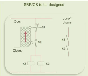
Figure 6: Example of a SF/CS composed of a single SRP/CS to be designedcut-off chains Open
Closed
4.3 Specifications of an SRP/CS
Depending on the design strategy selected, each of the SRP/CS making up the SF/CS will either be chosen "off the shelf", or specifically designed. In either case, it is necessary to specify, based on the specifications of the SF/CS in which it will be integrated (see paragraph 2), the function the SRP/CS is to perform, in particular by determining:
- its required PL, which should be at least equal to the PLr of the SF/CS,
- its activation conditions, such as the operating modes in which the SRP/CS is active/inactive, - how it works, describing the expected action, as a function of the input information,
- its interaction with the other SRP/CS making up the SF/CS, - its level of priority relative to other simultaneous functions, - its maximum reaction time,
- how often it will be solicited (which can differ for the SF/CS), - environmental conditions,
- etc.
Note: when a SF/CS consists of a single SRP/CS, the specifications for the SRP/CS are identical to those of the safety function and there is no need to formulate a new specification.
5
Combining SRP/CS of known PL
When a SF/CS is produced by combining (e.g. Figure 4) or integrating (e.g. Figure 5) SPR/CS of known PL, it is also necessary to implement measures to avoid systematic failures. This mainly means conforming to the instructions relating to the various components and to inter-component connections (see the example in Figure 17, paragraph A5.2).
6
Details of designing an SRP/CS
6.1 Principle
For each SRP/CS to be designed, the designer's will aim to implement the measures necessary to achieve a performance level at least equal to the PLr for the SF/CS. To do this, it is essential to consider the following
criteria, which are listed in § 4.5.1 of the standard: - the structure (see Clause 6 of the standard),
- the behaviour of the safety function under fault conditions (see Clause 6 of the standard), - the ability to perform a safety function in the expected environmental conditions,
- common cause failures (CCF) (see Annex F of the standard), - systematic failures (see Annex G of the standard),
- the MTTFd (mean time to dangerous failure) for individual components (see Annexes C and D of
the standard),
- the diagnostic coverage (DC) (see § 4.5.3 and Annex E of the standard), - the safety-related software (see § 4.6 and Annex J of the standard).
6.2 Recommendations for selecting the most appropriate minimal requirements when designing an SRP/CS
At the start of SRP/CS design, the presentation used in the standard makes it difficult to have an overall view of the various ways in which the PLr and the minimal required criteria can be met. For example, what authorised
categories, or target MTTFd values should be aimed for?
To provide this overview and facilitate choices, tables are presented in this document (see Annex 1). These tables are mainly based on Table 7 of the standard and are destined for use as part of the simplified procedure suggested to achieve the required PL.
Five tables are provided, each one corresponding to one of the five PLr levels (a, b, c, d and e) to which an
SRP/CS can conform. Each column of the tables presents the categories of components which may be implemented to achieve the PLr, and minimal recommendations are made (designated architecture, MTTFd,
DCavg, CCF, etc.).
These tables give an overview of what is necessary when designing an SRP/CS to a given PLr, and thus make
it possible to anticipate material choices (e.g. MTTFd) to achieve the required minimal criteria.
When designing an SRP/CS with a given PLr, it is thus necessary to select the appropriate table and to choose
a column corresponding to one of the four categories. The choice of column can be guided by the designer's experience or by the characteristics of the available components likely to meet the criteria listed in the column. If the design cannot be completed, it may be necessary to repeat the selection process, using a different column in the same table.
Note: The MTTFd ranges for each channel and the DC ranges listed in these tables are those presented in the
standard, they are expressed in a format to facilitate their use. Indeed, the standard presents minimal values which must be respected. If the results of MTTFd or DCavg calculations are greater than the recommended
values, they can also appropriate, as clearly shown in these tables.
Ranges defined in the standard: MTTFd by channel (Table 5) and DC (Table 6)
MTTFd (by channel) DC
Low MTTFd: 3 years ≤ MTTFd < 10 years Null: DC < 60%
Medium MTTFd: 10 years ≤ MTTFd < 30 years Low: 60% ≤ DC < 90% High MTTFd: 30 years ≤ MTTFd ≤ 100 years Medium: 90% ≤ DC < 99%
High: 99% ≤ DC
Reflections on the criteria relating to category 2
(If the simplified procedure is used to calculate MTTFd)To meet the criteria for category 2 systems, the standard requires, in particular, that the test rate for the part considered be at least 100-fold its demand rate (§ 3.1.30 of the standard - frequency of demands for a safety-related action of the SRP/CS).
In practice, this requirement almost always makes it impossible to use electromechanical, pneumatic or hydraulic components which do not commute. Because of this, their test rate is equivalent to their demand rate, except in very rare cases where it would be possible:
- to "artificially" control (other than by triggering the safety function through its input element) commutation of the electromechanical components of the SF/CS at a rate 100-fold greater than its demand rate,
- that this commutation, for testing purposes, does not affect the normal operation of the machine. With a position switch with electromechanical contacts activated by a guard, there is no way to "artificially" activate the switch for testing purposes. There is thus no way to generate a test rate greater than the demand rate.
Use of category 2 is therefore mainly restricted to electronic systems, which can tolerate enough test micro-pulses to perform frequent diagnostic tests, without affecting the output of the system tested with regard to elements controlled by the system.
Consequently, when an SRP/CS is to be developed using electromechanical, pneumatic or hydraulic components, it is strongly recommended to avoid using a category 2 architecture. It is better to use another category appropriate for the PLr.
6.3 Steps in designing an SRP/CS
To facilitate the design of an SRP/CS (apart from its software elements) using the simplified method described by the standard, Graph 2 was developed.
Reminder: the simplified method is based on designated architectures for which "pre-calculations" have been performed, this facilitates application of the standard's quantitative requirements.
The graph lists and ranks the steps to be followed and indicates the different paragraphs or Annexes of EN ISO 13849-1 which the reader should consult.
Graph 2: Details of the design of an SRP/CS to achieve a required PL Apply the block method (Annex B of the standard)
No No
Design of an SRP/CS and estimation of the resultant PL by the simplified procedure (§ 4.5.4)
- Calculate the MTTFd for each SRP/CS channel (Annex D - § D.1). If MTTFd < 3 years, re-design.
- Limit the MTTFd for each channel to 100 years (Note 1 of table 5), then if the MTTFd for the channels are
different For the SRP/CS, either retain the lowest MTTFd or define a substitute value by symmetrization
(§D.2).
- If Category 2: calculate and ensure that MTTFd,TE >(MTTFd,L)/2 (or see note to § 4.5.4 if the blocks of the
functional channel cannot be separated).
MTTFd for SRP/CS in line with PLr?
E
Choose the minimal recommendations providing the PLr (§ 6.2) based on the tables in Annex 1 of this document
Calculate the average DC for the SRP/CS (Annex E - § E2)
DCavg for SRP/CS in line with PLr?
PL
ris achieved
For categories 2 to 4 - (application of Annex E - § E.1)
- Determine the dangerous failures of the components (e.g. as in Annexes A, B, C or D of EN13849-2). - Specify the diagnostic functions (role, frequency, reaction, etc.) for each component to be tested –
Annex E presents examples of useful diagnostic mechanisms. - Determine the DC for each component (§ 4.5.3 and Annex E).
- Design the parts dedicated to diagnostics (e.g. TE, OTE, crossed monitoring or not, etc.).
If a B10d is supplied, calculate the MTTFd for each component (using Annex C-§C4)
Design the control diagram (for each functional channel except
diagnostics) based on the selected designated architecture
Select components with known MTTFd/B10d or which exclude failures
according to Annexes A, B, C or D of EN 13849-2
Control and avoid systematic failures
(Annex G) For categories 2 to 4, apply
measures against CCF (Annex F)
6.4 Taking systematic failures into account Reminder: systematic failure (§ 3.1.7 of the standard)
Failure related in a deterministic way to a certain cause, which can only be eliminated by a modification of the design or of the manufacturing process, operational procedures, documentation or other relevant factors.
Many designers fail to take systematic failures into account, preferring more readily calculable parameters, such as MTTFd. However, without appropriate means to overcome these failures, a control system will not be
able to achieve an appropriate working level of safety. How should a safety-related control system be viewed if its behaviour is affected simply by accidentally earthing one of its parts?
These points are mainly requirements for electrical control circuits, but when hydraulic or pneumatic energy is used to run a machine, the same design, safe conditions objectives should be achieved by applying appropriate measures.
For the sample SF/CS design treated in this document, the measures to implement and a reminder of the recommendations in the standard are supplied in table format (see Table 20). These measures are based either:
- on "basic safety principles" and "well-tried safety principles" from Tables A1 and A2, B1 and B2, C1 and C2 or D1 and D2 in Annexes A, B, C and D of standard ISO 13849-2, depending on the technology applied,
- or on the methods currently applied in industry.
When an SRP/CS is made up of several parts (e.g. an input "I", a logic "L" and an output "O"), the requirements of each of these parts must be considered.
6.5 Requirements to assess measures to prevent common cause failures (CCF) Reminder: common cause failures CCF (§ 3.1.6 in the standard)
Failures of different items, resulting from a single event, where these failures are not consequences of each other.
Note: As indicated in § 6.2.5 to 6.2.7 of the standard, common cause failures, CCF, must be taken into account during the design of all SRP/CS conforming to categories 2 to 4.
For categories 3 and 4, the measures applied aim to avoid a failure simultaneously affecting the two functional channels.
For category 2, these measures aim to avoid a failure affecting both the functional and the test channels.
The measures to apply, recommended in Annex F of standard EN ISO 13849-1 can be used directly. When an SRP/CS is made up of several parts (e.g. an input "I", a logic "L" and an output "O"), an overall score must be determined taking the measures applied to each of the parts into account.
Note: The score is not calculated in proportion to how far these requirements are applied. Thus, for each requirement, the maximum score that can be awarded is achieved if the requirement is met in full for all the parts making up the SRP/CS. Otherwise, the score achieved is null.
In the example illustrated in Table 1(SRP/CS including an input, a logic and an output), we notice that:
- for requirement No. 3.1, the recommended steps are met for the three parts making up the SRP/CS (I, L and O). The score awarded for this requirement (15) is achieved,
- for requirement No. 3.2, the recommended steps are adequate only for two (I and L) of the three parts making up the SRP/CS. The score awarded for this requirement (5) is not achieved.
Table 1: Example of scoring for measures against CCF No. Scoring for measures against CCF (Annex F – Informative - of the standard)
Input ("I") – Logic ("L") – Output ("O") => I L O 3 Design/application/experience
3.1 Protection against over-voltage, over- pressure, over- current, etc. – Score achieved 15
Fuse for the electrical part X
Fuse for the electrical part X
Pressure relief valve for the hydraulic part X
3.2 Components used are well-tried – Score not achieved 0
Well-tried component involving a positive opening principle X
Well-tried component (contactor chosen and installed in line with Table D3 EN13849-2) X Un-tried hydraulic component (not defined in Annex C - EN13849-2) N
Extract 1: Extract of Table F.1 of EN ISO 13849-1 (formerly Table F.2)
Applying Table F1 to the standard (see Extract 1), the measures to avoid CCF are satisfactory when an overall minimum score of 65 is reached for a given SRP/CS.
6.6 Application of the "block method"
The simplified approach described in the standard requires a block-oriented logical representation of the SRP/CS. This "block method" is described in Annex B of the standard.
This method makes it possible to calculate the MTTFd for each channel and the DCavg using the formulae for
the simplified method. To be able to apply the block method to an SRP/CS, the designer must produce a diagram of the planned final control scheme. All the components for which failure is potentially dangerous must be identified. Each of these components will make up a block. The block representation must clearly reveal the separation between the two functional channels (if there is redundancy) and the test channel (if necessary). 6.7 Diagnostic coverage (DC) of dangerous failures
Reminder: diagnostic coverage (DC) (see § 3.1.26 of the standard),
Measure of the effectiveness of diagnostics, which may be determined as the ratio between the failure rate of detected dangerous failures and the failure rate of total dangerous failures
The DC is classed in four levels based on percentages listed in Table 6 of the standard. An estimation of DC is presented in Annex E of the standard for the different types of measures implemented to determine the DC. In most cases, this estimation is perfectly adequate. However, there are situations in which the designer must use the information supplied by the manufacturer of the component implemented (e.g. when using safety logic units, or some input cards for programmable safety components which allow several usage modes). In these cases, a DC must be determined for each individual case.
Warning 3
Serial input into a safety logic unit
When using a safety logic unit, it is important to adhere to the manufacturer's wiring recommendations and to take the specificities of the application into account, in particular when simultaneous commutation possibilities exist for input elements linked in series.
Example of how the DC changes with serial arrangement of push-button input to an emergency stop safety logic unit which can perform to PLe:
- when a single push-button can be activated at a time, the DC is generally greater than or equal to 99% (high DC),
- if several emergency stop buttons can be activated simultaneously, the DC is lower and it becomes impossible to achieve a PLe. Some manufacturers indicate a DC of 60% (low DC) when two emergency stops are connected.
When the manufacturer of the safety logic unit foresees the possibility of connecting several input elements in series, the corresponding DC value must be indicated as a function of the number of expected input components.
With more than two elements connected in series, it is recommended that the DC be considered to be below 60%, i.e. "null".
Example 8.2.34 in the BGIA Report 2/2008e6 also notes that it is not possible to develop category 4 architecture when several inputs are connected in cascade on a single module.
In addition, the ISO/DIS 14119 draft standard7 addresses this problem in its Annex J (Evaluation of fault masking in serial connections of guard interlocking devices with potential-free contacts) and provides a summary table stating the rule to be applied to determine the DC for cases where guard interlocking devices are connected in series on a safety module.
Extract 2: Table J.1 from standard ISO/DIS 14119
6 BGIA Report 2/2008e: Functional safety of machine controls – Application of EN ISO 13849 7
ISO/DIS 14119: Safety of machinery - Interlocking devices associated with guards -- Principles for design and selection BP2.2 BP1.2 Bloc logique d’arrêt d’urgence BP1.1 BP2.1 Entrée A Entrée B Emergency stop Safety logic unit
6.8 Calculating MTTFd for pneumatic, mechanical and electromechanical components (Annex C of
the standard)
For each channel in the designated architecture of an SRP/CS, the corresponding MTTFd value must be
calculated based on the MTTFd values of the individual components implemented. For pneumatic, mechanical
and electromechanical components, manufacturers supply a "B10d" characteristic which is necessary to calculate the MTTFd of these components. Indeed, as these elements contain parts which are subject to
mechanical wear, the real usage conditions for the planned application must be considered. The method used to calculate the MTTFd of these components is summarised in Figure 7.
Note: tcycle must use the real solicitation number for the component. This number may be greater than the
solicitation of the safety function (e.g. when a component is shared between several functions with different levels of solicitation).
MTTF
d
n
opnumber of operations per year
h
opaverage number of hours' use per day
d
opaverage number of days' use per year
t
cycleaverage time between the start of 2 successive cycles of the component expressed in
seconds per cycle
B
10dData supplied by component manufacturer
7
Combining several functions triggering the same actuator
When several safety functions, or one (or more) safety function(s) and one (or more) "standard" function(s) control stoppage of the same actuator, it is necessary to establish a relationship between these functions so that each one can play its independent role, or so that they act simultaneously, conserving, when necessary, the priority of safety functions over "standard" functions.
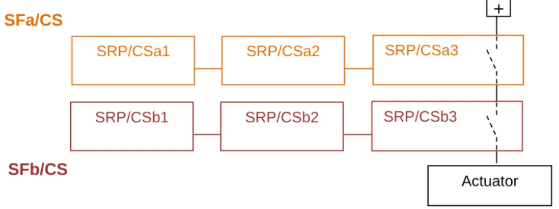
In practice, one or more parts of each safety or "standard" function will transmit stop orders from one or more safety functions to the actuator. An example is given in Figure 8.
In this example, the order to stop issued by safety function SFa passes through SRP/CSb3, which is an integral part of SFb/CS, before reaching the actuator. SRP/CSb3 does not play a functional role in safety function SFa. Questions:
- Could safety function SFa be affected by failure of SRP/CSb3? - If so, what effect would that have on the PL achieved by SFa/CS?
To answer these questions, the types of failure SRP/CSb3 may be subject to must be analysed to determine how these failures might affect the behaviour of safety function SFa.
Study of two sample set-ups:
1st case - SRP/CSb3 has potential-free contact outputs
In this case, failure of SRP/CSb3 has no effect on the behaviour of SFa/CS which remains fully operational.
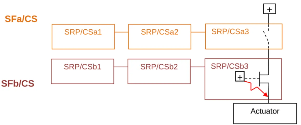
The PL for SFa will be estimated taking only SRP/CSa1, SRP/CSa2 and SRP/CSa3 into account. 2nd case - SRP/CSb3 has electronic outputs
Figure 9 represents a case where potential-free contact outputs are used for function SFa and electronic outputs are used for SFb. Output for SFb (SRP/CSb3) is thought to have failed by reinjecting enough energy (represented by a red line) to supply the actuator.
Figure 8: The signal from SFa/CS to the actuator passes through SRP/CSb3, which is an element of SFb/CS
SFb/CS
SRP/CSa1 SRP/CSa2 SRP/CSa3
Actuator
+
SRP/CSb1 SRP/CSb2 SRP/CSb3
This failure is potentially dangerous to function SFb, since due to its failed output it can no longer order the actuator to stop. This failure is also potentially dangerous for function SFa. Opening the output contacts for this function no longer has any effect, and the actuator does not receive an order to stop. The PL for SFa should therefore be calculated taking SRP/CSa1, SRP/CSa2, SRP/CSa3 and SRP/CSb3 into account.
Conclusions
When physical elements (elements of another safety function or another standard function) are inserted between a SF/CS and the actuator it controls (e.g. Figure 8), the influence of failure of these elements on the SF/CS in question must be analysed.
When failure of these elements has no effect on the SF/CS considered (e.g. potential-free contacts), they need not be taken into account when calculating the PL.
When failure of these elements affects the function of the SF/CS, it may be necessary to revise the design of the function(s) and/or to modify their placement in terms of the interconnections. If these elements are maintained, they must be taken into account when determining the PL of the SF/CS considered.
Warning: If failure of an element performing a "standard" function can affect a SF/CS, it should not be inserted between the SF/CS and its actuator.
8
Notes on the use of SISTEMA software
SISTEMA software assists designers in applying standard EN ISO 13849-1 by taking them through the different design phases recommended by the standard, and by calculating the necessary data without requiring external recourse to the mathematical formulae.
It offers the possibility of using reliability databases for components supplied by some manufacturers.
However, it does not explicitly deal with the steps to be implemented to take systematic failures into account. Thus, the designer must treat them separately by applying Annex G of the standard.
SISTEMA is not a substitute for extensive knowledge of the standard, since the design choices remain the prerogative of the designer. For example, it would be impossible to choose between a safety category and a designated architecture if the different characteristics were not known.
In addition, SISTEMA does not deal with the software elements of safety-related control systems.
Use of this software requires a learning period, since the terminology used is slightly different from that used in EN ISO 13849-1 (e.g. SRP/CS are called SB (for Subsystems) and the notion of elements (as a "sub unit" of a block), which does not appear explicitly in the standard, is introduced). Nevertheless, the breakdown into different elements suggested is very close to that of standard EN 62061.
Figure 9: Example of failure of an electronic output
SFa/CS
SFb/CS
SRP/CSa1 SRP/CSa2 SRP/CSa3
Actuator
+
SRP/CSb1 SRP/CSb2 SRP/CSb3
Use of SISTEMA requires the same preparation as when the design is performed without using it, for example, the designer must:
- specify the safety function (SF),
- specify the SRP/CS (SB), the components (BL and/or EL), - reflect on and choose the planned designated architecture,
- determine the reliability data for the components (B10d, MTTFd) or choose to exclude failures -
note that SISTEMA allows access to some libraries of "manufacturer's characteristics" or the default values for the standard,
- specify the measures against CCF - SISTEMA lists the steps from Annex F of the standard and offers a choice from among them or adoption of other measures,
- analyse potential failures to determine which parts should be considered, - specify the diagnostic functions.
Finally, with or without SISTEMA, the control schemes for the functional and diagnostic parts must be designed adhering strictly to the specifications established and the design choices made.
SISTEMA software facilitates repeated design and makes it possible to generate a final report. Like all software tools, SISTEMA provides traceability which makes it possible to treat projects as they evolve. It is therefore a useful tool provided it is used by personnel who are familiar with the standard, in complement to the standard, as a support and guide for the application of its recommendations.
Note: For the example SF/CS design dealt with in this document, the PL calculated by SISTEMA was the same as that obtained using the simplified method described in the standard.
Annex
1:
Tables of minimal recommendations to achieve a given PL
Minimal recommendations to achieve an "a" PL - Based on Table 7 and using the simplified procedure
Authorised categories Cat B § 6.2.3 Cat 2 § 6.2.5 Respects another category
Respects the requirements of Cat B
MTTFd for each functional channel § 4.5.2 3 years ≤ MTTFd ≤ 100 years (i.e., MTTFd ≥ "Low") 3 years ≤ MTTFd ≤ 100 years (i.e., MTTFd ≥ "Low") Minimum DCavg § 4.5.3 and Annex E DCavg ≥ 0 (DCavg ≥ "Null") DCavg ≥ 60%
(i.e., DCavg ≥ "Low")
CCF
Annex F
N.A. Score ≥ 65
Specificities Components appropriate for
the function
- Well-tried components and safety principles (§ 6.2.4)
- MTTFd,TE to be considered(§ 4.5.4)
check of Functions -
periodicity
N.A. Start of machine,
and periodically (automatic or manual),
and demand rate ≤ 1/100 test rate
check of Functions -
reaction
N.A. If fault detected:
Put in a safe state (stopped) or warn of the danger
Designated architecture
Systematic faults Annex G Annex G
In the following tables, all citations (table, §, annexe)
refer to standard EN ISO 13849-1
Minimal recommendations to achieve a "b" PL - Based on Table 7 and using the simplified procedure
Authorised categories Cat B § 6.2.3 Cat 2 § 6.2.5 Cat 2 § 6.2.5 Cat 3 § 6.2.6 Respects another categoryRespects the requirements of Cat B
Respects the requirements of Cat B
Respects the requirements of Cat B MTTFd for each functional channel § 4.5.2 10 years ≤ MTTFd ≤ 100 years (i.e., MTTFd ≥ "Medium") 10 years ≤ MTTFd ≤ 100 years (i.e., MTTFd ≥ "Medium") 3 years ≤ MTTFd ≤ 100 years (i.e., MTTFd ≥ "Low") 3 years ≤ MTTFd ≤ 100 years (i.e., MTTFd ≥ "Low") Minimum DCavg § 4.5.3 and Annex E DCavg ≥ 0 (DCavg ≥ "Null") DCavg≥ 60% (i.e., DCavg ≥ "Low")
DCavg≥ 90% (i.e., DCavg ≥ "Medium")
DCavg≥ 60% (i.e., DCavg ≥ "Low")
CCF
Annex F
N.A. Score ≥ 65 Score ≥ 65 Score ≥ 65
Specificities Components appropriate for
the function
- Well-tried components and safety principles (§ 6.2.4)
- MTTFd,TE to be considered
(§ 4.5.4)
- Well-tried components and safety principles (§ 6.2.4)
- MTTFd,TE to be considered
(§ 4.5.4)
- Well-tried component and safety principles (§ 6.2.4) - Single fault = safe state
check of Functions -
periodicity
N.A. Start of machine,
and periodically (automatic or manual),
and demand rate ≤ 1/100 test rate
Start of machine,
and periodically (automatic or manual),
and demand rate ≤ 1/100 test rate
If possible, at or before next solicitation
check of Functions -
reaction
N.A. If fault detected:
Put in a safe state (stopped) or warn of the danger
If fault detected:
Put in a safe state (stopped) or warn of the danger
If fault detected:
Put in a safe state (stopped)
Designated architecture
Minimal recommendations to achieve a "c" PL - Based on Table 7 and using the simplified procedure
Authorised categories Cat 1 § 6.2.4 Cat 2 § 6.2.5 Cat 2 § 6.2.5 Cat 3 § 6.2.6 Cat 3 § 6.2.6 Respects another categoryRespects the requirements of
Cat B
Respects the requirements of Cat B
Respects the requirements of Cat B
Respects the requirements of Cat B
Respects the requirements of Cat B MTTFd for each functional channel § 4.5.2 30 years ≤ MTTFd ≤ 100 years (i.e., MTTFd = "High") 30 years ≤ MTTFd ≤ 100 years (i.e., MTTFd = "High") 10 years ≤ MTTFd ≤ 100 years (i.e., MTTFd ≥ "Medium") 10 years ≤ MTTFd ≤ 100 years (i.e., MTTFd ≥ "Medium") 3 years ≤ MTTFd ≤ 100 years (i.e., MTTFd ≥ "Low") Minimum DCavg § 4.5.3 and Annex E DCavg ≥ 0 (DCavg ≥ "Null") DCavg≥ 60% (i.e., DCavg ≥ "Low")
DCavg≥ 90% (i.e., DCavg ≥ "Medium")
DCavg≥ 60% (i.e., DCavg ≥ "Low")
DCavg≥ 90% (i.e., DCavg ≥ "Medium")
CCF
Annex F
N.A. Score ≥ 65 Score ≥ 65 Score ≥ 65 Score ≥ 65
Specificities Well-tried component and
safety principles
- Well-tried components and safety principles (§ 6.2.4)
- MTTFd,TE to be considered (§
4.5.4)
- Well-tried components and safety principles (§ 6.2.4)
- MTTFd,TE to be considered (§
4.5.4)
- Well-tried component and safety principles (§ 6.2.4) - Single fault = safe state
- Well-tried component and safety principles (§ 6.2.4) - Single fault = safe state
check of Functions -
periodicity
N.A. Start of machine,
and periodically (automatic or manual),
and demand rate ≤ 1/100 test rate
Start of machine,
and periodically (automatic or manual),
and demand rate ≤ 1/100 test rate
If possible, at or before next solicitation
If possible, at or before next solicitation
check of Functions -
reaction
N.A. If fault detected:
Put in a safe state (stopped) or warn of the danger
If fault detected:
Put in a safe state (stopped) or warn of the danger
If fault detected:
Put in a safe state (stopped)
If fault detected:
Put in a safe state (stopped)
Designated architecture
Minimal recommendations to achieve a "d" PL - Based on Table 7 and using the simplified procedure
Authorised categories Cat 2 § 6.2.5 Cat 3 § 6.2.6 Cat 3 § 6.2.6 Respects another categoryRespects the requirements of Cat B
Respects the requirements of Cat B
Respects the requirements of Cat B MTTFd for each functional channel § 4.5.2 30 years ≤ MTTFd ≤ 100 years (i.e., MTTFd = "High") 30 years ≤ MTTFd ≤ 100 years (i.e., MTTFd = "High") 10 years ≤ MTTFd ≤ 100 years (i.e., MTTFd ≥ "Medium") Minimum DCavg § 4.5.3 and Annex E DCavg≥ 90% (i.e., DCavg ≥ "Medium")
DCavg≥ 60% (i.e., DCavg ≥ "Low")
DCavg≥ 90% (i.e., DCavg ≥ "Medium")
CCF
Annex F
Score ≥ 65 Score ≥ 65 Score ≥ 65
Specificities - Well-tried components and
safety principles (§ 6.2.4)
- MTTFd,TE to be considered (§
4.5.4)
- Well-tried component and safety principles (§ 6.2.4) - Single fault = safe state
- Well-tried component and safety principles (§ 6.2.4) - Single fault = safe state
check of Functions -
periodicity
Start of machine,
and periodically (automatic or manual),
and demand rate ≤ 1/100 test rate
If possible, at or before next solicitation
If possible, at or before next solicitation
check of Functions -
reaction
If fault detected:
Put in a safe state (stopped) or warn of the danger
If fault detected:
Put in a safe state (stopped)
If fault detected:
Put in a safe state (stopped)
Designated architecture
Minimal recommendations to achieve an "e" PL - Based on Table 7 and using the simplified procedure
Authorised categories Cat 4 § 6.2.7 Respects another categoryRespects the requirements of Cat B MTTFd for each functional channel § 4.5.2 30 years ≤ MTTFd ≤ 100 years (i.e., MTTFd = "High") Minimum DCavg § 4.5.3 and Annex E DCavg≥ 99% (i.e., DCavg = "High")
CCF
Annex F
Annex F (CCF ≥ 65)
Specificities - Well-tried component and
safety principles (§ 6.2.4) - Single fault = safe state
check of Functions -
periodicity
at or before next solicitation
check of Functions -
reaction
Fault detected:
Put in a safe state (stopped)
Designated architecture
Example of design of a SF/CS of PL
r
"d" - Category 3
This example illustrates the design of a SF/CS composed of three SRP/CS, of which one has a known PL (central branch in Graph 1: General design process for a SF/CS conforming to a required PL)
All the design phases have been addressed and are recalled, highlighting the details. Comments deemed necessary to integrate the principles recommended by the standard and based on the graphs, tables and recommendations described in the previous part of this document are included.
The two SRP/CS of unknown PL were developed by applying paragraph 6 of this document. To facilitate comparisons with Graph 2: Details of the design of an SRP/CS to achieve a required PL , extracts of the graph are given at each design step.
The iterations necessary to treat the example are not listed in this document, which presents only the final version of the design phases.
A1. Presentation of the function
This SF/CS will ensure a safety function on a machine including a mobile working element. The rotational movement of this working element is controlled by a hydraulic motor. The risk is linked to the rotational movement (clockwise and anti-clockwise) of the tool. We chose to implement a movable guard to prevent acces to the mobile working element.
The safety function consists in stopping the rotational movement when the movable guard is open. In this example, details are not given on how the required performance level (PLr) was determined (see Annex A in the standard). The initial hypotheses are: PLr "d" and use of category "3" architecture
A safety logic unit is chosen to ensure the logic part of the safety function.
To simplify the examples, the system activating the interlocking device for the movable guard and the hydraulic motor are not considered.
EVD Mhyd Hydraulic Supply Filtration Pressure regulation Figure 10: Basic hydraulic design
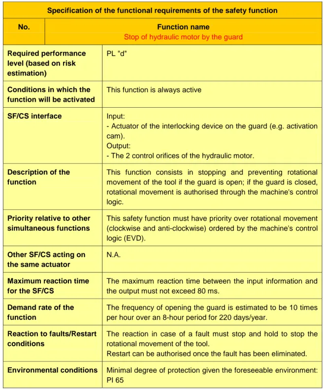
A2. Specifying the safety function
Specification of the functional requirements of the safety function
No. Function name
Stop of hydraulic motor by the guard Required performance
level (based on risk estimation)
PL "d"
Conditions in which the function will be activated
This function is always active
SF/CS interface Input:
- Actuator of the interlocking device on the guard (e.g. activation cam).
Output:
- The 2 control orifices of the hydraulic motor. Description of the
function
This function consists in stopping and preventing rotational movement of the tool if the guard is open; if the guard is closed, rotational movement is authorised through the machine's control logic.
Priority relative to other simultaneous functions
This safety function must have priority over rotational movement (clockwise and anti-clockwise) ordered by the machine's control logic (EVD).
Other SF/CS acting on the same actuator
N.A.
Maximum reaction time for the SF/CS
The maximum reaction time between the input information and the output must not exceed 80 ms.
Demand rate of the function
The frequency of opening the guard is estimated to be 10 times per hour over an 8-hour period for 220 days/year.
Reaction to faults/Restart conditions
The reaction in case of a fault must stop and hold to stop the rotational movement of the tool.
Restart can be authorised once the fault has been eliminated. Environmental conditions Minimal degree of protection given the foreseeable environment:
PI 65
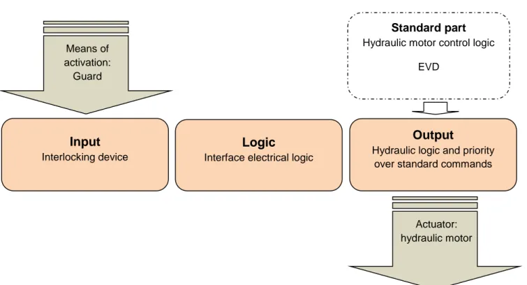
A3. Basic logical structure
Based on the specification of the functional requirements for the function "Stop of hydraulic motor by the guard" (Table 2), the designer develops a logical structure (presented in Figure 11), based on his/her experience in designing similar machines and knowledge of components commonly used in this field. This task can be performed without pre-selecting the material to be used, but often the designer's experience gives them an idea of the type of material he/she expects to use. For example, in the case of this stop function, it is common to use at least one commercially available safety logic unit to facilitate the design and implementation phase.
For this function, the designer plans:
- An "input" part which will be composed of a interlocking device made up of position switch(es). - A "logic" part, which will be composed of a "safety logic unit ". This type of component will make it
possible to create the interface between the input interlocking device and the hydraulic output part. As there are a wide range of safety logic units available on the market, it is often advantageous to choose this option to avoid the need to develop an SRP/CS. This type of component will facilitate the designer's task when developing diagnostics and/or when redundancies.
- An "output" part, which must use hydraulics so as to interface with the hydraulic motor, will be composed of electrically-controlled hydraulic valve(s) so as to be compatible with the control logic of the machine. This part will be used to ensure that the SF/CS has priority over the standard control logic of the motor including EVD.
By physically inserting this part between the standard part and the hydraulic motor, it is certain that the SF/CS will always perform its function, whatever the orders emitted by, or the failures of, the standard part (EVD).
Figure 11: Basic logical structure for the SC/FS
Input
Interlocking device
Logic
Interface electrical logic
Output
Hydraulic logic and priority over standard commands
Standard part
Hydraulic motor control logicEVD Means of activation: Guard Actuator: hydraulic motor
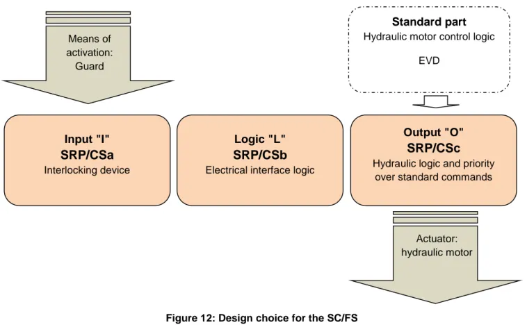
A4. Definition of the necessary SRP/CS to create the SF/CS "Stop of hydraulic motor
by the guard"
Given the logical structure planned for the SF/CS in § A3, the designer applies the central branch of Graph 1: General design process for a SF/CS conforming to a required PL, which consists in creating the SF/CS by associating a logical part of known PL - here a commercially available safety logic unit for the "logic" part - with parts of his/her own design for the input and output. The designer will thus plan to work on the basis of an SRP/CS for each entity in the basic logical structure of the SF/CS.
The design choice for this SF/CS is represented in Figure 12
Note: As the SF/CS includes 3 SRP/CS, each SRP/CS must achieve a PL greater than or equal to the PLd required for the SF/CS (see Warning 2).
Figure 12: Design choice for the SC/FS
Input "I"
SRP/CSa
Interlocking deviceLogic "L"
SRP/CSb
Electrical interface logicOutput "O"
SRP/CSc
Hydraulic logic and priorityover standard commands
Standard part
Hydraulic motor control logicEVD Means of activation: Guard Actuator: hydraulic motor
A5. Designing the SRP/CS
A5.1 Design of SRP/CSaSRP/CSa must be designed to a PL of at least "d" respecting the corresponding criteria, summarised in Table 1 (extract of Annex 1 of this document). The designer chooses to start the process by selecting a category 3 architecture.
Extract of Graph 2: Details of the design of an SRP/CS to achieve a required PL
The specifications of the SRP/CSa are deduced from those of the SF/CS (Table 2).
Specification of the Input SRP/CS Name: SRP/CSa Activation conditions Always active
Interface Input:
- Actuator of the interlocking device on the guard (e.g. activation cam).
Output:
- 2 electrical signals, each representing the state of the guard - closed or not closed - transmitted to the terminals of the interlocking device.
Means of interconnection (iab)
Between SPR/CSa and SPR/CSb: electrical cables exposed to the environmental constraints outside the electrical cabinet. Description As category 3 is targeted, this SRP/CS is designed in two
channels. Each channel generates a logical state "0" as output when the guard is not closed, and a logical state "1" when the guard is closed.
Priorities N.A.
Maximum reaction time The sum of the times for the SPR/CS must not exceed the maximum reaction time specified for the SF/CS (80 ms).
Demand rate The frequency of opening the guard is estimated to be 10 times per hour over an 8-hour period for 220 days/year.
Environmental conditions Minimal degree of protection PI 65 Table 4: Specification of SRP/CSa
The architecture selected as the basis for the design is that shown in Figure 11 of the standard (see Extract 3)
S1
S2
Implementation of the selected architecture.Each individual block ensures the entire function for each of the channels described in the specification for SRP/CSa. There is therefore no need to re-specify each block individually, the elements from the specification of SRP/CSa can be copied.
Choice of material for block diagram 1 The following choice is made (see Figure 14):
Electromechanical position roller switch "S1" with 1 "O"-type contact with direct opening action (in conformity with EN60947-5-1).
Switch will be triggered in the positive mode and installed in line with the manufacturer's recommendations.
For the selected component, the response time is null.
Choice of material for block diagram 2 The following choice is made (see Figure 15):
Electromechanical position roller switch "S2" with 1 "F"-type contact. Switch will be installed in line with the manufacturer's recommendations. For the selected component, the response time is null.
Extract from Graph 2: Details of the design of an SRP/CS to achieve a required PL
Extract from Graph 2: Details of the design of an SRP/CS to achieve a required PL
Figure 14: Switch S1 (shown in the closed guard configuration)
Figure 13: Breakdown of SRP/CSa with block diagrams
Channel 1
Channel 2
Diagram block 1
"Input"
Diagram block 2
"Input"
Diagnostic of
failures by crossed
monitoring
Figure 15: Switch S2 (shown in the closed guard configuration)
Design of the functional channel according to the category 3 designated architecture selected for the SRP/CS
Channels 1 and 2 are composed of "S1" and "S2", respectively. Systematic failures (see Annex A of this document)
Measures against CCF and scoring (see Table 5)
Table 5:Scoring of the measures against CCF for SRP/CSa No
.
Scoring of measures against CCF (Annex F – Informative - of the standard) 1 Separation/Segregation
Physical separation between signal paths – Score achieved 15
Separation by use of a different cable for each position switch x 2 Diversity
Different design/technology or physical principles are used – Score achieved 20
Different activation principle for the switches x
3 Design/application/experience
3.1 Protection against over-voltage, over-pressure, over-current, etc. – Score achieved 15
Input fault taken into account by the safety logic unit x
3.2 Components used are well-tried – Score not achieved 0
No well-tried components are used N
Extract from Graph 2: Details of the design of an SRP/CS to achieve a required PL
Extract from Graph 2: Details of the design of an SRP/CS to achieve a required PL
4 Assessment / analysis
Are the results of a failure mode and effect analysis taken into account against common-cause-failures in design – Score achieved
5
For the switches: common mechanical cause inexistent (principles of activation different due to inverted cam) - separate components
x 5 Competence/training
Score achieved 5
6 Environmental
6.1 Prevention of contamination and electromagnetic compatibility (EMC) against CCF in accordance with appropriate standards– Score achieved
25
Electromechanical parts not subject to EMC x
6.2 Other influences – Score achieved 10
Environmental requirements taken into account when selecting the switches (vibrations, humidity, temperature, shock) depending on the application constraints
x
Total score
95
The total score is ≥ 65: The implemented measures meet the requirements
Analysis of failure modes for each channel and their consequencesExtract from Graph 2: Details of the design of an SRP/CS to achieve a required PL
Component Type of fault retained Consequence Conclusion on the resultant potential danger (for the SRP/CS)
dangerous movement: D non-dangerous movement: ND Switch S1 Welding of type "O" contact Contact does not
open D
Breaking of type "O" contact Contact open ND Activation system blocked
"activated"
Contact open
ND Activation system blocked
"de-activated" or broken
Contact does not
open D
Switch S2 Welding of type "F" contact Contact does not
open D
Breaking of type "F" contact Contact open ND Activation system blocked
"activated"
Contact does not
open D
Activation system blocked "de-activated" or broken
Contact open
ND Table 6: Analysis of failure modes for components of SRP/CSa