Apparent Coexistence of multiple regimes of self-excited
vibrations in deep drilling systems
Alexandre Depouhon
1, and Emmanuel Detournay
21 e-Xstream Engineering, Luxembourg
2 University of Minnesota, USA & CSIRO Petroleum, Australia
February 19, 2009
1 Introduction
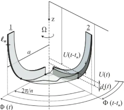
The issue of stick-slip oscillations in the rotary drilling systems used to drill deep boreholes for hydrocarbon exploration and production has been explored by Richard et al. [1]. Their analysis
Figure 1: Discrete model. of the dynamics of the drill bit is based on a discrete model of
the drillstring (Fig. 1), and rate-independent bit-rock interaction laws. The latter accounting for the regenerative cutting effect tak-ing place at the bit level ( Fig. 2) the equations of motion yield a system of discontinuous state-dependent delayed differential equa-tions. Numerical simulations with this model produce self-excited stick-slip oscillations and show the existence of an anti-resonance drilling regime, during which large amplitude axial vibrations of the bit stabilize its angular motion. Further work carried out by Germay et al. [2] has formalized the model using the concept of Filippov differential inclusion and brought to light the existence of quasi-periodic solutions for particular parametric configurations of the model. Here, we investigate the slow dynamical behavior that is inherent to particular parametric configurations of this model, and provide, using linear stability analysis, an explanation to the quasi-periodic solutions observed in numerical simulations [1, 2].
2 Governing equations
Using the time scale t∗=!I/C and the length scale L∗= 2C/εa2, with ε being the intrinsic specific energy of the rock, a the bit radius, C and I the torsional stiffness and polar mass moment of inertia of the drillstring, Richard et al. [1] derived the dimensionless equations of motion for an idealized bit, consisting of n identical radial blades regularly spaced by 2π/n radians, drilling a homogeneous rock
u""= ψ(W0− W(t0u,t0ϕ)), ϕ""+ ϕ = T0− T (t0u,t0ϕ),
where u and ϕ are the bit axial displacement and angular position perturbations to the steady-state solution, the prime denotes differentiation with respect to the dimensionless time ¯t= t/t∗,
W and T are the dimensionless weight- and torque-on-bit, ψ is the system number and the
subscript0 refers to a steady-state quantity. Both W and T are functions of the history of u and ϕ, denoted byt
0uandt0ϕ, respectively.
In drilling conditions, the scaled efforts W and T are given by the bit-rock interaction laws and have experimentally been shown to depend on two distinct processes, respectively, a cutting
Figure 2: Regenerative cutting.
and a frictional contact ones, i.e. W = Wc+ Wf and T = Tc+ Tf. While the cutting forces are proportional to the bit penetration per revolution, δ, the contact forces are characterized by a threshold following a transition that is function of both δ and the direction of the relative velocity of the cutters with respect to the rock [3]
W = n"δn+ Wnf # , T = n"δn+ βWnf # , Wf n = λn 1 sat 0 $ α + Θ+ α∗ 2α∗ % 1 sat 0 $ nδn δ∗ % ,
where δn(t0u,t0ϕ)is the dimensionless depth of cut per blade, which introduces a delay in the equations of motion as the height of rock ahead of a blade depends on the motion history of the bit, see Figure 2. Also, β is the bit geometry number, λnreflects the wear state of the bit, and
αand Θ characterize the direction of the relative velocity of the bit with respect to the rock and
the inclination of the blade wear flat. As α changes along the radius of the bit, the above law is strictly valid for core barrels only. The sat function denotes the saturation operator, while the parameters α∗ and δ∗ are rock-dependent parameters that delimit the upper saturation level of the contact force. Whenever the bit sticks and stands still, i.e., u"+ v
0 = ϕ"+ ω0 = 0, v0
and ω0 being the stationary axial and angular velocities of the bit, the boundary condition is given by the equilibrium of the bit, until the torque built up by twisting of the drillstring is large enough to overcome the resistant torque and trigger motion. By further developing the equations, the model reads,
u"" = nψ&−[u − ˜u + v0(¯tn− ¯tn,0)] + Wn,0f − Wnf
'
,
ϕ""+ ϕ = n&−[u − ˜u + v0(¯tn− ¯tn,0)] + β(Wn,0f − Wnf)
'
,
where ˜u = u(¯t − ¯tn) is the delayed axial perturbation and ¯tn is the state-dependent delay, defined by the threshold condition
( ¯t ¯ t−¯tn (ϕ"(s) + ω 0)ds = 2π n.
3 Slow dynamics
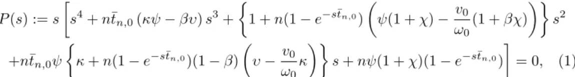
Previous works [1, 2] have shown that for the stick-slip or anti-resonance regimes to occur, the steady-state motion of the bit should be unstable. To assess the local stability of the stationary solution of the model, the poles of the linearized system around that solution are to be located in the complex plane. If any of them has a strictly positive real part, the steady-state is unstable. In case all the poles are located in the left half of the complex plane, the trivial solution is
stable. The poles are the roots of the characteristic equation, computed from the linearized system, P (s) := s ) s4+ n¯tn,0(κψ − βυ) s3+ * 1 + n(1 − e−s¯tn,0) $ ψ(1 + χ)−v0 ω0 (1 + βχ)%+s2 +n¯tn,0ψ * κ + n(1− e−s¯tn,0)(1 − β) $ υ−ωv0 0 κ %+ s + nψ(1 + χ)(1− e−s¯tn,0) , = 0, (1) with the parameters κ, υ and χ depending on the steady-state drilling conditions and the bluntness of the bit.
Numerical investigations of the solutions of (1) have shown that for particular parametric configurations, the linearized system has two unstable poles close to ±i, the poles of the torsional pendulum. Although they have a positive real part and thus the stationary solution is unstable, the divergence of the system following any perturbation is very slow due to the smallness of their real part. Accordingly, depending on the external perturbations the system is subject to, the response of the system appears to converge to different periodic solutions and there is apparent coexistence of drilling regimes. Figure 3 exemplifies this feature. The unperturbed system stays at the stationary solution while a small perturbation generates a slow transient regime of quasi-periodic oscillations that will eventually converge to the attractive stick-slip limit cycle. However, this limit cycle is immediately reached after a large perturbation.
0 20 40 0 0.5 1 1.5 2 2.5 3 3.5 1960 1980 2000 Time response V elocities Time Pert. 3 Pert. 2 Pert. 1 -2 -1.5 -1 -0.5 0 0.5 1 1.5 2 0 0.5 1 1.5 2 2.5 3
3.5 Angular phase plane
Pert. 3
Pert. 2 Pert. 1
Figure 3: Response of the system to an angular perturbation.
4 Conclusion
A physically consistent model, that recovers stick-slip oscillations of deep drilling systems and captures the coexistence of multiple drilling regimes observed in the fields and in lab experi-ments, has been developed. By performing a linear stability analysis of the delayed differential model, we provide a justification to the coexistence of drilling regimes as we brought to light the slow dynamical nature of such self-excited vibrations.
References
[1] Richard T., Germay C. and Detournay E.: A simplified model to explore the root cause of stick-slip vibrations in drilling systems with drag bits. Journal of Sound and Vibration 307:432–456, 2007. [2] Germay C., van de Wouw N., Nijmeijer H. and Sepulchre R.: Nonlinear drillstring dynamics
anal-ysis. SIAM Journal on Applied Dynamical System. In press. 2009.
[3] Besselink B.: Analysis and validation of self-excited drill string oscillations. MSc Thesis, Technical University Eindhoven. 2008.