an author's
https://oatao.univ-toulouse.fr/21831
https://doi.org/10.1016/j.compstruct.2018.08.045
Dubary, Nicolas and Bouvet, Christophe and Rivallant, Samuel and Ratsifandrihana, Léon Damage tolerance of an
impacted composite laminate. (2018) Composite Structures, 206. 261-271. ISSN 0263-8223
Damage tolerance of an impacted composite laminate
N. Dubary
a,b, C. Bouvet
a,⁎, S. Rivallant
a, L. Ratsifandrihana
baInstitut Clément Ader, CNRS UMR 5312, Université de Toulouse, ISAE-SUPAERO– 10 av. E. Belin, 31055 Toulouse Cedex 4, France bSegula Aerospace & Defence, Segula Technologies– Immeuble EQUINOX – bat. 1, 24 Boulevard Déodat de Séverac, 31770 Colomiers, France
Keywords: Low-velocity impact Damage tolerance
Compression After Impact (CAI) Numerical modelling
A B S T R A C T
Composites are known to be vulnerable to out-of-plane loading such as impact. Investigating the residual properties of the laminate as a function of damage detection is the main purpose of impact damage tolerance design in aeronautics. As a good alternative to experimental campaigns, numerical approaches would lead to saving of time. The model developed in Institut Clément Ader over the last years enables representation of
behavior of composite laminates subjected to low velocity/low energy impact– including permanent indentation
– and Compression After Impact. Damage such as permanent indentation, fiber failures, matrix cracks and de-lamination are taken into consideration at each step thanks to a discrete ply modelling. The work presented here deals with the use of this model to make a composite laminate design optimization according to impact damage tolerance design. A method to improve optimization by reducing computation time is also proposed, based on a “best candidates” selection.
1. Introduction
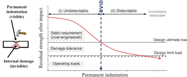
Because of their high strength-to-weight ratio along with the will of using lighter structures, composites attract an increasing interest in manyfields. However, their vulnerability to out-of-plane loading such as impacts leads to an over-dimensioning. Low velocity impacts can occur during manufacturing or operation on composite structures and can result in a significant reduction of the residual properties without visibly marking the surface. This external damage corresponding to the dent left by the impact event is called permanent indentation (PI). In aeronautics, requirements and design are based on the visibility of the damage (Fig. 1): under a certain level of detectability the structure should withstand ultimate loads; beyond this level the impacted structure should withstand limit loads without sudden failure until the detection of the damage during inspection. This level of detection is called“Barely Visible Impact Damage”, or BVID[1–3], and is linked to the geometry, to the properties of the structure and to the impact en-ergy. So even damaged and without detectability, the design should ensure that the structure bears in-service loads: this is the principle of damage tolerance. As a matter of fact, impact damage tolerance design of composite relies on two important parameters: residual strength and detectability of the impact given by the permanent indentation.
1.1. About modelling composites
From understanding to predictive work, many studies have been run on damage induced by Low-Velocity Impact (LVI) since 90’s [2–9]. Analytical, semi-analytical models and formulations are thefirst ap-proaches for predicting induced damage during quasi-static response or LVI and for characterizing residual properties of the structure
[2–4,10–13]. For instance, critical load could be analytically de-termined to predict delamination growth[10]. Even if these approaches are quite efficient in certain domains, the complexity of the phenomena implies that numerical methodologies have to be developed. The FE method is a relevant approach to characterize the behavior of compo-site structures and to provide information on the impact damage phe-nomena. Reliable impact and Compression After Impact (CAI) simula-tions would be a valuable tool to replace tests and take place in the test pyramid[14,15]: this is the aim of virtual testing. The complexity of composites is that damage depend on the design of the laminate in terms of stacking sequence, ply thickness, nature offibers, kind of re-inforcement… driving to a different repartition of stress in the laminate and so to a reduction or an increase in stress location.
In order to have a faithful and reliable behavior of the laminate during simulation, it is necessary to sufficiently represent the events occurring during loading and damage development. These damage could be classified into two parts: intralaminar damage developed in-side the ply (matrix cracking,fiber breakage or fiber/matrix debonding)
⁎Corresponding author.
E-mail address:[email protected](C. Bouvet).
https://doi.org/10.1016/j.compstruct.2018.08.045
and interlaminar damage developed at the interface between two plies, namely delamination. To have a good accuracy, the main damage captured by a numerical low velocity impact simulation are matrix cracking, fiber breakage and delamination [16 18]driving to a“re levant physics of the impact process” from under BVID to perforation range of impact[18].
Important research has been done on understanding, capturing and modelling delamination with good results [19 27], on the effect of
delamination on the residual strength[28,29]showing a reduction of the residual strength in presence of delamination. Since the introduc tion of the cohesive zone model (CZM) in the 60’s[30 32], delamina tion in composites is nowadays commonly simulated using cohesive elements and interface elements. For instance, interface elements are integrated in the model[16,33,34], and used with contact algorithms and friction between delaminated plies. Turon et al.[35]and Harper et al.[36]studied influence of cohesive zone interface strength para meters on mixed mode behavior. For instance, Harper et al. conclude that one should pay attention to the length of the cohesive zone on what depends the accuracy of the interfacial stresses. Relatively short length of the cohesive zone enables better results. Other approaches exist with Li et al.[23]who use fracture mechanics to simulate the delamination growth based on VCCT to evaluate the energy release rates. Or Menna et al.[17]who choose a modelling of the bond between plies through distributed spring connections, each ply being modelled by three di mensional eight nodefinite elements. Delamination is modelled by the use of a surface to surface tiebreak contact algorithm based on the knowledge of interlaminar properties (normal and shear strengths).
Concerning intraply damage modelling,fiber breakage and matrix cracking can be approached by continuum damage mechanics model ling with three dimensional solid elements including internal damage variables and a degradation of material properties following the di rection as in[16,18,37]. All of these approaches are meso scale simu lation strategies.
Faggiani and Falzon[33]propose a continuum damage mechanics approach for fiber breakage and matrix failure, each in tensile and compressive failure mode, using continuum shell elements. Modelling of matrix cracking using extendedfinite element method is also con ducted by Iarve et al. [34]. This enables independence of the mesh orientation. Lopes et al. [18]also use cohesive elements in the ply between three dimensional elements in the material direction to cap ture matrix cracking. Likewise, de Moura and Gonçalves [25]place interface elements inside layers where matrix cracking is experimen tally observed, implying the need of a previous study.
The importance of coupling between interlaminar and intralaminar damage is also admitted in literature[18,22 27,29,34,38]. The use of cohesive elements inside the ply in the material direction to capture
matrix cracking and get a good coupling with the delamination is an other point to obtain accurate damage predictions. It is admitted that matrix cracking has a precursory role on delamination.
Then to estimate the residual strength and evaluate the damage tolerance of the laminate, interest is focused on modelling Compression After Impact with, for instance, some quite accurate models developed by Gonzalez et al.[39], Dang and Hallett[29], Tan et al.[40]or re cently published by Panettieri et al.[41].
Gonzalez et al.[39]agree that the predictions deteriorate with an increasing number of layers. Their predictions are close to the experi mental values, with a maximum relative error of 20% for the strength obtained during CAI.
Dang and Hallett[29]use a model that do not take into account fiber failure (impact are carried out at very low energy, and fiber fail ures do not occur or can be negligible in this case). During CAI, they link the compressive strength to the occurrence of significant delami nation events.
Tan et al.[40] manage to capture both the qualitative and the quantitative aspects of intralaminar and interlaminar damage during impact and CAI. However they have little trouble to capture the good direction of delamination propagation, while having a good re presentation of the extended area.
Panettieri et al. [41]show the importance of the parameters of cohesive elements on the CAI result and on the computational cost. They point out that a compromise has to be made. They also admit than a reliable numerical approach could“not only lower the cost associated with the test but also enhance the design of composite structures”.
Finally, related to the impact damage tolerance designing philo sophy, attention is given to permanent indentation as a predictive mark to evaluate the residual capabilities of the structure [42]. This phe nomenon is not well controlled yet, because it depends on several parameters: plate geometry, material, stacking sequence, impact energy or impactor shape, etc… and its origin is complex: local fiber failure
[43], debris accumulation, local plasticity, etc.
Some formulations exist to integrate dent during impact test simu lations:“plastic like” model included in the matrix behavior to take into account matrix cracking, plasticity and blocking debris [44], using anisotropic elasto plasticity theory [45], non linear shear of the in tralaminar damage model [20,40] with combination of continuum theories of plasticity and continuum damage mechanics[37].
1.2. Objectives of this study
The Discrete Ply Model (DPM) developed at the Institut Clément Ader by Bouvet et al. makes possible to capture damage such as per manent indentation, delamination,fiber breakage and matrix cracks for
are also set up. According to the ASTM D7137/D7137M standards[50], they consist of two longitudinal stabilizing knives spaced 90 mm and two clamping blocks at the lower and upper sides of the plate spaced 130 mm (Fig. 3b).
2.4. Experimental validation
A previous validation of DPM capability to represent both impact and CAI has been done and presented in[46]. Validation was based on experimental/numerical comparisons of delamination (C scan), impact force/displacement curves and CAI strengths from various laminates with 0.5 mm thickness plies (0.5 mm plies in the numerical simulation, two 0.25 mm combined plies in the experiments).
During this study, new tests were done to validate the model with 0.25 mm thickness plies, in order to be able to simulate more realistic laminates. They consist in 25 J impact and CAI tests on 4 × 100 × 150 mm3 laminates made of T700/M21 UD tapes. ASTM
D7137/D7137M standards were used, and 6 specimens tested: 3 dif ferent stacking sequences, tested twice for repeatability.
A: [45/−45/90/0/90/0/45/−45]S
K: [45/−45/0/45/−45/0/902]S
O: [45/−45/45/−45/90/0/90/0]S
Fig. 4presents impact force/displacement curves for the three A, K and O specimens: two experimental curves for each specimen, and the associated simulation. A very good agreement was found for all three cases, both during loading and unloading phases.
To have more comparison data, C scan were also performed for one of each specimen type. The obtained delamination maps are also pre sented onFig. 4, beside delamination coming from the numerical si mulation. Specimen A and K present good correlations, with very good numerical estimations of the delaminated interfaces, shapes and areas. Finally, permanent indentations (Fig. 5a) were also measured 48 h after the end of impact tests, using digital image correlation. They are in accordance even if the numerical results are overestimated. One can explain this difference with the relaxation phenomena causing too high numerical permanent indentation value. Moreover, the evolutions of permanent indentation from one specimen to another are the same in experiments and simulations. At this level of modelling, it can be as sumed that the result is good.
Importance isfinally given to the residual strength got during CAI on the three stacking sequences A, K and O.Fig. 5b shows that, even if, like for permanent indentation, the results are slightly overestimated (10 15%), the ranking in terms of performance is well represented. This means that the simulation is also able to give a hierarchy in terms of layups strength capacity, which is the most important in design when searching for the best laminate.
3. Numerical approach: Laminate design optimization with impact damage tolerance
3.1. Classical approach
Previous work and results presentedfirst in this article show that the DPM model is advanced enough to propose an impact damage tolerance design approach. A classical numerical design approach would be to cover the laminate design space by changing stacking se quences, materials, number of plies, and calculate residual stress at BVID. As the concept of damage tolerance in composite is based on the visibility of the damage (residual strength is calculated at BVID), the optimization loop is based on an inner loop to determine the impact energy level to obtain a permanent indentation (PI) equal to BVID (Fig. 6). This inner loop does not necessitate the full impact and CAI calculation as the permanent indentation is calculated at the end of the impact energy and the CAI calculation is run only for the BVID energy
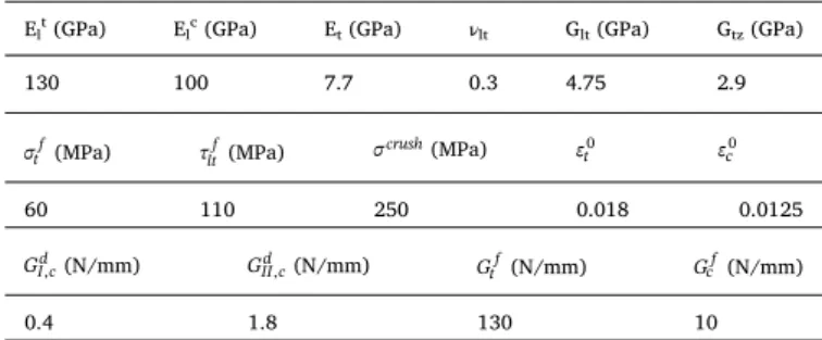
Elt(GPa) Elc(GPa) Et(GPa) νlt Glt(GPa) Gtz(GPa)
130 100 7.7 0.3 4.75 2.9
σtf(MPa) τltf(MPa) σcrush(MPa) εt0 εc0 60 110 250 0.018 0.0125
GI cd, (N/mm) GII cd, (N/mm) Gtf(N/mm) Gcf(N/mm)
0.4 1.8 130 10
Menna et al. talk about the mesh dependency of the result: “the composite material failure behavior is influenced by the element size affecting the absorbed energy which varies with the element length and converges for small element dimensions” [17]. They use elements of
approximatively 0.657 mm size. In our case, to obtain a good propa gation of the last interface delamination (at the non impacted face), the mesh is reduced to 0.833 mm size elements. It also has to be noticed that the thickness of elements is smaller than during previous validation of the model (0.25 mm against 0.5 mm) [46], and the number of in
terfaces is increased causing a more complex model. It was observed that the result is more reliable when the element length is smaller. To avoid excessive time calculation, this size of 0.833 mm is the limit of the model to get a good delamination: beyond this size the propagation at the last interface does not occur.
2.2. Permanent indentation modelling
As previously seen, the permanent indentation is the mark left onto the surface after an impact event. It is defined as the difference in a direction normal to the face of the specimen between the lowest point in the dent and the surface that is undisturbed by the dent [49]. Its
origin is not well controlled yet, but previous studies show that it is mainly linked to fiber breakage, matrix plasticity, or blocking debris
[41]. In the model, it is represented thanks to a pseudo plastic non
return law in intra ply interface elements.
The capability of DPM to represent permanent indentation is vali dated by the curves return during impact unload (in impact force dis placement curves). It is to be noticed that this model does not take into account the natural relaxation of the plate after impact: the permanent indentation value reduces during a couple of days following an impact event by elasticity behavior. For this reason, all measures of experi mental permanent indentation value are carried out at least 48 h after impact tests and could be smaller than the numerical ones measured at the end of impact simulation.
2.3. Material and boundary conditions
The model is so used to simulate experimental impact and CAI tests on 4 × 100 × 150 mm3 rectangular laminate plates of T700/M21 UD
carbon/epoxy composite. Properties used in the model are presented in
Table 1. The number of plies is fixed at 16 plies of 0.25 mm thickness. Orientations in the stacking sequence are limited to 0°, ± 45° and 90° with the same fiber percentage for each direction. Considering sym metrical reasons, only a half plate is meshed. The boundary conditions are given by the contact between the plate and a fixed rigid body, re presenting experimental condition tests presented hereafter (Fig. 3).
For the impact test, the plate is supported by a 75 × 125 mm2
window and is impacted at its center by a 2 kg hemispherical impactor of 16 mm diameter, numerically assumed non deformable (Fig. 3a). Following the impact, a relaxation step is simulated. This step put the plate in quasi static state by eliminating major vibrations and waves induced by the impact event. During this step CAI boundary conditions
Table 1
important to put into perspectives the results of the optimization done with the DPM model. To the author’s knowledge, the DPM is one of the most efficient models that can represent impact, impact induced da-mage (including PI), and CAI within the same model, with such a result quality: representativeness of mechanisms and values of impact force evolution, PI, CAI, etc. However, due to the great complexity of the phenomenon and of the model, one must not expect DPM model to give a veryfine accuracy in the current state of virtual tools development. The model makes possible the ranking of laminates' residual strength (with a quite satisfactory accuracy). This is the most important point in the case of design optimization, to find the best structure. However, there is also a significant dispersion in experimental results that makes unnecessary the search for an extreme precision in the estimation of BVID energy level.
Anyway, nowadays, an experimental validation of the optimized laminate obtained by numerical design is still necessary.
5. Conclusion
Using the Discrete Ply Model, a numerical impact damage tolerance sizing is proposed. This work is possible thanks to the ability of the DPM in capturing main damage as fibre failure, matrix cracking and dela-mination from impact to CAI event. In thefirst part of the study, an experimental/numerical comparisons campaign was performed, showing quite accurate results in dent depth and residual strength prediction, two key parameters in this approach.
After this validation, the model was used to make a laminate design optimization with damage tolerance. In afirst part, a reduced design space made of 19 laminates was proposed and full impact and CAI calculations were done at different impact energy level around the
energy necessary to obtain a visible damage equal to BVID. Simple interpolations were then done to determine the best laminates in terms of damage tolerance strength, showing the ability of DPM to make a composite design optimization with damage tolerance. However, within the 19 samples studied, no clear rule or trend emerges to justify the impact damage tolerance of a given stacking sequence. This result again underlines the importance of numerical simulations development for composite damage prediction, as no practical rules can be estab-lished for an industrial use.
The principle of a classical optimization loop, more time-efficient, was also presented, but not applied here, the objective of the study being to study the evolution of CAI residual stress versus permanent indentation curves in order to propose an improved approach.
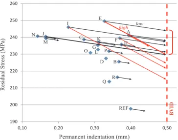
This approach is based on the knowledge of an approximate linear decrease of CAI stress when permanent indentation increases. It en-ables, from a single full impact and CAI calculation for all studied la-minate, a rough estimation of the CAI strength. Thus, it is possible to define a reduced set of “best candidates” to perform a finer optimiza-tion. This enables reduction of computation time, which is a critical point in composite numerical simulations.
However, even with this reduction of the global number of simu-lations to perform during design optimization, the 36 h duration (on 20 CPUs) for a single impact and CAI simulation is still too high to be applied to more industrial design spaces made of hundreds or thousands laminates. An effort to drastically reduce models calculation time has to be done.
Acknowledgments
Authors would like to gratefully acknowledge CALMIP (CALcul en Midi-Pyrénées) for access to the HPC resources under the allocation p1026.
References
[1] Tropis A, Thomas M, Bounie JL, Lafon P. Certification of the composite outer wing of the ATR72. J Aerosp Eng 1994;209:327–39.
[2] Huang KY, De Boer A, Akkerman R. Analytical modeling of impact resistance and damage tolerance of laminated composite plates. AIAA J 2008;46(11):2760–72. [3] Combes RC. Design for damage tolerance. J Aircraft 1970;7(1):18–20. [4] Abrate S. Impact on Composites Structures. Cambridge University Press; 1998. [5] Eve O. Etude du comportement des structures composites endommagées par impact
basse vitesse PhD Thesis France: University of Metz; 1999
[6] Richardson MOW, Wisheart MJ. Review of low-velocity impact properties of com-posite materials. Compos A 1996;27(12):1123–31.
[7] Cantwell WJ, Morton J. The impact resistance of composite materials– a review. Composites 1991;22(5):347–62.
[8] Feraboli P, Kedward KT. Enhanced evaluation of the low-velocity impact response of composite plates. AIAA J 2004;42(10):2143–52.
[9] Pilchak AL, Uchiyama T, Liu D. Low velocity impact response of small-angle la-minated composites. AIAA J 2006;44(12):3080–7.
[10] Olsson R. Analytical prediction of large mass impact damage in composite lami-nates. Compos A 2001;32:1207–15.
[11] Zhou G. The use of experimentally-determined impact force as damage measure in impact damage resistance and tolerance of composite structures. Compos Struct 1998;42:375–82.
[12] Suemasu H, Kumagai T, Gozu K. Compressive behavior of multiply delaminated composite laminates part 1: experiment and analytical development. AIAA J 1998;36(7):1279–85.
[13] Suemasu H, Kumagai T. Compressive behavior of multiply delaminated composite laminates part 2:finite element analysis. AIAA J 1998;36(7):1286–90.
[14] Rouchon J. Certification of Large Aircraft Composite Structures, Recent Progress and New Trends in Compliance Philosophy, 17th ICAS, Stockholm, Sweden, 1990. [15] Acar E, Haftka RT, Kim NH. Effects of structural tests on aircraft safety. AIAA J
2010;48(10):2235–48.
[16] Lopes CS, Camanho PP, Gurdal Z, Maimi P, Gonzalez EV. Low-Velocity impact damage on dispersed stacking sequence laminates. Part II: numerical simulations. Compos Sci Technol 2009;69(7–8):937–47.
[17] Menna C, Asprone D, Caprino G, Lopresto V, Prota A. Numerical simulation of impact tests on GFRP composite laminates. Int J Impact Eng 2011;38:677–85. [18] Lopes CS, Sadaba S, Gonzalez C, Lorca JL, Camanho PP. Physically-sound
simula-tion of low-velocity impact onfiber reinforced laminates. Int J Impact Eng 2015;92:3–17.
[19] Schoeppner GA, Abrate S. Delamination threshold loads for low velocity impact on composite laminate. Compos A 2000;31:903–15.
Fig. 13.“Best candidates” method: principle of CAI estimation at BVID.
Fig. 14.“Best candidates” method applied to the 19 laminates, from 25 J
[20] Shi Y, Swait T, Soutis C. Modelling damage evolution in composite laminate sub-jected to low velocity impact. Compos Struct 2012;94(9):2902–13.
[21] Elder DJ, Thomson RS, Nguyen MQ, Scott ML. Review of delamination predictive methods for low speed impact of composite laminates. Compos Struct
2004;66(1–4):677–83.
[22] Lammerant L, Verpoest I. Modelling of the interaction between matrix cracks and delaminations during impact of composite plates. Compos Sci Technol 1996;56(10):1171–8.
[23] Li S, Reid SR, Zou Z. Modelling damage of multiple delaminations and transverse matrix cracking in laminated composites due to low velocity lateral impact. Compos Sci Technol 2006;66:827–36.
[24] Razi H, Kobayashi AS. Delamination in cross-ply laminated composite subjected to low-velocity impact. AIAA J 1993;31(8):1498–502.
[25] de Moura MFSF, Gonçalves JPM. Modelling the interaction between matrix cracking and delamination in carbon–epoxy laminates under low velocity impact. Compos Sci Technol 2004;64:1021–7.
[26] Bachrach WE, Hansen RS. Mixedfinite-element method for composite cylinder subjected to impact. AIAA J 1989;27(5):632–8.
[27] Hallett SR, Jiang WG, Khan B, Wisnom MR. Modelling the interaction between matrix cracks and delamination damage in scaled quasi-isotropic specimens. Compos Sci Technol 2008;68(1):80–9.
[28] Aslan Z, Sahin M. Buckling behaviour and compressive failure of composite lami-nates containing multiple large delaminations. Compos Struct 2009;89:382–90. [29] Dang TD, Hallett SR. A numerical study on impact and compression after impact
behavior of variable angle tow laminates. Compos Struct 2013;96:194–206. [30] Dugdale DS. Yielding of steel sheets containing slits. J Mech Phys Solids
1960;8:100–8.
[31] Makhecha DP, Kapania RK, Johnson ER, Dillard DA. Dynamic fracture analysis of adhesively bonded joints using explicit methods. AIAA J 2007;45(11):2778–84. [32] Barenblatt GI. The mathematical theory of equilibrium of cracks in brittle fracture.
Adv Appl Mech 1962;7:55–129.
[33] Faggiani A, Falzon BG. Predicting low-velocity impact damage on a stiffened composite panel. Compos A 2010;41(6):737–49.
[34] Iarve EV, Gurvich MR, Mollenhauer DH, Rose CA, Davila CG. Mesh-independent matrix cracking and delamination modeling in laminated composites. Int J Numer Methods Eng 2011;88:749–73.
[35] Turon A, Camanho PP, Costa J, Renart J. Accurate simulation of delamination growth under mixed-mode loading using cohesive elements: Definition of inter-laminar strengths and elastic stiffness. Compos Struct 2010;92:1857–64. [36] Harper PW, Sun L, Hallett SR. A study on the influence of cohesive zone interface
element strength parameters on mixed mode behavior. Compos A 2012;43:722–34. [37] Donadon MV, Iannucci L, Falzon BG, Hodgkinson JM, de Almeida SFM. A
pro-gressive failure Model for composite laminates subjected to low velocity impact damage. Comput Struct 2008;86:1232–52.
[38] Bouvet C, Castanié B, Bizeul M, Barrau JJ. Low velocity impact modelling in la-minate composite panels with discrete interface elements. Int J Solids Struct 2009;46(14–15):2809–21.
[39] Gonzalez EV, Maimi P, Camanho PP, Turon A, Mayug JA. Simulation of drop-weight impact and compression after impact tests on composite laminates. Compos Struct 2012;91(11):3364–78.
[40] Tan W, Falzon BG, Chiu LNS, Price M. Predicting low velocity impact damage and Compression-After-Impact (CAI) behavior of composite laminates. Compos A 2015;71:212–26.
[41] Panettieri E, Fanteria D, Danzi F. Delamination growth in compression after impact test simulations: Influence of cohesive elements parameters on numerical results. Compos Struct 2016;137:140–7.
[42] Wardle BL, Lagace PA. On the use of dent depth as an impact damage metric for thin composite structures. J Reinf Plast Compos 1997;16(12):1093–110.
[43] Chen P, Shen Z, Xiong J. Failure mechanisms of laminated composites subjected to static indentation. Compos Struct 2006;75(1–4):489–95.
[44] Bouvet C, Rivallant S, Barrau JJ. Low velocity impact modeling in composite la-minates capturing permanent indentation. Compos Sci Technol
2012;72(16):1977–88.
[45] He W, Guan Z, Li X, Liu D. Prediction of permanent indentation due to impact on laminated composites based on an elasto-plastic model incorporatingfiber failure. Compos Struct 2013;96:232–42.
[46] Hongkarnjanakul N, Bouvet C, Rivallant S. Validation of low velocity impact modeling on different stacking sequences of CFRP laminates and influence of fibre failure. Compos Struct 2013;106:549–59.
[47] Rivallant S, Bouvet C, Hongkarnjanakul N. Failure analysis of CFRP laminates subjected to Compression After Impact : FE simulation using discrete interface elements. Compos A 2013;55:83–93.
[48] Israr HA, Rivallant S, Barrau JJ. Experimental investigation on mean crushing stress characterization of carbon-epoxy plies under compressive crushing mode. Compos Struct 2013;96:357–64.
[49] ASTM /D7136M,“Standard Test Method for Measuring the Damage Resistance of a fiber-reinforced polymer matrix composit to a drop-weight impact event,” ASTM editor, 2015.
[50] ASTM D7137/D7137M,“Standard Test Method for Compressive Residual Strength Properties of Damaged Polymer Matrix Composite Plates,” ASTM editor, 2012.