HAL Id: hal-01858266
https://hal-mines-paristech.archives-ouvertes.fr/hal-01858266
Submitted on 28 Aug 2018
HAL is a multi-disciplinary open access
archive for the deposit and dissemination of
sci-entific research documents, whether they are
pub-lished or not. The documents may come from
teaching and research institutions in France or
abroad, or from public or private research centers.
L’archive ouverte pluridisciplinaire HAL, est
destinée au dépôt et à la diffusion de documents
scientifiques de niveau recherche, publiés ou non,
émanant des établissements d’enseignement et de
recherche français ou étrangers, des laboratoires
publics ou privés.
Recent advances in the finite element modelling of
ductile fracture at mesoscale
Pierre-Olivier Bouchard, Victor-Manuel Trejo-Navas, Modesar Shakoor, Thilo
Morgeneyer, Ante Buljac, Lukas Helfen, François Hild, Marc Bernacki
To cite this version:
Pierre-Olivier Bouchard, Victor-Manuel Trejo-Navas, Modesar Shakoor, Thilo Morgeneyer, Ante
Bul-jac, et al.. Recent advances in the finite element modelling of ductile fracture at mesoscale. Procedia
Manufacturing, Elsevier, 2018, 15, pp.39-45. �10.1016/j.promfg.2018.07.167�. �hal-01858266�
ScienceDirect
Available online at Available online at www.sciencedirect.comwww.sciencedirect.com
ScienceDirect
Procedia Manufacturing 00 (2017) 000–000
www.elsevier.com/locate/procedia
* Paulo Afonso. Tel.: +351 253 510 761; fax: +351 253 604 741
E-mail address: psafonso@dps.uminho.pt
2351-9789 © 2017 The Authors. Published by Elsevier B.V.
Peer-review under responsibility of the scientific committee of the Manufacturing Engineering Society International Conference 2017.
Manufacturing Engineering Society International Conference 2017, MESIC 2017, 28-30 June
2017, Vigo (Pontevedra), Spain
Costing models for capacity optimization in Industry 4.0: Trade-off
between used capacity and operational efficiency
A. Santana
a, P. Afonso
a,*, A. Zanin
b, R. Wernke
b a University of Minho, 4800-058 Guimarães, PortugalbUnochapecó, 89809-000 Chapecó, SC, Brazil
Abstract
Under the concept of "Industry 4.0", production processes will be pushed to be increasingly interconnected, information based on a real time basis and, necessarily, much more efficient. In this context, capacity optimization goes beyond the traditional aim of capacity maximization, contributing also for organization’s profitability and value. Indeed, lean management and continuous improvement approaches suggest capacity optimization instead of maximization. The study of capacity optimization and costing models is an important research topic that deserves contributions from both the practical and theoretical perspectives. This paper presents and discusses a mathematical model for capacity management based on different costing models (ABC and TDABC). A generic model has been developed and it was used to analyze idle capacity and to design strategies towards the maximization of organization’s value. The trade-off capacity maximization vs operational efficiency is highlighted and it is shown that capacity optimization might hide operational inefficiency.
© 2017 The Authors. Published by Elsevier B.V.
Peer-review under responsibility of the scientific committee of the Manufacturing Engineering Society International Conference 2017.
Keywords: Cost Models; ABC; TDABC; Capacity Management; Idle Capacity; Operational Efficiency 1. Introduction
The cost of idle capacity is a fundamental information for companies and their management of extreme importance in modern production systems. In general, it is defined as unused capacity or production potential and can be measured in several ways: tons of production, available hours of manufacturing, etc. The management of the idle capacity
Procedia Manufacturing 15 (2018) 39–45
2351-9789 © 2018 The Authors. Published by Elsevier B.V.
Peer-review under responsibility of the scientific committee of the 17th International Conference on Metal Forming. 10.1016/j.promfg.2018.07.167
10.1016/j.promfg.2018.07.167 2351-9789
© 2018 The Authors. Published by Elsevier B.V.
Peer-review under responsibility of the scientific committee of the 17th International Conference on Metal Forming. Available online at www.sciencedirect.com
Sci enceDi r ect
Procedia Manufacturing 00 (2018) 000–000www.elsevier.com/locate/procedia
2351-9789 © 2018 The Authors. Published by Elsevier B.V.
Peer-review under responsibility of the scientific committee of the 17th International Conference on Metal Forming.
17th International Conference on Metal Forming, Metal Forming 2018, 16-19 September 2018,
Toyohashi, Japan
Recent advances in finite element modelling of ductile fracture at
mesoscale
P.-O. Bouchard
a,*, Victor Trejo Navas
a, Modesar Shakoor
a,f, Thilo Morgeneyer
b,
Ante Buljac
b, c, Lukas Helfen
d,e, François Hild
c, Marc Bernacki
aa Mines ParisTech, PSL - Research University, CEMEF - Centre de mise en forme des matériaux, CNRS UMR 7635, CS10207 rue Claude
Daunesse 06904 Sophia Antipolis Cedex, France.
b Mines ParisTech, PSL - Research University, Centre des matériaux, CNRS UMR 7633, BP 87 91003 Evry, France c LMT, ENS Paris-Saclay, CNRS, Université Paris-Saclay, 61 avenue du Président Wilson, 94235 Cachan Cedex, France d ANKA/Institute for Photon Science and Synchrotron Radiation, Karlsruhe Institute of Technology (KIT), 76131 Karlsruhe, Germany
e European Synchrotron Radiation Facility (ESRF), 38043 Grenoble, France f Department of Mechanical Engineering, Northwestern University, Evanston, IL 60208, USA
Abstract
This work addresses ductile fracture at the meso-scale by accounting for the influence of particles on nucleation, growth and coalescence mechanisms for complex loading paths. A finite element approach was developed to model and study 3D heterogeneous microstructures with interfaces defined by level-set functions and the use of a body fitted mesh adaption technique. Specific developments were also carried out in order to model failure mechanisms occurring both during the nucleation and the coalescence stages. Initial 3D microstructures of nodular graphite cast iron are obtained from X-ray laminography pictures. In-situ tensile tests with varying stress states are carried out and nucleation, growth and coalescence mechanisms are observed. Digital volume correlation is used to access to 3D displacement (and strain) field in the bulk. These data are also used to prescribe exact boundary conditions on the faces of the finite element domain. The finite element approach therefore enables to study strain and stress states in critical areas and aims at improving the understanding of coalescence mechanisms (internal necking of the intervoid ligament or void-sheet mechanism) by comparing finite element simulations with experimental observations and digital volume correlation results. This finite element approach is used to conduct a parametric study on the relative position of three voids on void growth and coalescence modes. It is shown that 2D views of coalescence mechanisms may sometimes be misleading.
© 2018 The Authors. Published by Elsevier B.V.
* Corresponding author. Tel.: +33-4-93-67-89-21, Fax: +33-4-92-38-97-52
E-mail address: pierre-olivier.bouchard@mines-paristech.fr
Available online at www.sciencedirect.com
Sci enceDi r ect
Procedia Manufacturing 00 (2018) 000–000www.elsevier.com/locate/procedia
2351-9789 © 2018 The Authors. Published by Elsevier B.V.
Peer-review under responsibility of the scientific committee of the 17th International Conference on Metal Forming.
17th International Conference on Metal Forming, Metal Forming 2018, 16-19 September 2018,
Toyohashi, Japan
Recent advances in finite element modelling of ductile fracture at
mesoscale
P.-O. Bouchard
a,*, Victor Trejo Navas
a, Modesar Shakoor
a,f, Thilo Morgeneyer
b,
Ante Buljac
b, c, Lukas Helfen
d,e, François Hild
c, Marc Bernacki
aa Mines ParisTech, PSL - Research University, CEMEF - Centre de mise en forme des matériaux, CNRS UMR 7635, CS10207 rue Claude
Daunesse 06904 Sophia Antipolis Cedex, France.
b Mines ParisTech, PSL - Research University, Centre des matériaux, CNRS UMR 7633, BP 87 91003 Evry, France c LMT, ENS Paris-Saclay, CNRS, Université Paris-Saclay, 61 avenue du Président Wilson, 94235 Cachan Cedex, France d ANKA/Institute for Photon Science and Synchrotron Radiation, Karlsruhe Institute of Technology (KIT), 76131 Karlsruhe, Germany
e European Synchrotron Radiation Facility (ESRF), 38043 Grenoble, France f Department of Mechanical Engineering, Northwestern University, Evanston, IL 60208, USA
Abstract
This work addresses ductile fracture at the meso-scale by accounting for the influence of particles on nucleation, growth and coalescence mechanisms for complex loading paths. A finite element approach was developed to model and study 3D heterogeneous microstructures with interfaces defined by level-set functions and the use of a body fitted mesh adaption technique. Specific developments were also carried out in order to model failure mechanisms occurring both during the nucleation and the coalescence stages. Initial 3D microstructures of nodular graphite cast iron are obtained from X-ray laminography pictures. In-situ tensile tests with varying stress states are carried out and nucleation, growth and coalescence mechanisms are observed. Digital volume correlation is used to access to 3D displacement (and strain) field in the bulk. These data are also used to prescribe exact boundary conditions on the faces of the finite element domain. The finite element approach therefore enables to study strain and stress states in critical areas and aims at improving the understanding of coalescence mechanisms (internal necking of the intervoid ligament or void-sheet mechanism) by comparing finite element simulations with experimental observations and digital volume correlation results. This finite element approach is used to conduct a parametric study on the relative position of three voids on void growth and coalescence modes. It is shown that 2D views of coalescence mechanisms may sometimes be misleading.
© 2018 The Authors. Published by Elsevier B.V.
* Corresponding author. Tel.: +33-4-93-67-89-21, Fax: +33-4-92-38-97-52
40 P.-O. Bouchard et al. / Procedia Manufacturing 15 (2018) 39–45
2 Author name / Procedia Manufacturing 00 (2018) 000–000
Peer-review under responsibility of the scientific committee of the 17th International Conference on Metal Forming.
Keywords: Ductile fracture; Micro-scale; Finite element; Level-set function; Mesh adaption
1. Introduction
Predicting and avoiding ductile fracture during metal forming processes is still a very hot and open scientific topic despite the tremendous efforts of the metal forming community. This is due to the complexity of the thermomechanical and metallurgical mechanisms occurring during forming processes (large plastic strains under multiaxial and non-proportional loading conditions). At the macroscopic scale, the prediction of ductile fracture is usually addressed using uncoupled failure criteria, coupled continuum damage mechanics approaches or damage models based on porous-plasticity theory (see Ref. [1] for a comparison of such approaches for cold metal forming applications). These approaches do not explicitly account for the material microstructure and phenomena such as the influence of particles (nature, shape, orientation and distribution) on damage anisotropy or nucleation/coalescence mechanisms cannot be properly addressed. However, it has been shown that such a microstructure can have a direct impact on damage mechanisms [2].
This work studies ductile damage issues at mesoscale, where particles and voids are considered and meshed in 2D and 3D volumes. In order to understand the underlying physical mechanisms for complex loading paths, three modern techniques are seamlessly coupled: (i) X-ray laminography to image in situ tested large flat samples made of ductile materials [3], (ii) digital volume correlation to measure 3D displacement (and strain) fields in the bulk [4], and (iii) 2D/3D finite element simulations using the experimental information on multiple length-scales [5-7]. First, the finite element methodology developed to model void nucleation, growth and coalescence mechanisms is described. The overall strategy is then presented through applications on nodular graphite cast iron. Finally a numerical sensitivity analysis is conducted to study the influence of the position of three voids on coalescence mechanisms.
2. Finite element methodology
The studied domains are 2D or 3D Representative Volume Elements generally composed of a matrix, particles, and voids. A specific body-fitted mesh adaption technique was developed in [5] so as to preserve the geometric properties of level-set functions as well as the volume and morphology of each component of the microstructure, even at large plastic strains. A particularity of the present framework is that voids are also meshed, meaning that there are mesh elements inside cracks. These elements are only used for remeshing purposes, and measurement of void volume fraction, but have no stiffness or constitutive behavior. Their effect is hence no different than actual voids (that would not be meshed). The matrix is defined by an elastic-plastic behavior and particles are assumed to be elastic brittle. They are assumed to debond or fail before yielding can occur. Both nucleation mechanisms are based on local stress-based criteria that are described in details in [8]. Fig. 1 shows an example where a microstructure containing several particles is submitted to tension. Void nucleation by debonding (for example top-left corner) and by particles failure (right side) can be observed up to 50% of elongation.
Coalescence is characterized by the initiation of micro-cracks between voids leading to final fracture. From a numerical point of view, such coalescence mechanism can be modelled naturally by internal necking in the intervoid ligament when level-set functions get in contact and merge. If a mechanical criterion (to be defined) is reached in the intervoid ligament, it is also possible to propagate a straight crack from one void to another. Void coalescence will be studied in section 4 and more details can be found in [5, 9].
P.-O. Bouchard et al. / Procedia Manufacturing 15 (2018) 39–45 41
Author name / Procedia Manufacturing 00 (2018) 000–000 3
Fig. 1. Equivalent plastic strain for 3D microstructure under tensile loading with both nucleation mechanisms activated at Representative Volume Elements elongation of (a) 25% and (b) 50% (from [8]).
3. Application to nodular cast iron
The studied material is a commercial nodular graphite cast iron (specimens supplied by M. Kuna, L. Zybell and M. Horn from TU Bergakademie Freiberg). At the microscale, this material exhibits a ferritic steel matrix and graphite nodules. Under tensile loading, ductile fracture is mainly driven by a very early debonding of the nodules from the matrix, and coalescence of the subsequent nucleated voids [10]. Due to their very low load carrying capacity under tensile loading, it is suggested [10] to model such nodules as voids. With this simplifying assumption, the material is considered as a two-phase microstructure with an elastic-plastic ferritic matrix and voids.
In order to study the growth and coalescence stage, a specific methodology has been developed. This methodology is based on the following steps:
• Acquisition of the real initial 3D microstructure based on X-Ray laminography [3]. These pictures are taken from a region located at the center of a flat tensile specimen with two holes machined at 45° with respect to the loading direction. These pictures are also recorded at different stages of the tensile test so as to observe coalescence mechanisms.
• Global DVC to measure displacement fields whose kinematic basis is made of the shape functions of 8-noded elements [11]. The digital volume correlation registration technique used to measure 3D displacement fields in the bulk of samples is based on a global approach [12] which consists in minimizing gray level residuals on the whole region of interest and in using kinematic fields based on FE discretizations.
• Meshing of the real initial microstructure (two-phase material) of a domain included in the region of interest and application of boundary conditions coming from the digital volume correlation step.
The whole methodology is presented in detail in [6].
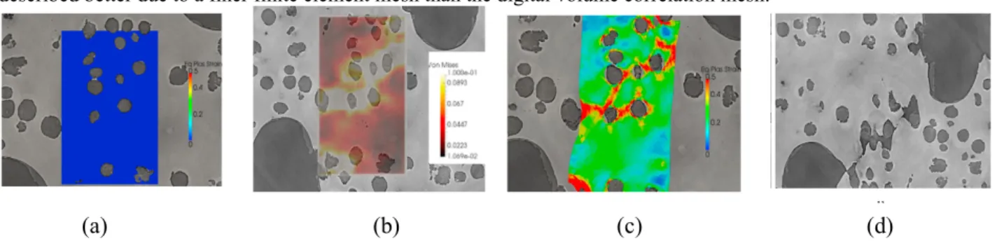
Based on this approach, it is possible to study void growth and strain increase in the ferritic matrix both using digital volume correlation data and finite element simulations. Regarding finite element simulations, note that applying the exact digital volume correlation boundary condition is really important compared to classical finite element multiscale strategies, as explained in [7]. Fig. 2 shows a 2D cut of the region of interest at different stages of the tension test. Fig. 2(a) is a superimposition of the finite element strain field and the microstructure at t0. Fig. 2(b)
and Fig. 2(c) show a superimposition of the von Mises strain field at t1 obtained respectively by digital volume
42 P.-O. Bouchard et al. / Procedia Manufacturing 15 (2018) 39–45
4 Author name / Procedia Manufacturing 00 (2018) 000–000
observed at the last stage before complete fracture illustrated in Fig. 2d (at tf). Note that localization bands are
described better due to a finer finite element mesh than the digital volume correlation mesh.
Fig. 2. Observation of void growth and coalescence on 2D cut of the region of interest at different stages of tension test and superimposition of digital volume correlation and finite element equivalent strain field on microstructure.
The observations from X-Ray laminography enable to exhibit the two main coalescence mechanisms. The most observed coalescence mode is due to internal necking between neighboring voids with plastic localization in the intervoid ligaments. For lower stress triaxiality ratios, a shear driven localization mode, often called void-sheet coalescence, can also be observed. This void-sheet coalescence mode is not yet perfectly understood. In [13], digital volume correlation analyses were conducted in areas corresponding to these two coalescence mechanisms. These analyses showed that the equivalent strain reached at the last stage before failure was approximately the same for the two different coalescence mechanisms. However, it must be noted that void-sheet coalescence is usually observed in 2D micrographs or 2D X-ray tomography pictures without accounting for the influence of other voids possibly located deeper in the material. In order to study the influence of such 3D effect, a numerical parametric study is conducted in the next section.
4. Void coalescence analysis
4.1. Influence of voids position on coalescence
In the following, a 3D cubic domain containing three spherical voids is considered. The size of the domain is large enough to assure negligible interaction with the boundaries. The domain, illustrated in Fig. 3(a), is submitted to tension in the vertical y direction by applying a normal velocity Vy up to a vertical strain Eyy equal to 0.5. Symmetry conditions, indicated by red arrows, are used on three faces of the domain. Finally, on the two remaining faces, velocities are prescribed so as to respect a given stress state (stress triaxiality ratio equals 1 and Lode angle is fixed to 0.34 in the following). The matrix is assumed to be elastic perfectly plastic. Three voids (radius = 50 µm) are located at the center of the domain (See Fig. 3(b)). The two external voids centers are placed at z = 0. They are positioned at 45° with respect to the loading direction. The distance between the center of the domain (noted O) and their closest surface is noted d1. The third void, named internal void, is centered along the x and y axes (y = 0 and x = 0) and its position varies along z. d2 denotes the distance between the center of the domain and its closest surface. For the sake of simplicity, d1 and d2 will be normalized by the voids radius R in the following. The sensitivity analysis is conducted with d1 varying between 1 and 3.25 and d2 varying between 1 and 4. For each configuration, the minimum intervoid distance, normalized void volume and equivalent plastic strain at the center between voids (see Fig. 3(c)) can be plotted.
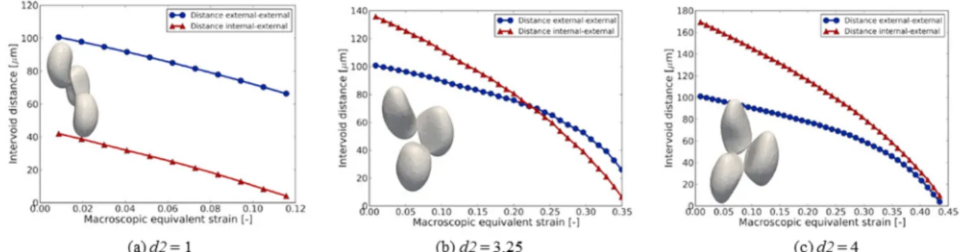
In the following, the results will be shown for d1 = 1 and for d2 varying between 1 and 4. For the complete analysis of the domain space, the reader can refer to [9]. Fig. 4 shows external-external and internal-external distances evolution for three different values of d2.
For d2 = 1 (Fig. 3(a)), the distance between the two external voids is twice the one between external voids and the internal void. The decrease of this distance is similar and coalescence arises when the internal-external voids distance reaches zero for a strain value close to 0.12.
P.-O. Bouchard et al. / Procedia Manufacturing 15 (2018) 39–45 43
Author name / Procedia Manufacturing 00 (2018) 000–000 5 When d2 is increased to 3.25 (Fig. 3(b)), the internal-external distance is higher at the beginning but its decrease is faster than the external-external one. Again, coalescence occurs between external voids and the internal one. It is interesting to notice the acceleration of the decrease at the end just before coalescence occurs.
Finally, when d2 is increased to 4 (Fig. 3(c)), both curves exhibit a fast decrease at the end with coalescence occurring between the two external voids first and almost instantaneously between the internal and the two external voids.
It is also interesting to notice that increasing the d2 distance from 1 to 4 leads to an increase of the equivalent strain at coalescence from 0.12 to 0.43. The complete sensitivity analysis, presented in [9], enables to plot the coalescence strain as a function of d1 and d2.
For each configuration, a view of the 3 voids at the onset of coalescence is shown in Fig. 3. The shape of the elongated voids depends on the initial configuration and the presence of the internal void clearly influences these coalescence mechanisms. In order to investigate further this influence an analysis is conducted with and without the presence of the internal void in the next section.
Fig. 3. (a) 3D domain with prescribed boundary conditions; (b) relative position between two external voids and internal void; (c) localization of sensor for strain analysis.
Fig. 4. Plot of external-external and internal-external distances for d1 = 1 and 3 different values of d2.
Internal void External void External void d1 d2 Internal-external distance External-external distance
(a)
(b)
(c)
44 6 Author name / Procedia Manufacturing 00 (2018) 000–000 P.-O. Bouchard et al. / Procedia Manufacturing 15 (2018) 39–45
4.2. Effect of internal void on void growth and coalescence mechanism
In order to study the influence of an internal void on void growth and coalescence mechanisms, two simulations were conducted. The first simulation accounted for the two external voids only, at a normalized distance d2 = 1. The second simulation was identical, but with the presence of an internal void at a normalized distance d1 = 1.
The analysis showed that the presence of the internal void influences significantly void growth with a faster void volume fraction than in the presence of 2 external voids only. In such a configuration, the use of a Rice & Tracey void growth model would underestimate void growth, as shown in [9].
In addition, it is interesting to observe the coalescence modes obtained for these two configurations. Fig. 5(a) (resp. Fig. 5(b)) shows the voids shape at coalescence for the configuration with two voids (resp. 3 voids). In the configuration with 3 voids it can be noticed that coalescence occurs between the internal and the two external voids simultaneously. Fig. 5(c) shows the equivalent plastic strain field in a 2D view just prior to coalescence for the 3 voids configuration. The strain localization observed here is due to the internal necking occurring between the internal void and the two external voids. For this same 3 voids configuration, Fig. 5(d) shows a 2D view of the void volume fraction just after coalescence occurs. With such a 2D view, one would conclude that coalescence occurs by void-sheeting, whereas the full 3D analysis conducted here demonstrates that this coalescence is due to internal necking between the internal void and the two external voids.
Fig. 5. Voids shape at onset of coalescence for (a) 2 voids and (b) 3 voids. (c) Equivalent plastic strain for 3 voids configuration plotted in 2D view just prior to coalescence and (d) void volume fraction for 3 voids configuration plotted in 2D view just after coalescence occurred.
5. Conclusion
The new FE methodology presented here enables to mesh 3D heterogeneous microstructures and to study voids nucleation, growth and coalescence for large plastic strain. Initial meshes are based on X-Ray laminography pictures for a nodular graphite cast iron. A global digital volume correlation approach was developed to study displacement (and strain) fields in the bulk thanks to the gray level of laminography pictures taken at different stages of tensile tests. These digital volume correlation fields can also be used to prescribe exact boundary conditions for finite element calculations on the real microstructure. Such an approach was conducted for the first time in [6] and the influence of boundary conditions on void growth was studied in [7].
Particular attention was paid here to the coalescence modes observed experimentally for these in-situ tension experiments on nodular cast iron. 2D views usually used to observe such failure mechanisms show both internal necking and void-sheet coalescence modes. However, such a material exhibits a very high density of nodules and, in some cases, what looks like void-sheet coalescence may actually come from the presence of other nodules or voids in the depth. To figure out the influence of such 3D effects, a parametric study was conducted with two external voids in the same plane and with the presence of a third void in the depth. This study showed that, for specific
P.-O. Bouchard et al. / Procedia Manufacturing 15 (2018) 39–45 45
Author name / Procedia Manufacturing 00 (2018) 000–000 7 configurations, 2D views may be misleading since they show void-sheeting coalescence mode (Fig. 5(d)) whereas coalescence is due to the presence of the third void in the depth and to plastic localization and internal necking between this third void and the two first ones (Fig. 5(b)).
However, it must be noted that this sensitivity analysis was conducted here for an elastic-plastic material with no hardening. Hardening would undoubtedly slow down plastic localization. It would therefore be interesting to confirm these results with a matrix exhibiting hardening. The variation of the stress state would also be interesting for further investigations.
Acknowledgements
This work was performed within the COMINSIDE project funded by the French Agence Nationale de la Recherche (ANR-14-CE07-0034-02 grant). We also acknowledge the European Synchrotron Radiation Facility for provision of beamtime at beamline ID15, experiment ME 1366. It is also a pleasure to acknowledge the support of BPI France (DICCIT project), and of the Carnot M.I.N.E.S institute (CORTEX project).
References
[1] T.S. Cao, C. Bobadilla, P. Montmitonnet, P.O. Bouchard, A comparative study of three ductile damage approaches for fracture prediction in cold forming processes, Journal of Material Processing Technology, 216 (2015) 385–404.
[2] P.O. Bouchard, L. Bourgeon, H. Lachapele, E. Maire, C. Verdu, R. Forestier, R.E. Logé, On the influence of particles distribution and reverse loading on damage mechanisms of ductile steel alloys, Materials Science and engineering: A, 496 (2008) 223–233.
[3] T. Morgeneyer, L. Helfen, I. Sinclair, H. Proudhon, F. Xu, T. Baumbach, Ductile crack initiation and propagation assessed via in situ synchrotron radiation computed laminography, Scripta Materialia, 65-11 (2011) 1010–1013.
[4] T.F. Morgeneyer, T.T. Thomas, L. Helfen, T. Baumbach, I. Sinclair, S. Roux, F. Hild, In situ 3D observation of early strain localisation during failure of thin Al alloy (2198) sheet, Acta Materialia, 69 (2014) 78–91.
[5] M. Shakoor, M. Bernacki, P.O. Bouchard, A new body-fitted immersed volume method for the modeling of ductile fracture at the microscale: Analysis of void clusters and stress state effects on coalescence, Engineering Fracture Mechanics, 147 (2015) 398–417.
[6] A. Buljac, M. Shakoor, J. Neggers, M. Bernacki, P.O. Bouchard, L. Helfen, T.F. Morgeneyer, F. Hild, Numerical validation framework for micromechanical simulations based on synchrotron 3D imaging, Computational Mechanics, 59-3 (2017) 419–441.
[7] M. Shakoor, A. Buljac, J. Neggers, F. Hild, T.F. Morgeneyer, L. Helfen, M. Bernacki, P.O. Bouchard, On the choice of boundary conditions for micromechanical simulations based on 3D imaging, International Journal of Solids and Structures, 112 (2017) 83–96.
[8] M. Shakoor, M. Bernacki, P.O. Bouchard, Ductile fracture of a metal matrix composite studied using 3D numerical modeling of void nucleation and coalescence, Engineering Fracture Mechanics, 189 (2018) 110–132.
[9] V.T. Navas, M. Bernacki, P.O. Bouchard, Void growth and coalescence in a three-dimensional non-periodic void cluster, International Journal of Solids and Structures, 139-140 (2018) 65–78.
[10] G. Hütter, L. Zybell, M. Kuna, Micromechanisms of fracture in nodular cast iron: From experimental findings towards modeling strategies– A review, Engineering Fracture Mechanics, 144 (2015) 118–141.
[11] A. Buljac, T.T. Thomas, T.F. Morgeneyer, L. Helfen, S. Roux, F. Hild, Slant strained band development during flat to slant crack transition in AA 2198 T8 sheet: in situ 3D measurements, International Journal of Fracture, 200 (2016) 49–62.
[12] S. Roux, F. Hild, P. Viot, D. Bernard, Three-dimensional image correlation from X-ray computed tomography of solid foam, Composites Part A: Applied Science and Manufacturing, 39 (2008) 1253–1265.
[13] A. Buljac, Understanding, observation and quantification of ductile failure mechanisms via 3D imaging, PhD Université Paris-Saclay, (2017).
![Fig. 1. Equivalent plastic strain for 3D microstructure under tensile loading with both nucleation mechanisms activated at Representative Volume Elements elongation of (a) 25% and (b) 50% (from [8])](https://thumb-eu.123doks.com/thumbv2/123doknet/11570070.297482/4.816.171.653.113.383/equivalent-microstructure-nucleation-mechanisms-activated-representative-elements-elongation.webp)