HAL Id: tel-03003852
https://pastel.archives-ouvertes.fr/tel-03003852
Submitted on 13 Nov 2020HAL is a multi-disciplinary open access
archive for the deposit and dissemination of sci-entific research documents, whether they are pub-lished or not. The documents may come from teaching and research institutions in France or abroad, or from public or private research centers.
L’archive ouverte pluridisciplinaire HAL, est destinée au dépôt et à la diffusion de documents scientifiques de niveau recherche, publiés ou non, émanant des établissements d’enseignement et de recherche français ou étrangers, des laboratoires publics ou privés.
Towards the full field modeling and simulation of
annealing twins using a Finite Element Level Set method
Julien Fausty
To cite this version:
Julien Fausty. Towards the full field modeling and simulation of annealing twins using a Finite Element Level Set method. Mechanics of materials [physics.class-ph]. Université Paris sciences et lettres, 2020. English. �NNT : 2020UPSLM022�. �tel-03003852�
Pr ´epar ´ee `a MINES Paristech
Towards the full field modeling and simulation of annealing
twins using a Finite Element Level Set method.
Soutenue par
Julien Fausty
Le 23 janvier, 2020 ´ Ecole doctorale no364ED SFA
Sp ´ecialit ´eM ´ecanique
num ´erique
et
Mat ´eriaux
Composition du jury :
Julien BRUCHON
Professeur, ´Ecole Nationale Sup ´erieure des Mines de Saint- ´Etienne
Pr ´esident
Carl KRILL
Professeur, Ulm University Rapporteur
Lukasz MADEJ
Professeur, AGH University of Science
and Technology Rapporteur
Daniel PINO MU ˜NOZ
Maˆıtre de Conf ´erence, MINES Paristech Examinateur
Jean-Michel FRANCHET
Chef de Projet, SAFRAN Tech Membre invit ´e
Nathalie BOZZOLO
Professeur, MINES Paristech Directrice de th `ese
Marc BERNACKI
Aknowledgements
I would like to start by thanking all the people I’m likely to forget in the following text. There are many more people to whom I owe my success up until now than I can give credit to in one page. I would also like to thank the group SAFRAN, and more specifi-cally Jean-Michel Franchet and Mika¨el Peillard, for financing this project and giving me the opportunity to complete this thesis. A special thanks also goes to S´elim Kraria, Carole Torrin and the whole IT department of the CEMEF without whom this work would be impossible. Also, special thanks to Marie-Fran¸coise Guenegan for being such an adminis-trative genius.
Next I would like to thank Nathalie Bozzolo, my doctoral co-supervisor, for building this research proposal from scratch and trusting me to complete it. Without her tenacity many of the things I took for granted in this investigation would likely have been much more difficult. Marc Bernacki, my other co-supervisor, is one of the most hard-working, accessible and generous people I know. I would like to thank him, first, for putting up with my stubbornness and, second, for believing that good ideas can come from Phd students. Without his regular check-ups and demands for more precise formulations and more numerous simulations this manuscript would very likely be of much lesser quality.
I would like to thank all the friends I made here in the lab for their support, the laughs, the coffees and the pints. Ludovic Maire introduced me to life at the CEMEF and helped me find my bearings in the beginning. He was always there if I needed him for something inside or outside of the lab. Suzanne Vernier, thank you for being there at the CEMEF and always being the voice of reason and a great friend. I would like to thank Malik Durand, Brayan Murgas, Baptiste Flipon, In`es Sahli, Anthony Seret, Diego Uribe, Juhi Sharma, Jules Baton, Carlos Mensah, Corentin Perderiset, David Ruiz Sarrazola, Vincent Maguin, Ghalia Guiza, Pierrick Rambaud, Romain Fleurisson, Dana¨ı Polychronopoulou and Gerry Agboda for their “water-cooler” discussions and general joviality. A big thanks goes out to my Columbian dynamic duo Sebastian Florez and Karen Alvarado. I probably would have gone crazy if you guys weren’t here to set me back straight. Thanks for the great discussions, your boundless patience and empathy and drive to always do the right thing for your friends and family.
Lulu and Sandro I want to thank for their great hospitality. I don’t know how I would have been able to get my head out of the thesis without the weekends in Toulon. The uno
games, the laughs, the ap´eros and the shared joys have been instrumental in keeping my spirits high. You guys are great and I’m happy I get to keep it going forever.
L´ea and Alexis, I’ll try to find the words to describe how lucky I am to have found you two but I don’t think I’ll succeed. Alexis, I’m so grateful that I got put into you’re office at the get go because I don’t think I could have picked a better person to spend 3 years with. From my perspective our relationship evolved very quickly from colleague towards friend. I can’t say how happy I am to have met someone so thoughtful and who shares the same love of beer as me. L´ea, when I first met you, you were my colleague’s girlfriend. Now, I do believe that I can truly call you friend. Thank you for all the good times we had together smoking cigarettes, eating Indian food and talking metaphysics. You are a beautiful person with so much to offer the world and I know you know it and I think that that’s great. Both of you are friends that I don’t want to lose. My single biggest regret in leaving the CEMEF is not being able to see you two on a daily basis.
I would also like to thank my Mom. Mom, you know I would never have been able to do this without you. I want to thank you for the drive you taught me to have and the creativity you’ve instilled in me all these years. It hasn’t always been easy to be your son, but the things you’ve taught me over the years are largely what got me through this thesis work and I can’t thank you enough. I also want to thank you for you’re unrelenting pride in my work and career path and for caring enough to try to understand what the work is about. You’re an amazing person and I’m very lucky to have you.
Romane, my love. You know that this thesis would never have happened the way it did if it wasn’t for you. Thank you for always being there, always contributing, always taking up my problems as “our” problems and not making any distinctions between your well being and mine. Thank you for sharing your life with me, the laughs and the tears, the joy and the anger, the good and the bad and everything in between. You are really the only one who knew how difficult these three years have been and you are also the one who has always thought about my well being throughout. It’s a good thing you were here to tell me when to stop working and have fun because if not I fear I would have never made it. I’m so grateful to have such a special person in my life and I wouldn’t have it any other way.
Introduction
Since the advent of high performance computing, or HPC for short, our computing ca-pabilities have been growing exponentially over time. The HPC market has followed this trend, going from a 5 billion dollar industry in the year 2000 to a 21 billion dollar market in 2015 [1]. The applications in the R&D space are multifold, going from the most precise simulations of the human brain (Human Brain Project) to the understanding of graphene’s properties and potential (Graphene Flagship). This growth is an indicator not only of the improvements in the technology underlying the computing infrastructure (both hardware and software), but also of the democratization of its use. Computer models have become integral actors in the design, validation and manufacturing of products ranging from au-tomobiles to detergents. The industrial leaders in almost every sector are now using HPC technologies to improve their products as well as their processes.
Perhaps no industry is more in need of advanced computer models than the aerospace sector. Indeed, airplane manufacturers face multi-physics problems that combine elements of fluid-mechanics, thermal efficiency, energy conversion, acoustics, structural mechanics, metallurgy and many more. Engineers are faced with all the constraints that the physical laws impose naturally on flight along with the safety regulations and international norms necessary to set a standard for passenger transport when improving the performance of aircraft. The parameter space to be explored while designing an airplane is also enormous, every piece of the machine encompasses many variables. As such, the number of possible design iterations, which is on par with the number of points in the parameter space, is extensive. Moreover, the strict minimum number of validating tests, of the order of the number of regulatory and physical constraints, that must be run on each design is also substantial. If physical experiments had to be run on each prototype in order to evaluate its relevance, new technologies would be far and few in between and the costs would be monumental. Therefore, models are of immense importance in the design process.
The possibilities afforded to industry, and particularly the aerospace sector, by HPC technologies are the abilities to create more complex models that can be solved in shorter times. Indeed, companies are integrating powerful computer modeling approaches not only into product design, but also into process design. Massive gains in both time and energy can be obtained with an optimized manufacturing process. However, also as a consequence of the growing requirements on optimized components from more complicated design loops,
the requirements on the manufacturing processes are becoming more stringent. As the specifications list for individual pieces of complex machinery become longer, the margin of error in the manufacturing process is becoming thinner.
Typically, the nickel based superalloy disks in aircraft motors are forged components that follow complex processing routes in order to meet both mechanical strength and thermal resistance requirements at the hearts of turbines. The dimensions of the disks must be controlled throughout the process of heating, deforming and cooling the material potentially in multiple combinations of these three steps. However, as the prescriptions on the properties of the disks multiply in order to meet the demands of the next genera-tions of aircraft motors, the parameter space of the forging process has remained largely untouched as being multiple combinations of heat and force. As such, disk manufactur-ers are looking to fine-tune their processes in order to produce components with better properties. However, the link between the processing of a forged metallic component and its final properties is known to be controlled for a large part by its microstructure. This is the general goal of the OPALE industrial chair co-financed by the French National Re-search Agency (ANR) and the SAFRAN group. In order to systematically optimize the manufacturing process of nickel based superalloys numerical methods and experimental studies must work hand in hand. This work is part of the numerical aspect of the OPALE project.
The evolution of a metallic material’s microstructure along its manufacture influences almost all of its final properties (yield strength, conductivity, elastic limit, corrosion resis-tance, etc.). However, both the exact property/microstructure and microstructure/process relationships are, in themselves, active fields of research with few definite answers and many unanswered questions. For example, while it is known that materials with finer mi-crostructures tend to last longer under fatigue loading, the exact role of secondary phases in both crack initiation and propagation is still the subject of many studies [2]. Here, computer models of crystal plasticity are already contributing elements to try and answer these questions in real-world applications [3–5]. The total effects of deformation and heat-ing on metallic microstructures remain also relatively unknown even though certain results are reproducible. Here too, HPC technologies can have a great impact on the prediction of microstructures and subsequent parametrization of manufacturing chains or in testing working hypotheses of the mechanisms at play [6–10]. However, even if one chooses to use the tools of HPC in order to improve design cycles and gain both time and energy, a numerical framework is only as good as the predictive power of the physical laws it is based on.
This is the spirit and motivation for the work accomplished during this study and of which we can decompose the title in order to understand more deeply the elements and different components :
Towards the full field modeling and simulation of annealing twins using a
where the words are color coded into three distinct categories: modeling, computing
and physical metallurgy. As such, this thesis is truly at the crossroads in between three domains, all equally important, that will interplay with each other in order to form a coherent view of the goal of this project.
First, one may understand annealing twin boundaries as special crystalline defects in polycrystals which are found in great number in nickel based superalloys. While certain studies present these defects as strengthening elements of the microstructure [11–14], oth-ers present these defects as preferential sites of crack nucleation and general degradation of the material [15–17]. In any case, their presence in material microstructures plays a def-inite role in the final properties of machine components and thus are of general interest to the engineering community. However, physical models for their appearance and evolution during material processing have long remained elusive despite a plethora of phenomenolog-ical data [18–31]. As such, this work is focused on applying specific mathematphenomenolog-ical modeling tools along with fundamental physical principles and powerful numerical methods in order to contribute to the understanding of the evolution of these defects with respect to given process parameters. Also, the computer models created using this approach can serve as a testing ground for a number of hypotheses related to the nucleation of annealing twins as well as their particular morphologies and advance the fundamental understanding of their role in material processing.
From this initial analysis, the work program of this study can be deciphered:
• construct predictive mathematical models, starting from physical principles and re-sults in the domain of physical metallurgy, capable of describing the behavior of the annealing twin during material processing,
• implement these models in a Finite Element Level Set framework such that their relevance and validity may be tested and compared to the current state of the art, • and use these computer models, in a preliminary approach, to glean insights into the
role that annealing twins may play during the processing of nickel based superalloys.
Of course, this program is rather ambitious, and by no means does this work aspire to explain everything there is to explain about annealing twins. The focus here is rather to build a sound physical and mathematical modeling approach capable of considering the particularity of the twin boundary and proposing certain application cases that act as proofs of concept moving forward. Indeed, this is also the structure given to this document. The choice made here to concentrate on the annealing aspect of the processing path, independently of the deformation aspect, is one of necessity. The physical mechanisms that are attributed to the deformation of crystalline materials are numerous and usually considered separately from those that take place during heating or cooling even if they may couple during the deformation of hot matter [32]. Indeed, the coupled mechanisms
are of such complexity that the choice is made to concentrate on a subset of the phenom-ena, considered independently, occurring during the forming of a component in order to make progress in studying the whole. The hope is that when the physical models cre-ated separately from each other for all the phenomena are then combined coherently, this will constitute an accurate enough representative of reality. The first chapter reflects this choice and acts as a repository of information regarding the physical processes that take place during the annealing of polycrystalline media, the proper definition of the annealing twin and its particularities and the tools commonly used to model these processes.
The second chapter serves to give both the mathematical concepts and physical foun-dation used to create a model for the polycrystal as well as derive the proposed equations that guide the behavior of grain boundaries in crystalline media. Therefore, the second chapter contains perhaps the most important contribution of this study including the inception of the proposed mathematical model from which the subsequent chapters are inspired. Although the explanation of the mathematics used to generate this model is an attempt to be thorough, given the constraints of writing a coherent manuscript, for a full understanding of both the terms and symbols used in this chapter the reader is referred to the numerous monographs on differential geometry of which a few are listed here [33, 34]. The third and fourth chapters are direct applications of the theory developed in the second. They constitute numerical implementations of the mathematical model in specific cases. As such, these chapters are also where the mathematical model finds validation in the form of computer models that give predictions that are coherent with physical observations and analytical expansions generally regarded as true in the literature. An important aspect of these computer models is their “full field” nature often opposed to “mean field” models. As such, the approach taken here is to attempt an idealization of the microstructural scale in a continuum mechanics style and to actually simulate the dynamics of the created idealized objects individually and throughout space-time. In contrast, mean field models usually also idealize the microstructure but then proceed to simulate evolutions of statistical variables such as average quantities or the distributions of certain variables. Therefore, full field models are usually more predictive but also much more costly in terms of computational resources. In these two chapters the differentiation between “heterogeneous” and “anisotropic” models of polycrystals will also be important. Heterogeneous polycrystals will cover microstructures where the properties of each grain boundary are homogenized even if these properties may vary when comparing interface between each other. Anisotropic boundaries, however, allow for the variation of these properties along interfaces as well as in between them leading to a more general class of objects.
The fifth and final chapter serves to act as a primer for the predictive qualities of these computer models when applied to more “real-world” situations. Both the limits and the capacities of the developed tools are discussed with regards to the type of information one wishes to quantitatively predict about a microstructural evolution during annealing. Of course, one very real limitation in the predictions given by these models is not intrinsic to
the method at all but comes from the extrinsic data used to parametrize them. Indeed, the exact properties of all grain boundaries, including the twin boundary, is a subject of much discussion in the current literature [35–43]. As such, the data used to param-eterize microstructural evolution models, especially models that attribute anisotropic or heterogeneous properties to boundaries, are often generated from some sort of combina-tion of experimental data, simulated data and “best guesses” of the parties doing the parametrizations. Even so, it is shown that certain qualitative aspects of microstructural evolution, hypothesized from experimental observations, can be reproduced in certain con-ditions. This shows rather clearly that these physical computer models can also be used as research tools to both verify and disprove certain hypotheses of cause and effect.
Introduction en Fran¸
cais
Les disques de turbine des parties chaudes d’un moteur d’avion sont souvent fait en superalliage base nickel. L’optimisation des propri´et´es physiques de ces disques est un processus contraignant qui passe par le choix ad´equat du chemin de mise en forme du composant. Ce chemin thermom´ecanique est, en grande partie, responsable de la mi-crostructure de la mat`ere forg´ee et donc des performances en service des pi`eces. Par-contre, le lien proc´ed´e/microstructure est une relation complexe et coupl´ee. La chaire industrielle OPALE, dont ce projet fait partie, a ´et´e men´ee conjointement avec le groupe SAFRAN, fabriquant de moteurs d’avion, pour proposer des gammes de forgeage op-timis´ees pour les superalliages base nickel en partant de la connaissance actuelle des ph´enom`enes m´etallurgiques mis en jeu pendant les ´etapes de mise en forme.
Dans cette optique, les mod`eles num´eriques capables de simuler les ´evolutions de mi-crostructures pendant les traitements thermom´ecaniques sont des outils essentiels pour les ing´enieurs de proc´ed´es m´etallurgiques. En effet, tout un ensemble de mod`eles, en champ complet et en champ moyen, ont ´et´e d´evelopp´es par la communaut´e pour r´epondre `a ce besoin. Cependant, la grande majorit´e de ces outils font l’hypoth`ese d’une ´energie de joints de grains homog`ene dans la microstructure mˆeme si la cristallographie de la mati`ere impose le contraire. Sans prendre en compte les variations des propri´et´es de ces joints, il est impossible pour ces mod`eles de simuler correctement certains ph´enom`enes se pro-duisant localement dans la microstructure. Le joint de macle, omnipr´esent dans la plupart des microstructures forg´ees de superalliage base nickel, constitue un exemple parfait des limitations des mod`eles homog`enes `a l’heure actuelle.
Pour reproduire les particularit´es du joint de macle dans les mod`eles num´eriques il faut donc lever l’hypoth`ese d’homog´en´eit´e du joint de grains. Ce travail est donc d´edi´e `a l’enrichissement du mod`ele level set ´el´ements finis appliqu´e aux ´evolutions de microstruc-tures. En effet, prendre en compte l’anisotropie de la densit´e ´energ´etique des joints de grains demande d’abord d’introduire les ´el´ements de cristallographie n´ec´essaires dans le champ complet. Aussi, il est possible que des forces suppl´ementaires agissant sur les joints de grains se manifestent `a cause de cette anisotropie. Ce travail consiste donc, dans un premier temps, `a revisiter les premiers principes li´es aux ´evolutions microstructurales et de les appliquer dans le cas anisotrope. Une fois le mod`ele compl´et´e, il doit ˆetre test´e sur des cas analytiques afin de v´erifier la justesse de l’approche et en sonder les limites. Enfin, certains cas applicatifs sont ´etudi´es afin de souligner les capacit´es de la m´ethode dans des cas plus r´ealistes.
Oral and written communications
This investigation has lead or contributed to the following written and oral communica-tions.
Articles
• Ludovic Maire, Julien Fausty, Marc Bernacki, Nathalie Bozzolo, Pascal de Micheli, et al.. A new topological approach for the mean field modeling of dynamic recrystalliza-tion. Materials and Design, Elsevier, 2018, 146, pp.194-207. 10.1016/j.matdes.2018.03.011. • Julien Fausty, Nathalie Bozzolo, Daniel Pino Mu˜noz, Marc Bernacki. A novel
Level-Set Finite Element formulation for grain growth with heterogeneous grain boundary
energies. Materials and Design, Elsevier, 2018, 160, pp.578-590. 10.1016/j.matdes.2018.09.050 • Julien Fausty, Nathalie Bozzolo, Marc Bernacki. A 2D Level Set Finite Element
Grain Coarsening Study with Heterogeneous Grain Boundary Energies. Applied Mathematical Modelling, 2019, https://doi.org/10.1016 /j.apm.2019.10.008.
• Jean Furstoss, Marc Bernacki, Carole Petit, Julien Fausty, Daniel Pino Mu˜noz, Cl´ement Ganino. Full field and mean field modeling of grain growth in a multiphase material under dry conditions : application to peridotites. Journal of Geophysical Research: Solid Earth, 2019. Under review.
• Julien Fausty, Brayan Murgas, Sebastien Florez, Nathalie Bozzolo, Marc Bernacki. A new level set finite element formulation for anisotropic grain boundary migration. Under review.
Proceedings
• Julien Fausty, Nathalie Bozzolo, Marc Bernacki. A Level Set Finite Element Anisotropic Grain Growth Study . EUROMAT 2017, Sep 2017, Thessaloniki, Greece.
• Julien Fausty, Nathalie Bozzolo, Yuan Jin, Marc Bernacki. Simulation ´el´ement finis de la croissance de grains anisotrope dans les m´etaux. Journ´ees annuelles SF2M, SF2M (Soci´et´e Fran¸caise de M´etallurgie et des Mat´eriaux), Oct 2017, Lyon, France. • Ludovic Maire, Julien Fausty, Marc Bernacki, Nathalie Bozzolo, Pierre de Micheli, et al.. A new topological model for the prediction of dynamic recrystallization . ECCM - ECFD 2018, Jun 2018, Glasgow, United Kingdom.
• Julien Fausty, Marc Bernacki, Daniel Pino Mu˜noz, Nathalie Bozzolo. A new level set finite element formulation for anisotropic grain growth . ECCM - ECFD 2018, Jun 2018, Glasgow, United Kingdom.
• Marc Bernacki, Ludovic Maire, Julien Fausty, Nathalie Bozzolo, Daniel Pino Mu˜noz, et al.. A 3D numerical framework for the full field modeling of recrystallization. THERMEC2018, Jul 2018, Paris, France.
• Julien Fausty, Marc Bernacki, Nathalie Bozzolo. Thermal twinning in nickel based superalloys - a review. EuroSuperalloys 2018, Sep 2018, Oxford, United Kingdom.
• Daniel Pino Mu˜noz, Julien Fausty, Nathalie Bozzolo, Marc Bernacki. Recent ad-vances in the Full-Field modeling of microstructural evolutions using a finite-element level set integrated framework. 9th International Conference on Multiscale Materials Modeling, Oct 2018, Osaka, Japan.
• Marc Bernacki, Ludovic Maire, Julien Fausty, Nathalie Bozzolo, Charbel Moussa, et al.. Towards the full modeling of microstructure evolutions during metal forming industrial processes. Mat´eriaux 2018, Nov 2018, Strasbourg, France.
• Julien Fausty, Nathalie Bozzolo, Daniel Pino Mu˜noz, Jean-Michel Franchet, Marc Bernacki. A new level set - finite element formulation for anisotropic grain growth. Mat´eriaux 2018, Nov 2018, Strasbourg, France.
• Marc Bernacki, Nathalie Bozzolo, Charbel Moussa, Daniel Pino Mu˜noz, Pascal de Micheli, et al.. Towards the full field modeling of microstructure evolutions during metal forming industrial processes. 7th International Conference on Recrystalliza-tion and Grain Growth - ReX GG 2019, Aug 2019, Ghent, Belgium.
• Julien Fausty, Nathalie Bozzolo, Marc Bernacki. Anisotropic grain boundary ener-gies and their effects on simulations of grain growth in polycrystals. JA SF2M 2019, Paris, France.
Posters
• Julien Fausty, Nathalie Bozzolo, Marc Bernacki. A Level Set Finite Element Anisotropic Grain Growth Study . EUROMAT 2017, Sep 2017, Thessaloniki, Greece.
• Julien Fausty, Nathalie Bozzolo, Yuan Jin, Marc Bernacki. Simulation ´el´ement finis de la croissance de grains anisotrope dans les m´etaux. Journ´ees annuelles SF2M, SF2M (Soci´et´e Fran¸caise de M´etallurgie et des Mat´eriaux), Oct 2017, Lyon, France.
• Julien Fausty, Marc Bernacki, Nathalie Bozzolo. Thermal twinning in nickel based superalloys - a review. EuroSuperalloys 2018, Sep 2018, Oxford, United Kingdom.
Presentations
• Julien Fausty, Marc Bernacki, Daniel Pino Mu˜noz, Nathalie Bozzolo. A new level set finite element formulation for anisotropic grain growth . ECCM - ECFD 2018, Jun 2018, Glasgow, United Kingdom.
• Julien Fausty, Nathalie Bozzolo, Daniel Pino Muoz, Jean-Michel Franchet, Marc Bernacki. A new level set - finite element formulation for anisotropic grain growth. Mat´eriaux 2018, Nov 2018, Strasbourg, France.
• Julien Fausty, Nathalie Bozzolo, Marc Bernacki. Anisotropic grain boundary ener-gies and their effects on simulations of grain growth in polycrystals. JA SF2M 2019, Paris, France.
Contents
Introduction 3
1 Context 15
1.1 The microstructures of monophase metallic materials. . . 15
1.2 The phenomenology of annealing processes . . . 26
1.3 Full field modeling approaches . . . 34
2 Theoretical Considerations 43 2.1 Notions of Differential Geometry . . . 43
2.2 A smooth manifold model for interfaces . . . 48
2.3 Interface dynamics . . . 51
2.4 The Level-Set setting for interface dynamics . . . 57
3 Dynamics of the Anisotropic Grain Boundary 67 3.1 The numerical formulation . . . 67
3.2 An analytical solution for the ellipse . . . 72
3.3 Test cases . . . 77
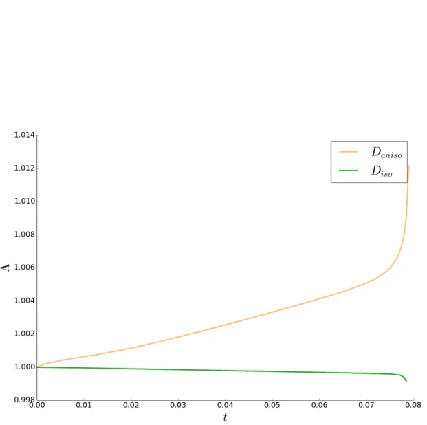
3.4 Comparison between the anisotropic and isotropic velocities . . . 84
4 Multiple Junctions 101 4.1 Statics of the polycrystal . . . 101
4.2 Dynamics of the polycrystal . . . 107
4.3 The Grim Reaper test case . . . 108
4.4 Torque effects on a triple junction . . . 124
5 Applications 135 5.1 Applied test configurations for “twins” . . . 135
5.2 Purely heterogeneous 2D microstructures . . . 142
5.3 Homogeneously anisotropic 2D microstructures . . . 161
Perspectives 171
Appendices 185
Chapter 1
Context
In order to begin modeling physical phenomena, the underlying experimental observations and the state of the art of the domain must first be understood. The following sections are devoted to not only describing the natural processes of interest in this work but also defining the terminology that is given to these mechanisms so that readers may become aware of the current state of knowledge of the field if they are not already. However, the domain of “physical metallurgy”, which studies the physical properties of metals and their alloys, is vast. The goal of these sections is not to give a comprehensive view of this subject, but rather to introduce the natural systems at work during the heating and cooling of a certain class of metals and alloys. The class of alloys that are of interest here, at least in an initial approach, is that of “monophase” polycrystals as opposed to “multiphase” polycrystals or single crystals in general. Monophase systems describe often idealized versions of reality. Even so, under certain conditions of temperature, composition and thermo-mechanical history, a significant number of metallic materials are in a monophase state. Thus, monophase materials are chosen as the main topic of this work. Once the physical aspects of annealing have been outlined, a certain number of models for reproducing these mechanisms that have been developed in the literature will be described and analyzed.
1.1
The microstructures of monophase metallic
ma-terials.
Although the etymology of the term “crystal” can be traced back to the ancient Greeks, the first indirect measurements of the atomic structure of a crystal can be placed in 1912 in the work by Friedrich, Knipping and Laue who made the first observations of the interaction between X-rays and structured matter [44]. Their findings, on the diffraction of X-rays through certain materials, gave birth to the field of crystallography and thus our modern notion of what is a crystal [45].
Definition 1. A crystal structure is a state of matter characterized by the regular ar-rangement of a unit motif over relatively large atomic distances.
In order to clarify this definition, some of the terminology must first be detailed. First, the “unit motif” referred to can be any structuration of the atomic scale. As such, this unit structure can be itself an atom, a molecule, a group of atoms, a protein, the motif of a polymer, etc. The notion of “regular arrangement” holds within it the notion of a symmetry of the whole structure. This symmetry can be described as translational, where the unit motif may repeat itself periodically in given directions, or rotational, where the crystal may look exactly the same in certain directions, or even mirror, where the structure might be indistinguishable from the mirror image of itself. “Large” atomic distances are distances that are orders of magnitude larger than the characteristic size of the unit structure. This means that the crystallinity of the matter is not just a local characteristic but a global one. Figure 1.1 is a diagram of a 2D crystal lattice where the unit structure is the circle and the various symmetries are portrayed as operations on the lattice that leave the entire structure unchanged. These symmetries are in reality what differentiates crystal structures from each other.
Figure 1.1: 2D crystal lattice diagram of translational, rotational and mirror symmetries.
Almost the entirety of stable metallic matter comes in a crystal state. This means that the “natural”, at least for the conditions of pressure and temperature found commonly on earth, solid state of a metallic material is structured periodically. However, this symmetric ordering at the atomic/“super-atomic” scale does not necessarily extend all the way to the macroscopic scale except in so-called single crystal materials. There is notably one intermediate scale of great interest for the material properties of metals and alloys which is called the microstructure of the material [46]. This scale of the material, ranging
potentially from a few nanometres to the millimeter, can be seen as a composition of different crystallites or grains, regions of space with the structural periodicity characteristic of a crystal, stuck together to form the bulk of the material called a polycrystal. Figure 1.2 illustrates this concept by considering different regions of space made out of the same crystal structures oriented in different manners.
Figure 1.2: A 2D monophase microstructure diagram where the grains with the same orientation are colored the same way (the spatial scale is not representative).
Indeed, the Figure 1.2 does not quite do justice to the richness of the most complex real microstructures which might be composed of different phases, regions where the chem-ical composition and crystal structure might change. However, considering “monophase” systems allow us to consider materials made up of one phase, and therefore one crystal structure, and as such operate in this simplistic view of the polycrystal microstructure. Even so, certain metallic alloys, such as Inconel R 718, a nickel based superalloy, can be
found in this monophase form as shown in Figure 1.3 under certain conditions. Some-times, nickel based superalloys are actually processed in such a monophase state during the forging process.
However, even as simple as one might want to consider monophase polycrystals, they come with their own complex features. These objects can be classified as crystallographic defects and constitute deviations from the perfectly periodic crystal structure. These distortions come in three large geometric classes:
Point Defects associated to missing or extraneous atoms in the lattice arrangement gen-erating a local disordering of the atomic structure.
Figure 1.3: Electron Backscattered Diffraction (EBSD) map of a monophase Inconel R 718
sample, provided by Alexis Nicola¨y [47], in which the twin boundaries are shown in red, the general grain boundaries are in black and the crystallites are colored according to their crystallographic orientations.
Line Defects of which the largest group are called dislocations, which are locally struc-tured distorsions in the crystal structure that generate elastic stress fields in the nearby lattice.
Surface Defects the most prominent example being grain boundaries, structures created when two crystallites with different crystallographic orientations meet.
Of course, the examples given are the most commonly discussed objects in the literature and do not constitute an exhaustive list. For example, one could classify a triple line, the meeting of three grain boundaries in three dimensions, as a line defect that does not adhere to a dislocation type structure. Figure 1.4 illustrates examples of these of defects projected into 2D planes of a crystal.
These defects and their distributions play a large role in the final properties of metallic materials. Their concentration is the metric by which a polycrystal’s deviation from a perfect crystal structure is quantified both globally and locally. For example, dislocation densities in polycrystals are directly related to work hardening, the phenomenon by which a metallic material becomes harder as it is deformed [46]. Grain boundaries implicitly define the size of the grains in a material, the distribution of which can be related to the yield strength of polycrystalline matter by the Hall-Petch effect [48]. As such, a monophase material’s microstructure can truly be characterized by the spatial distribution of crystallographic defects.
Figure 1.4: Diagram of a vacancy, a dislocation and a grain boundary in two dimensions where the neighboring units are in orange and the matrix is in blue while the geometric aspect of the defect is in black.
Taking a more quantitative view of the microstructure, we can attempt to define the energy of a defect as follows
Definition 2. The energy of a crystallographic defect is the work one must furnish in order to insert this defect into an initially defect-free crystal structure.
Therefore, defining the ground state energy of a certain mass of perfect crystal G0 and potentially calculating the energy of the same mass of crystal containing one defect Gd, one may calculate the energy of the given defect ℵd as
ℵd= Gd− G0 (1.1) While this definition is perfectly usable for point defects, the notion of an energy density must be used for higher dimensional geometric defects. Indeed, line and surface defects are ill-quantifiable in terms of number because they span certain regions of physical space. As such, we may define more precisely the energy density ρd of a line or surface defect as
ρd= lim µ→0
Gd− G0
µ (1.2)
where µ is the spatial measure of the defect (length if it spans a line and area if it spans a surface). As such, one has the necessary notions to define the total energy of a monophase polycrystal microstructure G as
G = G0+ X p∈P ℵp+ X l∈L Z l ρldµl+ X s∈S Z s ρsdµs (1.3)
where P is the set of all point defects, L is the set of all line defects and S is the set of all surface defects. Now even though most of the symbols in equation (1.3), have not yet been properly defined, it serves the symbolic purpose to define the total energy of the microstructure in terms of a sum of energies of individual defects.
However, there is a zoology of sub-classifications of all kinds of defects. These classes may or may not follow the geometric categorization given here and can be broken down into more and more specific sub-groups. For example, point defects can be decomposed into vacancies, substitutional defects and interstitial defects. The interstitial group may be sub-divided into interstitials that are made of different types of atoms present in the nominal composition of the material or impurities that can be found in small quantities. Dislocations can, schematically, be found in two extreme flavours, edge and screw. Each of these groups can be hierarchically divided into multitudes of subgroups and so on. Ultimately, the granularity with which one describes these defects is not so much a physical choice but a modeling one. The sub-classification of these defects that one might use is thus a reflection of both the model’s scale and its complexity.
For example, if one considers a model that represents all grain boundaries as equivalent objects with the same properties, then this model would be incapable of differentiating between the behaviors of physically different interfaces. Yet, in the most general cases and close to the atomic scale, grain boundaries can be parameterized by thirteen independent structural parameters [49]. In this work the goal is to generate a model capable of simu-lating annealing twin boundaries as distinct objects from other types of grain boundaries. As such, the first question to ask in this situation is what level of detail does our model need in the description of the twin boundary? A reformulation of the question is what is the minimum set of structural parameters of the grain boundary such that the annealing twins can be successfully differentiated, at the scale of the polycrystal, from other grain boundaries?
Taking into account the fact that target model is a microstructural model, and not atomic or macroscopic, and that the properties of the grain boundaries must be measurable using conventional experimental microscopy techniques, the five parameter description of the grain boundary [49] is chosen.
Definition 3. The grain boundary space B can be parameterized by five independent pa-rameters:
• three related to the misorientation of the grains on either side of the boundary, • and two related to the inclination of the boundary plane.
Figure 1.5 illustrates the concept behind the five parameter description of the grain boundary in 3D. Indeed, the misorientation of the boundary is defined by both the orien-tation relationship of both neighboring grains and the symmetries of the base crystal. The inclination of the boundary is then defined more locally by following the geometry of the
Figure 1.5: 3D diagram of the five parameter description of the grain boundary Γ between grains G1 and G2 with respective crystal orientations O1 and O2 with crystal frames C1 and C2 generating a misorientation M12 and an inclination vector n21 in the Ω space equipped with a reference frame R.
interface with respect to the neighboring crystal structures. However, in order to introduce these notions properly, their mathematical representations must be first understood [49]. Let Ω ⊂ R3 be the domain of the microstructure equipped with a reference frame R ∈ R, with R the set of all possible frames of R3
R = {{x0, x1, x2} ∈ (R3)3|{x0, x1, x2} is an orthonormal basis of R3} (1.4) (SO(3), ·) is the special orthogonal group equipped with its classical group operation. The elements of this group can be represented by rotations in R3. Given an element M ∈ SO(3), its action on any set of vectors {xi=1,...,n} ∈ (R3)n conserves both lengths, angles and orientations between these vectors. As such, the action of M on any frame in R is also a frame and thus R is closed under the action of any element of SO(3)
M ∈ SO(3) =⇒ M : R → R
Any crystal structure can be attributed a crystal frame C that serves to parametrize the lattice positions of its unit motifs. However, in a polycrystal, the crystal frames of each crystallite are all potentially oriented differently from each other in space. As such, given the reference frame R and the crystal frame of any grain Cn∈ R one can define the orientation of the grain as follows
of SO(3) such that
Cn= On(R) (1.5) with R the reference frame.
However, this definition does not ensure the uniqueness of the description of the ori-entation of a grain because of the symmetries of the crystal structure. These symmetries naturally define a crystallographic equivalence relation ≡cry between frames in R. Let S be the rotational symmetry group of the crystal defined as
S = {s ∈ SO(3)|s(C) ≡cry C, ∀C ∈ R}
As such, the crystallographic equivalence set [C] of a frame C ∈ R is the set of frames defined as
[C] = {s(C), s ∈ S}
Analogously, using the group operation · on SO(3), the equivalence set [O] of a given grain orientation O ∈ SO(3) can be defined as
[O] = {(s · O), s ∈ S} (1.6)
This means that each crystallographic orientation has as many representations as there are rotational symmetries in the symmetry group of the crystal. This fact is important because if we would like to define the orientation relationship Dnm between two grains accepting orientations On and Om as
Dnm = On· Om−1 (1.7)
we come to the conclusion that this object is not unique and admits its own crystallo-graphic equivalence set [Dnm] as
[Dnm] = {(s · On) · (s0· Om)−1, (s, s0) ∈ S} (1.8)
whose size is actually the number of rotational symmetries squared. From a compu-tational point of view, this set is rather cumbersome to deal with in that it contains, by definition, the same information many times over. One would much rather deal with one representative object of the set than all of them. However, any choice of an individual orientation relationship from the equivalence set must be made in a systematic manner such that the same representative is chosen each time the same set is considered.
Definition 5. A fundamentalization operation Y is a function that takes a set of objects A and returns one representative of the set a such that each time the same set is given, the same representative is chosen
Y : P(V ) → V
A → a ∈ A (1.9)
where P(V ) is the power set of a set V .
As such, for a given choice of fundamentalization operation Y on the base set SO(3) we can define the misorientation as
Definition 6. The misorientation Mnm between two grains accepting orientations On and Om respectively is an element of SO(3) such that
Mnm = Y ([Dnm]) (1.10) Corollary 1. The misorientation of a grain boundary is the misorientation between its neighboring grains.
Therefore, the misorientation of a grain boundary contains the information regarding the bicrystallography of its constitutive grains. It does so in a unique and systematic way. Also, being elements of SO(3) the misorientations can be parameterized by three independent parameters, three Euler angles for instance.
In practice, the orientation relationships Dnm in an equivalence class [Dnm] can be represented by angle-axis pairs [(θnm, anm)] where the θnm parameter is the rotation angle and the unitary vector anm is the axis around which one rotates. This description is not very useful from a computational point of view where one might need to combine different rotations together. For this purpose, unit quaternions
qnm = (cos(θnm), sin(θnm)a1, sin(θnm)a2, sin(θnm)a3)
are actually easier to use. The quaternions have a natural Hamiltonian algebra which make the computation of subsequent rotation much more efficient than other represen-tations. Also, the fundamentalization operation for the quaternion representation of the misorientation mnm can be expressed as the unique quaternion
mnm∈ {q ∈ [qnm] | ∀u ∈ [qnm], q0 ≥ u0} ∩ {q ∈ [qnm] | q0 > q1 > q2 > q3} which is relatively efficiently computed in a numerical setting.
At the mesoscopic scale, the information regarding the inclination of the grain bound-ary is contained in the normal vector n to the interface at each point of the interface.
However, the normal vector represented in the reference frame R gives no information about the crystal planes of the grain boundary. The normal vector only describes the atomic planes when it is expressed in the crystal reference frames of the neighboring grains
(nn, nm) = (On−1n, O −1
m n), (1.11)
which holds redundant information when considered with the misorientation Mnm
(nn, nm) = (O−1n n, M −1 nmO
−1
n n) = (nn, Mnm−1nn), (1.12) where the orientations act on vectors with the classic operation of SO(3). Therefore the inclination of the grain boundary, when put into relation with the misorientation, is fully characterized by the inclination of the boundary plane in the reference grain, nn in this case. Normalizing this vector, it becomes unique and can thus be parameterized by 3 − 1 = 2 parameters, two angles in spherical coordinates for example.
As such, a grain boundary Bnm can be characterized by a tuple
Bnm= (Mnm, nn) (1.13) containing the misorientation and the inclination.
As such, when dealing with the parameterization of grain boundaries, extreme care must be given to respecting this equivalence relation ≡cry. In this sense, the choice of equivalent orientation for both grains must not influence any physical property one might wish to calculate.
In fact, in this work, there are only two physical quantities of interest for the dynamics of grain boundaries during annealing which are the energy density γ and the mobility µ both maps from B to R+ [32].
However, the measurement of the actual maps γ and µ are still open lines of inquiry that are studied by both experimental investigations [37–39] and numerical calculations [40,42, 50,51]. What is striking in the results of these studies is the dependence of both the energy density and the mobility of a grain boundary on its five parameter characterization Bnm. Indeed, these quantities vary by orders of magnitude, in the same material, at different points of the five parameter grain boundary space [51]. It is hypothesized that these two properties of grain boundaries might control both the dynamics and statics of grain boundaries at the scale of the microstructure. For example, in [52] the faceting behavior of boundaries are related to the evolution of γ function as the temperature changes. However, all analytical approaches to define a function of the entire grain boundary space that could describe the energy density, for example, have been either inconclusive or very new and untested [50, 51]. The most successful, and perhaps simplest, such analytical function is perhaps the Read-Shockley model for grain boundary energies [36] based on a dislocation type reduction of the grain boundary. This model does not cover the entire space of grain boundaries but only those with the “smallest” relative misorientations, i.e. the “low angle”
grain boundary subspace. This model is not of particular use in what concerns the twin boundary which can be classified as a “high angle” grain boundary.
Definition 7. A twin orientation relationship between two crystal orientations is one which creates an additional bicrystal mirror symmetry.
Given that the most common Nickel based superalloys have face centered cubic (FCC) crystal structures, the twin boundary in this context can also be more specifically de-scribed.
Corollary 2. In a FCC crystallographic structure, twin boundary is a grain boundary that accepts an orientation relationship between its neighboring grains described as a 60◦ rotation around a h111i axis common to both grains.
The particular bicrystallography of the twin orientation relationship accepts many crystallographically equivalent representations. Another noteworthy one is
Corollary 3. Two FCC crystallites in a twin orientation relationship can have their orientations transformed one into the other after applying a mirror symmetry with respect to their common (111) plane.
Therefore, an annealing twin is classified as such only with respect to its misorientation. One may also further subdivide the annealing twin class of boundaries into two groups that depend only on the inclination of the boundary
Corollary 4. A coherent twin boundary is a twin boundary whose boundary plane is the (111) plane that both grains share while an incoherent twin boundary is any other twin boundary.
As such, the twin boundaries are actually just a subspace BT of the total boundary space B. The coherent twin boundary is one point in tcoh ∈ BT while the space of inco-herent twin boundaries is the complement of tcoh with respect to BT. Figure 1.6 depicts 2D representations of both types of twins in FCC lattices. Even though these singu-lar boundaries generate more bicrystallographic symmetries than a more general grain boundary, this is not what generates the interest surrounding them. Their preponderance in processed microstructures of certain metallic materials (low to medium stacking fault energy materials to be precise) has long remained a mystery in the physical metallurgy community [32, 49].
The working hypothesis for the disproportionate amount of annealing twin boundaries in material microstructures is related to their relatively low energy density [32]. Indeed, in all atomistic calculations of the energy density of grain boundaries in low stacking fault energy materials, the coherent twin boundary is often computed to have an order of magnitude lower energy density than other more general boundaries [40]. The idea is that, statistically, since the energy of the coherent twin boundary is so low, the coherent
(a) coherent (b) incoherent
Figure 1.6: Diagrams of 2D projections of twin grain boundaries for an FCC structure viewed along h110i in the coherent (1.6a) and incoherent (1.6b) cases.
twin boundary is thus favoured over other grain boundaries as the microstructure evolves during processing. Nickel is a low to medium stacking fault energy material and thus most nickel based superalloys are as well. Indeed, as is shown in Figure 1.3, a great number of nickel based superalloys are subject to larger amounts of twin boundaries as compared to other types of grain boundaries. Even so, the distinction between coherent and incoherent twin boundaries is an important one. The same atomistic simulation investigations that show the coherent twin boundary as having very low energy density in pure nickel for example [40] also show that incoherent twin boundaries may have energy densities of the same order as other more general boundaries. Thus, the energetic singularity of the coherent twin boundary does not necessarily extend to the entire twin boundary space BT. Thus a model capable of predicting the behavior of twin boundaries must not only be able to differentiate boundaries with respect to their misorientations but also with respect to their inclinations.
1.2
The phenomenology of annealing processes
Now that the general structures present at the microstructural level in monophase poly-crystal materials have been enumerated, one may consider the more dynamic aspects of the microstructure during annealing. For the monophase polycrystal, there are three main processes at work during the annealing of these types of materials after deformation: re-covery, recrystallization and grain growth [32]. A brief overview of each before looking at how the twin boundaries evolve during these processes will be given here.
Definition 8. Recovery is a process by which, at high enough temperatures, both point defects and line defects become more dynamic in the microstructure, interact with each other and anihilate or evolve to create more structured configurations of lower energy.
As such, recovery is often associated with the evolution of dislocations since these are the easiest line defects to observe experimentally. Indeed, in a metallic microstructure where dislocations and point defect have been inserted, either by cold work, hot defor-mation, irradiation or some other energy injective approach, these defects become mobile enough to start making lower energy configurations at high enough temperatures. The most relevant example of recovery is the process by which tangles of dislocations, created often during cold working, reconfigure into what are called “subgrain” boundary struc-tures. Seemingly initially randomly dispersed dislocations in a grain may, under the effect of temperature, evolve into a regular cellular structure within the grain. These “sub-grains” are often devoid of dislocations in their interior with very high concentrations in their boundaries. Of course, the temperatures at which recovery starts to become visible and the extent to which a microstructure may recover depend heavily on the aptitude of the defects to move as well as their density. Once again, the parameter of primary importance has been shown to be the stacking fault energy of the material, where low stacking fault energy metallic materials generate very little recovery while high stacking fault energy materials tend to use recovery as the primary mechanism for stabilizing their microstructures [32]. In this work, concentrating on low to medium stacking fault en-ergy materials such as nickel based superalloys, recovery is not the primary mechanism of interest.
Definition 9. Recrystallization is the mechanism by which defect-heavy microstructures create new grains that are almost completely defect free and subsequently evolve, favouring the new crystallites.
The primary mechanism of stabilizing the microstructure in low stacking fault energy materials is mostly reported to be discontinuous recrystallization. This phenomenon is of-ten divided into two phases: nucleation and growth, as schematically represented in Figure 1.7. In very defect heavy microstructures, nucleation is the process by which a reconfigu-ration at the atomic level gives rise to a new crystallite with its own crystal orientation. This new grain has a rather “perfect” crystal structure and its bulk is thus favoured over its defect heavy surroundings. As such, the new grain grows into the surrounding matrix reconfiguring the largely distorted crystal structure into a much more regular atomic ar-rangement. The reason for which the microstructure must be concentrated in defects is that the appearance of a new grain costs a considerable amount of energy due to the new interface that is created. This energy must be over-balanced by the amount of defects de-stroyed during the process for the nucleation step to be energetically favourable and thus drive the microstructure to a more stable state. There exists thus a competition between the energy contained in the defects per volume area of the old microstructure as compared with the interface energy created when creating new grain boundaries analogous to phase transformations. However, the growth that can be observed during recrystallization is differentiated from the so-called process called grain growth.
Figure 1.7: Diagram of nucleation and growth during the discontinuous recrystallization process where only the dislocations and grain boundaries are drawn. The colors help visualize the different grains.
Definition 10. Grain growth is the process by which a microstructure, relatively free of point and line defects, becomes more stable by having the grains grow.
Indeed, a microstructure that has very few point and line defects but potentially many grain boundaries has only one avenue of stabilization which is to reduce the energetic con-tribution of its interfaces. The grains thus grow, not under the influence of reorganizing a defect heavy crystallite, but in order to reduce the quantity and energy density of inter-faces in the material. In order to do so, the grain boundaries tend to exhibit properties of curvature flow, by which the polycrystal interfaces evolve in the opposite direction to their maximal curvatures. As such, the curvature of the grain boundaries is directly related to the driving forces of their dynamics. Grain growth is a process that may follow recrystal-lization once the most defect heavy grains have disappeared. Possibly the most reliable way to differentiate in between these two growth mechanisms is the characteristic driving force magnitude and time scales that one may attribute to each. While recrystallization processes can be very “fast”, lasting only of the order of a hundred seconds in some cases, in comparison, grain growth is considered to be very “slow”, lasting orders of hours in order to observe comparable increases in grain size in the microstructure , in metallic ma-terials [32]. However, what the grain growth mechanism lacks in effectiveness it makes up for in ubiquity. Any polycrystal, submitted to sufficient temperature conditions, will un-dergo a grain growth mechanism. Often this growth is detrimental to target macroscopic mechanical properties in industrial processes however can be beneficial for materials that require large grains such as materials with specific electromagnetic properties.
These three microstructural evolution mechanisms find their origin in the same place. Indeed, recovery, recrystallization and grain growth are processes that reorganize atomic arrangements in order to bring the material closer to its ground state, the monocrystal. The emergence of these phenomena at the microstructural level thus depend on the defect structure of the material itself. Even so, the temperature of the material plays a non-trivial role. In order to operate these processes at the atomic level, certain energetic barriers to
the movement of units in the lattice must be surmounted [53]. Increase in temperature serves to increase the vibrational energy of the crystal lattice and thus enables these barriers to be negotiated. Exactly which temperatures must be provided depend on the energetic barriers to each process which in turn depend on the metallic materials structural properties (composition, crystallographic structure, etc.). Thus, these annealing processes fall under the more general class of thermally activated phenomena.
Given that the defect distribution in a polycrystal is heavily affected by these phe-nomena, as a subset, the twin boundary distribution also evolves considerably during annealing. So much so that a another subclass of twin had to be defined.
Definition 11. An annealing twin, and associated boundary, is a twin that has appeared during the annealing process.
Annealing twins are distinct from deformation twins which appear during the defor-mation process [46]. In this work, defordefor-mation twins will be set aside and only annealing twins and their boundaries will be considered.
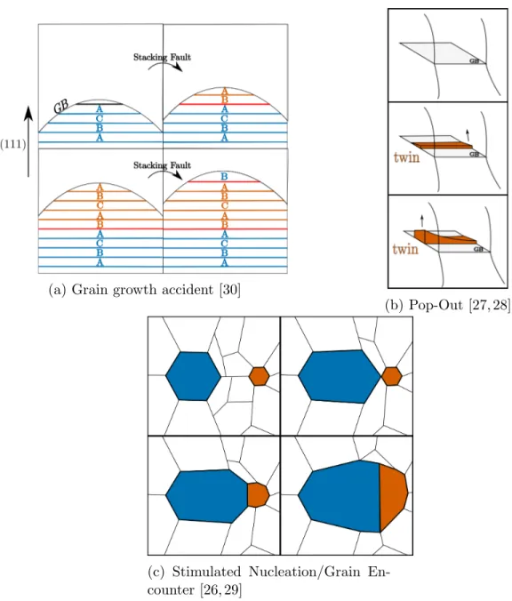
Given the definition of an annealing twin boundary, they must appear and evolve during the annealing process thus subsequently during either the recrystallization or grain growth steps. Exactly how they behave during these processes has been the subject of many experimental investigations, [18–25, 54–57] to only cite a few, conducted since their first observation in [58]. Indeed, the mechanism by which these boundaries appear during annealing is the subject of much contention in the literature [26–30]. Globally, three principle mechanisms have been proposed which are illustrated in Figure 1.8.
The most common mechanism cited in the literature is the “Grain Growth Accident” mechanism by which a stacking fault is created at a moving (111) boundary of a growing grain [30]. During recrystallization or grain growth, atoms move across grain boundaries effectively switching from one grain to another. There can be mistakes in the placement of these new atoms in a growing grain. This mistake or accident in the configuration of incoming atoms can lead to the beginning of a stacking fault which propagates itself using the incoming atoms, arranging them in a twin configuration. In low stacking fault energy materials, the new boundary is relatively stable due to the fact that it is a coherent twin boundary and thus of low energy. As such, a new twin oriented crystallite is nucleated at a moving grain boundary and continues to grow where its “parent” would have grown before.
Another mechanism called “Grain Boundary Dissociation” [28] or “Pop-Out” [27] de-scribed in different papers at different times but ultimately remaining the same mechanism is a close contender. In this case, a wave of partial dislocations (i.e. an incoherent twin boundary) nucleates at a grain boundary for a given reason (lower energy resulting bound-aries, encounter of special dislocation structure, etc...) and propagates itself within the grain, reorienting a space within the crystallite into a twin configuration. This is consid-ered energetically favorable since most of the boundary length created is coherent. The twin can grow as well if the boundaries with which it is in contact are moving. At first
(a) Grain growth accident [30]
(b) Pop-Out [27, 28]
(c) Stimulated Nucleation/Grain En-counter [26, 29]
Figure 1.9: Diagram of the phenomenological evolution of annealing twin boundary den-sities during recrystallization and subsequent grain growth adapted from [60]
glance, it seems like a peculiar way for a new orientation to appear. The twin orientation actually propagates into a grain relatively devoid of defects in order to create a sort of lamellar structure. However, experimentally observed morphologies tend to corroborate this type of anatomy of a twinned grain.
The final identified mechanism is a “Stimulated” twinning/Grain Encounter [26, 29] in which a growing grain encounters its twin orientation in the surrounding polycrystal matrix. Upon meeting this twin “nucleus”, the original grain’s growth is hampered by a sort of orientation pinning while the twin grain’s growth is stimulated. The twin then grows out from the original grain’s boundary much as a new nucleated grain. However, not much interest is afforded to this explanation. The probability of a given grain encountering another grain with a twin orientation cannot account for the abundance of twin boundaries observed in experimental microstructures [59].
Putting aside the mechanisms of formation of twin boundaries, much can be said about the statistical evolution of twin boundaries in polycrystal microstructures. Indeed, there is an abundance of investigations into the evolution of twin densities during annealing processes [21, 54–57, 59, 60]. Even so, given the diversity of thermomechanical conditions and materials for which these studies are conducted, general conclusions are difficult to extract from all the data. Of particular interest here is the work of [60] in pure nickel and nickel based superalloys.
The work in [60] can be partially summarized in the diagram shown in Figure 1.9. The figure schematically represents the evolution of twin boundary density, the length of the twin boundaries per unit area in a micrograph, in the microstructure during recrys-tallization and subsequent grain growth. The density is shown to increase quickly during
recrystallization where it is hypothesized most of the twins are nucleated. During grain growth, the twin density decreases at a much slower rate. It is shown that many of the grains nucleated during the recrystallization process already contain a multitude of twin boundaries. As such, during the growth of these grains, the twin boundaries follow the fate of their “parent” grains so to speak. If a new grain containing twin boundaries grows, the twin boundary grows as well and if the grain shrinks, so too does its twin boundary. As such, since globally the amount of boundary decreases during grain growth, so too does the twin density. However, given the large proportion of twinned grains, it seems that annealing processes would favour the persistence of twin boundaries in the microstructure unless new twins are nucleated during the grain growth process. In [21] the authors show that even during grain growth it was possible to nucleate twins, even if it was very rare. This nucleation during grain growth only occurred at multiple junctions. However, this twin boundary nucleation during grain growth is much too sporadic to account for the orders of magnitude of twin densities observed experimentally.
In any case, these observations are in accordance with the abnormally twinned mi-crostructures one obtains in “multi-pass” forging operations [31]. In these processes one might deform the material at ambient temperature than anneal it for a very short time and then repeat the process multiple times. The microstructures of these materials are often the fruit of recrystallization processes where grains grow under the influence of strain induced grain boundary migration (SIBM). SIBM is a phenomenon where boundaries al-ready present in the microstructure (i.e. no nucleation step) migrate in order to minimize the stored energy due to dislocations. As such, the heterogeneity of dislocation distribution in the polycrystal is the main driving force for the grain boundary migration.
Even if this sort of mean value accounting of twin density and its evolution is vital to the understanding of the evolution of twins, it does not illustrate the singular morphology of the twin boundary. Indeed, twins are often separated by a combination of coherent and incoherent boundaries with the same configurations being oddly widespread in real microstructures. Figure 1.10 illustrates many of the twin configurations one may find in 2D micrographs schematically. This illustration is directly confirmed by many of the twin boundaries that can be observed in Figure 1.3 and Figure 1.11.
These morphologies become more convoluted however when looking at 3D microstruc-tures. Figure 1.12 shows the 3D reconstruction of a twinned grain taken from [59]. This Figure demonstrates that the 3D morphologies of annealing twins may be more compli-cated than what the 2D sections may suggest at first sight. These considerations become even more important when one studies twin related domains (TRDs) in engineered mi-crostructures [61, 62] where large portions of the microstructure can be considered to be one twinned grain. In any case, the straight coherent twin boundary seems to be dispro-portionally present in real microstructures which tends to support its supposed low energy density.
From a modeling perspective, what is clear from the above bibliography and Figure 1.11 is that one of the main aspects in explaining the behavior of these annealing twins, once
Figure 1.10: Diagram of 2D observed twin morphologies reproduced from [30]
Figure 1.11: Unpublished results of twin boundary evolution during an in-situ annealing series of a 304L steel. Twin boundaries are in red and more general boundaries are black.
Figure 1.12: 3D reconstruction of a twinned grain in a pure nickel microstructure using High Energy X-ray Diffraction Microscopy (HEDM) reproduced from [59]
they’ve appeared, is related to their special energy densities, specifically concerning the coherent twin boundary. Indeed, the hypothesis made in this work is that the energy density of the twin boundary is the first order property in explaining the behavior of this grain boundary during annealing. In summary, a physically based model capable of taking into account a twin boundary is a model that can account for a grain boundary energy density function γ(M, n), where (M, n) is the five parameter description of the grain boundary. Once this model is developed the boundary energy density should have characteristics that reproduce the behavior and morphologies of the twin boundaries.
1.3
Full field modeling approaches
The word model has been used thoroughly in this document. Even though most readers will have an intuitive understanding of the meaning, it may be helpful to give a simple definition.
Definition 12. A model is a simplified description, especially a mathematical one, of a system or process, to assist calculations and predictions (Oxford Dictionary).
As such, in the case of physical models, a model does not faithfully represent reality. Indeed, it is an approximation of reality that can be made richer by integrating more aspects of reality into it. In this sense, the quality of a model is based only on the predictions it is capable of making. Any mathematical model that is supposed to describe natural processes must be faithful to a certain number of observed phenomena in order to be useful. The best models are capable of predicting phenomena that have not yet been observed.
This definition gives rise to a spectrum of types of models ranging from very simple to deeply complex. The simple models are often easy to comprehend but have limited pre-dictive power. The more complex models tend to cover a much larger range of observable phenomena with more precision. Thus the process of enriching a model is that which takes a given representation for a given process and extends the applicability of it to a more diverse set of mechanisms. However, increasing the complexity of a system comes with a cost. The more complex a scheme the more difficult it is to extract a prediction from it. If the model is too complex to solve or to parameterize, it is of no practical use since no predictions can be made from it. As such, the enriching of any structure is a balancing act between incorporating the relevant aspects of reality while keeping the system tractable.
This line of thought has given rise to many different types of models with differing complexities and goals. Some terminology of particular interest is the distinction between mean field models and full field models.
Definition 13. Mean field models describe the behavior of statistical quantities of a system. Definition 14. Full field models describe the behavior of local quantities of a system.

![Figure 1.12: 3D reconstruction of a twinned grain in a pure nickel microstructure using High Energy X-ray Diffraction Microscopy (HEDM) reproduced from [59]](https://thumb-eu.123doks.com/thumbv2/123doknet/2829404.68284/36.918.290.693.704.966/figure-reconstruction-twinned-microstructure-energy-diffraction-microscopy-reproduced.webp)