Analytical and Finite Element Study of Residual Stresses in
the Transition Zone of Hydraulically Expanded
Tube-to-Tubesheet Joints
by
Mohammadhossein POURREZA KATIGARI
THESIS PRESENTED TO ÉCOLE DE TECHNOLOGIE SUPÉRIEURE IN
PARTIAL FULFILLMENT OF THE REQUIREMENTS FOR
A MASTER'S DEGREE WITH THESIS IN MECHANICAL ENGINEERING
M.A.Sc.
MONTREAL, MARCH 29TH, 2018
ÉCOLE DE TECHNOLOGIE SUPÉRIEURE
UNIVERSITÉ DU QUÉBEC
© Copyright reserved
It is forbidden to reproduce, save or share the content of this document either in whole or in parts. The reader who wishes to print or save this document on any media must first get the permission of the author.
BOARD OF EXAMINERS
THIS THESIS HAS BEEN EVALUATED BY THE FOLLOWING BOARD OF EXAMINERS
Mr. Hakim Bouzid, Thesis Supervisor
Mechanical Engineering Department at École de technologie supérieure
Vladimir Brailovsky, President of the Board of Examiners
Mechanical Engineering Department at École de technologie supérieure
Anh Dung Ngo, Member of the jury
Mechanical Engineering Department at École de technologie supérieure
THIS THESIS WAS PRESENTED AND DEFENDED
IN THE PRESENCE OF A BOARD OF EXAMINERS AND PUBLIC MARCH 19TH, 2018
ACKNOWLEDGMENT
I would like to express my appreciation to all those who provided me support on the way to complete this research. I give special gratitude to my professor, Dr. Hakim Bouzid, whose contribution of stimulating comments and encouragement through the learning process of this master research helped me come across many new findings. I had the opportunity of working under his supervision for about two years, and the implementation of this research project would not have been possible without his support.
My deepest gratitude is also due to the members of the examiners committee, Prof. Dr. Vladimir Brailovsky from the department of mechanical engineering, as the president of the Board of Examiners, and Prof. Dr. Anh Dung Ngo as a member of the jury from the department of mechanical engineering for their contribution and great suggestions.
Furthermore, I would also like to thank my wife, who was abundantly helpful and offered invaluable assistance and support throughout the different stages of my master’s degree.
ÉVALUATION ANALYTIQUE DES CONTRAINTES RÉSIDUELLES DANS LA ZONE DE TRANSITION D’UN JOINT DUDGEONNÉ
Mohammadhossein, POURREZA KATIGARI RÉSUMÉ
Le processus d'expansion des tubes a fait l'objet de nombreuses recherches au cours des années. La première étude menée par Oppenheimer (1927) a été consacrée à la technique de dudgeonnage des tubes par roulement mécanique. En fait, les études précédentes se sont surtout concentrées sur le procédé de fabrication de l'expansion du tube et peu d’attention à la défaillance de l’assemblage dudgeonné. En 1966, Toba A. a attiré l'attention des chercheurs sur le fait que les contraintes résiduelles dans la zone de transition du tube sont à l'origine du problème; les tubes présentent des fissures par corrosion sous contrainte. Plus tard en 1976, Krips et Podhorsky ont développé un modèle pour simuler la nouvelle méthode de dudgeonnage par pression hydraulique pour développer le tube qui présente plusieurs avantages par rapport au mandrinage par roulement. Ces améliorations sont la détermination précise de la pression d'expansion nécessaire et l'expansion uniforme de la zone d’expansion. Cependant, la nouvelle méthode a réduit le niveau des contraintes résiduelles de traction dans la zone de transition, lesquelles en milieu corrosif sont les facteurs principaux de la propagation des fissures et finalement la dégradation du joint dudgeonné. Par conséquent, l'analyse de cette zone fera l'objet de cette étude. Des modèles analytique et numérique par éléments finis seront développés pour évaluer les contraintes résiduelles en tenant en compte plusieurs facteurs impliqués dans l'expansion d’un tube. Il est important de noter que les facteurs tels que le durcissement par écrouissage et le retour plastique dans la zone de transition ne seront pas traités dans ce rapport.
L'étude commence par le développement d'un modèle analytique dans lequel s'applique la condition d’écoulement selon Von Mises pour un cylindre circulaire subissant une rotule plastique, lorsque soumise à un chargement axisymétrique. En fait, la pression d'expansion sera limitée afin d'éviter la déformation plastique de la plaque tubulaire, bien que son effet soit négligeable sur les contraintes de la zone de transition.
Le comportement du matériau est censé être élastique parfaitement plastique (EPP). Les résultats ont révélé que trois régions différentes dans la zone de transition du tube devraient être considérées: région en rotule plastique, région partiellement plastique et région élastique. Par conséquent, la théorie des poutres sur fondation élastique et la théorie de la plasticité seront appliquées pour déterminer les contraintes résiduelles dans les différentes régions. Le modèle analytique sera validé en comparant les résultats avec ceux obtenus par éléments finis sur ANSYS Workbench 16.2. Les résultats ont montré un bon accord entre ces deux méthodes, bien que certaines limitations doivent être envisagées afin de prédire des contraintes résiduelles analytiques fiables dans la zone transition.
Mots clés : Dudgeonnage du tube, dudgeonnage hydraulique, assemblage tubes-plaque à tubes, zone de transition, contraintes résiduelles.
ANALYTICAL EVALUATION OF RESIDUAL STRESSES IN THE TRANSITION ZONE OF HYDRAULICALLY EXPANDED TUBE-TO-TUBESHEET JOINTS
Mohammadhossein, POURREZA KATIGARI ABSTRACT
The process of tube expansion has been the subject of much research throughout the years. The first study conducted by Oppenheimer (1927) was dedicated to the mechanical rolling technique of expanding the tube. In fact, initial investigations were mainly concentrated on the manufacturing process of tube expansion, and no attention was paid to tube failure due to the other parameters arising in this process. In 1966, Toba A. alerted researchers to the fact that the highest residual stresses at the tube transition zone are the origin of tube failure, because they cause stress corrosion cracking. Later, in 1976, Krips and Podhorsky modeled the new hydraulic expansion method to expand the tube, which has several advantages in comparison with mechanical rolling. These improvements are the accurate determination of expansion pressure and the longitudinal uniform expansion.
This new method reduces the level of tensile residual stresses at the transition zone which, under a corrosive environment, are the main contributors to crack propagation and, ultimately, tube degradation. Therefore, the analytical and finite element analysis of this zone is the subject of this study. The evaluation of the residual stresses, taking into account as many factors as possible in tube expansion, is the objective of the study. It is worthy to note that influence factors such as tube strain hardening and reverse yielding in the transition zone are not part of this work.
The study begins with the development of an analytical model in which the Von Mises yield condition for a rigid-plastic circular cylindrical shell subjected to axially symmetric loading is considered. The expansion pressure level is limited in order to avoid the tubesheet plastic deformation, although its effect is not significant on the transition zone stresses.
The material behavior is assumed to be elastic perfectly plastic (EPP). The results disclosed that three different regions in the transition zone of the tube should be considered: full plastic, partial plastic and elastic regions. The elastic beam foundation theory and the plasticity theory are used to determine the residual stresses in these regions. The validation of the analytical model is conducted by comparing the results obtained with those of the finite element analysis using ANSYS Workbench 16.2. The results show a good agreement between the two models. Nonetheless, some limitations should be considered in order to obtain reliable analytical residual stresses at the transition zone of an expanded tube.
Keywords: Tube expansion, hydraulic expansion, tube to tubesheet joint, transition zone, residual stresses.
TABLE OF CONTENTS
Page
INTRODUCTION ...1
CHAPTER 1 CONNECTION OUTLINE ...5
1.1 Heat exchangers ...5
1.2 Shell and tube heat exchangers ...6
1.3 Tube to tubesheet joint ...7
1.4 Common expansion processes ...8
1.4.1 Mechanical rolling ... 9
1.4.2 Hydraulic expansion ... 10
1.4.3 Hybrid expansion ... 11
1.4.4 Explosive expansion ... 12
1.5 Hydraulic expansion principles ...12
1.6 Factors influencing on rigidity of tube to tubesheet connection ...14
1.6.1 Expansion pressure ... 15
1.6.2 Initial clearance ... 16
1.6.3 Residual stresses produced by expansion process ... 16
1.6.4 Contact pressure ... 17
1.6.5 Material properties of tube and tubesheet ... 18
1.6.6 Friction at the interface ... 18
1.6.7 Tube layout and expansion sequence ... 19
1.6.8 Operating conditions ... 20
1.7 Failure mechanisms in tube to tubesheet connection ...21
1.7.1 Residual stresses ... 22
1.7.2 Intergranular attack (IGA) ... 22
1.7.3 Stress corrosion cracking (SCC) ... 24
1.7.4 Fatigue or cyclic stresses ... 25
1.8 Determination of residual stresses in transition zone ...26
1.8.1 Analytical approach ... 27
1.8.2 Finite element analysis ... 27
CHAPTER 2 LITERATURE REVIEW ...29
2.1 Introduction ...29
2.2 Experimental approach ...30
2.2.1 Comments and conclusion ... 39
2.3 Analytical approach ...40
2.3.1 Comments and conclusion ... 45
2.4 Finite element (numerical) approach ...46
2.4.1 Comments and conclusion ... .55
CHAPTER 3 ANALYTICAL MODELING OF HYDRAULICALLY
EXPANDED TUBE TO TUBESHEET CONNECTION ...57
3.1 Introduction ...57
3.2 Analytical model of the expansion zone ...58
3.2.1 Expansion without tubesheet plastic deformation ... 58
3.2.1.1 Tube elastic deformation ... 60
3.2.1.2 Tube elasto-plastic deformation ... 60
3.2.1.3 Tubesheet elastic deformation ... 61
3.2.1.4 Tubesheet plastic deformation ... 62
3.2.2 Unloading of expansion zone... 63
3.3 Analytical model of the transition zone ...63
3.3.1 Stresses during loading in the transition zone... 63
3.3.1.1 Stresses analysis of the full plastic region ... 64
3.3.1.2 Stresses analysis of the elastic region ... 68
3.3.2 Unloading of the plastic zone under elastic recovery ... 71
CHAPTER 4 FINITE ELEMENT MODELING OF HYDRAULICALLY EXPANDED TUBE TO TUBESHEET CONNECTION ...77
4.1 Introduction ...77
4.2 Tube to tubesheet model ...78
4.2.1 Nonlinearities associated with joint analysis ... 79
4.2.2 Elements and mesh ... 81
4.2.3 Contact surface and friction modeling ... 83
4.2.4 Constraints and loading... 84
CHAPTER 5 RESULTS AND DISCUSSIONS ...85
5.1 Introduction ...85
5.2 Case without reverse yielding of expansion zone ...85
5.2.1 Pressure loading ... 85
5.2.2 Pressure unloading ... 88
5.3 Pressure loading with reverse yielding case ...91
5.3.1 Pressure loading ... 91
5.3.2 Pressure unloading ... 94
CONCLUSION ...97
FUTURE WORK ...99
APPENDIX I MATLAB PROGRAM TO CALCULATE RESIDUAL STRESSES AT TRANSITION ZONE ...101
APPENDIX II ANSYS PROGRAM TO DETERMINE THE RESIDUAL STRESSES AT THE TRANSITION ZONE OF CASE 1...107
APPENDIX III ANSYS PROGRAM TO DETERMINE THE RESIDUAL
STRESSES AT THE TRANSITION ZONE OF CASE 2...123 BIBLIOGRAPHY ...139
LIST OF TABLES
Page
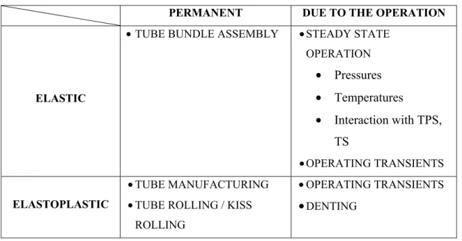
Table 2.1 Origin and type of stresses in the transition zone ...37 Table 4.1 Geometry and mechanical properties ...79
LIST OF FIGURES
Page
Figure 1.1 Shell and tube heat exchangers ...7
Figure 1.2 Tube expansion ...8
Figure 1.3 Mechanical rollers ...9
Figure 1.4 Diagram of the tube expansion installation ...11
Figure 1.5 Schematic of hyadraulic expansion process ...11
Figure 1.6 Plugs installation in explosive expansion ...13
Figure 1.7 Hydraulic expansion steps ...14
Figure 1.8 Influence of friction and radial clearance on interfacial contact stress ...19
Figure 1.9 Tube square and triangular layouts ...20
Figure 1.10 Tubesheet different thermal zones ...21
Figure 1.11 Example of degradation mechanisms of tube ...22
Figure 1.12 Intergranular attack at tube ID (Photo 2MA0270, Mag: 500X, unetched)…. ...23
Figure 1.13 Cracks in tube in the immediate vicinity of transition zone ...24
Figure 1.14 Three phases of crack growth, Paris-Erdogan's Law ...26
Figure 1.15 ANSYS 3D model of tube to tubesheet connection ...28
Figure 2.1 Holding force due to shrink fit alone in relation to plate thickness ...31
Figure 2.2 Specimen 5 (back) after expanding ...33
Figure 2.3 Comparison between test results and Table A-2 ...38
Figure 2.4 Experimental friction test set-up ...40
Figure 2.6 Schematic diagram and finite element mesh configurations of
a tube with an inner surface crack ...52
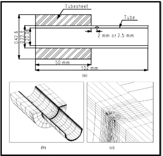
Figure 2.7 Model geometry and dimensions in mm ...53
Figure 2.8 a) Equivalent sleeve joint model and b) FE mesh for the grooved joint ...54
Figure 3.1 Expansion pressure diagram ...59
Figure 3.2 Schematic of different regions in transition zone ...64
Figure 3.3 Cylindrical shell with ring load ...66
Figure 3.4 Interaction curves ...68
Figure 3.5 Semi-infinite beam with bending moment and force ...70
Figure 3.6 External pressure on long thin-walled cylindrical shell ...71
Figure 3.7 Stresses and displacement in a long thin-walled cylindrical shell subjected to a band pressure ...72
Figure 4.1 Symmetric 3D model of tube to tubesheet connection ...78
Figure 4.2 Tube material stress-strain curve ...80
Figure 4.3 SOLID186 Homogeneous Structural Solid Geometry ...81
Figure 4.4 CONTA174 Geometry ...82
Figure 4.5 Mesh pattern of model ...83
Figure 5.1 Schematic of plasticity in tube when tube touches the tubesheet ...86
Figure 5.2 Schematic of plasticity in tube at maximum expansion pressure ...87
Figure 5.3 Comparison of stresses at tube inner surface at maximum expansion pressure ...89
Figure 5.4 Comparison of stresses at tube outer surface at maximum expansion pressure ...89
Figure 5.5 Comparison of stresses at tube inner surface during unloading ...90
Figure 5.6 Comparison of stresses at tube outer surface during unloading ...90
Figure 5.8 Schematic of plasticity in tube when tube touches the tubesheet ...92
Figure 5.9 Schematic of plasticity in tube at maximum expansion pressure ...92
Figure 5.10 Comparison of stresses at tube inner surface at maximum expansion pressure ...93
Figure 5.11 Comparison of stresses at tube outer surface at maximum expansion pressure ...93
Figure 5.12 Comparison of stresses at tube inner surface during unloading ...95
Figure 5.13 Comparison of stresses at tube outer surface during unloading ...95
LIST OF ABBREVIATIONS AND ACRONYMS
ASTM American Society for Testing and Materials ASME American Society of Mechanical Engineers EPP Elastic Perfectly Plastic
FEA Finite Element Analysis HEI Heat Exchanger Institution IGA Intergranular Attack SCC Stress Corrosion Cracking
TEMA Tubular Exchanger Manufacturers Association LBRB Leak Before Risk of Break
LIST OF SYMBOLS AND UNITS OF MEAUREMENT (INTERNATIONAL SYSTEM)
β
Constant of Elastic Beam Foundation theoryν
t, ν
s Poisson’s ratio of tube and tubesheetσ
r Radial stress of tube (MPa)σ
ϴ Hoop stress of tube (MPa)σ
x Axial stress of tube (MPa)σ
e Equivalent stress of tube (MPa)σ
l Loading stress(MPa)σ
Residual stress(MPa)σ
u Unloading stress(MPa)Tube rotation
Aβx , Bβx , Cβx , Dβx
Influence functions in elastic beam foundation theoryc
Initial clearance (mm)c
t, c
s Elasto-plastic radius of tube and tubesheetE
t Tube elastic modulus (GPa)E
s Tubesheet elastic modulus (GPa)E
tt, E
st Tube and tubesheet tangent modulus (GPa)f
Coefficient of frictionl
t Tubelengthl
s TubesheetlengthLT
v, LT
M, LTθ
, LT
u Load terms or load and deformation equationsn
Dimensionless form of circumferential stressm
Dimensionless form of axial momentM
el Bending moment in elastic beam foundation theoryM
x, M
xu Axial moment along the transition zone during loading and unloadingNθ
Circumferential hoop stress along the transition zoneP
Parameter of plastic analysisP
at Collapse pressure of tube (MPa)P
c, P
cm Contact pressure and its maximal value (MPa)P
e, P
em Expansion pressure and its maximal value (MPa)P
el Shear force in elastic beam foundation theory for elastic regionP
yt, P
ys Tube and tubesheet yield pressure (MPa)P
uUnit pressure (force per unit area)
q
Dimensionless form of shear force in plasticity theoryQ
Shear force through the transition zoner
i, r
o, r
m Inner, outer and mid thickness tube radii (mm)R
Radius of cylinder for plasticity theory (mm)R
i, R
o Inner and equivalent outer tubesheet radii (mm)S
yt Tubeyield stress (MPa)S
ys Tubesheet yield stress (MPa)t
t Tube thicknesses (mm)u
Radial displacement of tube during loading(mm)u
x Radial displacement of tube in elastic region, through the transition zone duringloading(mm)
u
xu Radial displacement of tube, through the transition zone during unloading(mm)ω
Tube radial displacement at mid thickness (mm)x
Dimensionless form of transition zone lengthX
Length of transition zone (mm)Y
t Outer to inner diameter ratio of tubeY
tc Outer to elasto-plastic diameter ratio of tubeINTRODUCTION
The reliability of the tube to tubesheet connection is vital in shell and tube heat exchanger performance, because the residual stresses produced by the expansion process can lead to failure and produce major process safety events. The tube expansion process is conducted to avoid the mixture of the fluids of the two circuits, however the process leaves the residual stresses in the joint. The effect of residual stresses in the tube and tubesheet can cause crack propagation in the presence of a corrosive environment. In fact, the superposition of stresses produced during the manufacturing process, and those generated while the equipment is in service, can eventually provoke the risk of equipment degradation. These stresses are directly affected by the expansion pressure, clearance and material strain hardening, but also by the operating pressure and temperature. When leakage failure of certain connections involving lethal or flammable services takes place, the consequence can be very catastrophic to humans, the environment and the economy. Therefore, the accurate determination of theses stresses in the transition zone of expanded tubes seems to be unavoidable, especially in the cases where the operation conditions are severe.
Objective
As mentioned previously, the main purpose of the expansion process is to improve the integrity of the connection by closing the clearance gap and producing the contact pressure at the interface between the tube and tubesheet. This process often generates high tensile residual stresses, which can be considered the most influential weakness of tube expansion. Since 1976, when the hydraulic expansion was proposed, many researchers, including Krips (1976), have dedicated their time to this subject and, in particular, to the study of the residual stresses generated during the hydraulic expansion of tube to tubesheet joints. The main interest of the majority of these researchers was the expansion zone. Many failure investigations, however, revealed that the transition zone is the most critical location where the residual stresses reach their highest value through the entire connection.
In this work, in order to analyze residual stresses in the transition zone of a tube, an analytical model to predict these stresses will be developed. The analytical model gives a
cheaper and quick assessment of the joint design as compared to a FEM. It also provides an additional comparative tool that supplements FEM. In the best interest of the analysis, the two steps of loading and unloading will be considered separately in order to evaluate the level of stresses at the two most critical phases of the expansion process. The results will be compared to those of finite element modeling in order to validate the analytical model.
Specific objectives
In order to respect the objective of this analysis and meet the milestones, the following steps are taken into account:
1) A detailed review of literature, which includes our comments, and a high sense of criticism to support this planned research work and the investigation is outlined. Also, a particular attention will be paid to the theories and models proposed by other researchers in both expansion and transition zones to evaluate residual stresses produced by the hydraulic expansion process.
2) Elaborate an analytical model which enables the designers and manufacturers of shell and tube heat exchangers to determine the level of residual stresses in the transition zone and, consequently, to optimize the effective life of expanded connections and required maintenance intervals.
3) Development of a finite element model to validate the compiled data from the analytical model. This 3D FE model is likely according to the numerical models proposed in the literature and will be built using ANSYS Workbench 16.2 structural static tools.
Thesis plan
In the current thesis, the first chapter describes the summary of shell and tube heat exchangers with emphasis on tube to tubesheet joints. Also, principles of tube expansion and common expansion processes used by the pressure vessel industry, as well as design parameters, are outlined in this chapter. The last section is dedicated to various failure mechanisms in expanded tubes and recommended treatments in the literature.
In the second chapter, a literature review with particular attention to the work conducted on the transition zone of tubes and the evaluation of the residual stresses at this zone is conducted. The previous research works are separated into three types; Experimental, Analytical and Finite element sections. In the best interest of data compilation and comparison of the results introduced by different researchers, comments are added at the end of each section. This method allows the author to compile results and findings to justify the objective.
Next chapter explains the main contribution of the author on the topic of hydraulically expanded tube-to-tubesheet joints by proposing an analytical model, which enables the evaluation of the residual stresses in the transition zone during both loading and unloading steps. The main focus of the developed model is to optimize the design of tube expansion by lowering the residual stresses as much as possible while maintaining an adequate contact pressure after unloading or the release of the expansion pressure.
In chapter four, the validation of the analytical model is conducted by means of comparison with 3D finite element modeling, which is considered to be the benchmark. The simulation parameters in the software are described and comparisons of axial and hoop and equivalent stresses according to the two approaches are conducted in order to validate the analytical model.
Finally, the last chapter is devoted to results and discussions. The comparison of the two models and their distribution of stresses along the tube is performed in this chapter. In addition, the effect of reverse yielding during unloading in expansion zone for investigated models is highlighted in this chapter. As is well-known, tube radial displacement through the entire process and especially after unloading is intrinsic due the fact that this parameter contributes in integrity of connection by introducing residual contact pressure and sometimes material strain hardening. Therefore, tube radial displacement throughout the process is manifested.
An accurate model which allows determining the residual stresses in every step of the expansion process can be very interesting for designing an optimum connection. In fact, the effect of various parameters involving in joint analysis necessitates proposing an analytical model which takes into account as many parameters as possible in order to reach an optimal
model. Therefore, this work can be named as a point of departure for a comprehensive study of transition zone which requires the highest attention through the entire tube to tubesheet joint and this is why the last section of this thesis is dedicated to the future work that need to be investigated later.
CHAPTER 1
CONNECTION OUTLINE 1.1 Heat exchangers
A heat exchanger is a piece of equipment which allows the heat transfer from one fluid, which can be liquid or gas, to the second fluid. In this process, there is no contact between the two fluids, but only conventional heat transfer streams between the two circuits. This equipment is widely used in oil and gas, nuclear, power and chemical plants.
There are various classifications of exchangers based on the following criteria and according to the requirements of operation:
1) Fluid combination a) Gas to gas, b) Gas to liquid,
c) Liquid to liquid and phase change; 2) Heat transfer mechanisms
a) Single-phase convection on both sides,
b) Single-phase convection on one side, two phase convection on the other side, c) Two-phase convection on both sides,
d) Combined convection and radiative heat transfer; 3) Process function a) Condensers, b) Heaters, c) Coolers, d) Chillers; 4) Construction a) Tubular, b) Plate-type, c) Regenerative,
d) Adiabatic wheel; 5) Number of pass
a) Single-pass, b) Multi-pass;
6) Number of fluids passing through the heat exchanger a) Two fluids,
b) Three fluids,
c) More than three fluids.
As can be seen, this equipment fulfills many needs of industrial plants due to its diversity and availability. The diversity of exchangers makes them very applicable in different industries, although their design is complicated due to the distinct construction and required heat transfer.
1.2 Shell and tube heat exchangers
Shell and tube exchangers are the most common type of exchangers in the industry, due to their high performance. The latter is obtained by the shape of the exchanger, which allows a more effective heat transfer between fluids. Therefore, in comparison with other exchangers, shell and tube affords a wide range of options for the designers by means of modifying the parameters mentioned in the previous section.
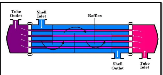
The application of shell and tube exchangers is typically in high pressure processes where the operating pressure sometimes can reach up to 70 bar. Figure 1.1 demonstrates a schematic of shell and tube exchangers and flow stream in both head and shell sides.
In order to have a higher efficiency, there are several parameters which must be considered in the design of shell and tube exchangers:
1) Tube diameter, 2) Tube length, 3) Tube thickness, 4) Tube layout, 5) Tube pitch, 6) Tube corrugation,
7) Baffle design.
Figure 1.1 Shell and tube heat exchanger (http://classes.engineering.wustl.edu/) 1.3 Tube to tubesheet joint
The connection of the tube to the tubesheet should be credited as the most critical element of shell and tube exchangers, due to the fact that its rigidity depends upon many parallel tubes. In fact, the high reliability of this joint can ensure a longer life of the exchanger and minimize the risk of exchanger failure. As a solution, expansion of the tube seems to be a useful technique to reduce the possibility of leakage between two circuits. In this process, the tube is expanded to contact the tubesheet bore and close the gap. A weld around the tube is sometimes added to ensure leak-free tightness. By creating this barrier between the tube and tubesheet, the fluid flow in neither direction is allowed.
According to the fundamentals of the expansion process, there are three main affected zones in the tube, as shown in Figure 1.2:
1) Expansion zone, 2) Transition zone, 3) Unexpanded zone.
However, the expansion process enhances the integrity of the tube-to-tubesheet joint. This process can initiate failure of the tube and tubesheet, which sometimes leads to a complete
degradation of the heat exchangers. The presence of high residual stresses developed during expansion can reach critical values when coupled with the stresses created during the operation, which threatens the strength of the connection with the initiation of crack propagation under a corrosive environment. Hence, the latter necessitates an analysis of the fundamentals to clarify the cause of failure.
Figure 1.2 Tube expansion 1.4 Common expansion processes
The purpose of the tube expansion process is to close the gap between tube and tubesheet and to produce the contact pressure at the interface. By doing this, the flow stream from the primary to second circuit and vice versa is blocked. In this process, based on the expansion pressure level, the tubesheet undergoes either elastic or partially plastic deformation. Therefore, the level of the expansion pressure should be monitored to avoid tube over expansion, which could cause a full plastic deformation of the tubesheet, over thinning of the tube or its extrusion along the tubesheet bore.
There are four common expansion processes in the industry: 1) Mechanical rolling,
2) Hydraulic expansion, 3) Hybrid expansion, 4) Explosive expansion.
1.4.1 Mechanical rolling
This process is the oldest and the most used method for the expansion of tubes. The required time for this process makes it a favorite of manufacturers. The tube expander consists of three major parts, shown in Figure 1.3:
Figure 1.3 Mechanical rollers (www.elliott-tool.com)
1) Roller: This part is used to expand the tube’s inside diameter by applying an imposed displacement by the roller to increase the tube diameter and produce expansion. The number of rollers can vary from 3 to 7 rollers placed at an equal distance around the periphery;
2) Frame: This part holds the rollers and keeps them fixed at an equal interval. Any misplaced rollers lead to a dent forming inside the tube;
3) Mandrel: This component guides the rollers and controls the radial displacement. The mandrel, tube and tubesheet bore axis are concentric. The mandrel roller system is designed to obtain a perfectly inner circular surface of the tube. The mandrel acts by an electrical or pneumatic actuator and can reach speeds up to 1100 rpm.
In mechanical rolling, after releasing the rollers, the tubesheet springs back, compressing the tube to produce a residual contact pressure. Likewise, using this expansion process, the strength of the connection is increased significantly while generating high residual stresses
and undesirable local deformations in the tube, resulting in stress corrosion cracking and stress concentrations. In addition, mechanical rolling results in a higher level of strain hardening in the tube material and a reduction in the contact pressure at the interface.
The biggest disadvantage of mechanical rolling rests in the fact that the residual stresses of the tube cannot be estimated, due to the irregularities of the process and the difficulty in controlling deformation making the effective life of tubes impossible to predict.
1.4.2 Hydraulic expansion
The hydraulic expansion process was proposed by Westinghouse in the mid 70’s. As its name suggests, this method applies hydraulic pressure of water or other fluids to expand the tube.
The elements of the hydraulic process shown in Figure 1.4 are as follows: 1) Probe,
2) Pump, 3) Booster,
4) Pressure gauge, 5) Overflow valve, 6) Hydraulic fluid tank, 7) Control valve.
Prior to loading, the secondary section is filled with fluid and the booster is placed in its initial position. Then, the pressure pump increases the pressure to run the expander (primary pressure) and the booster intensifies this pressure to the required pressure for expansion of the tube. During unloading, the overflow valve discharges the fluid to the tank to relieve the pressure. Figure 1.5 shows a detailed view of hydraulic expansion, which achieves a homogeneous expansion pressure over the inner surface of the tube. According to Krips and Podhorsky (1976), the most important advantage of this process would be highlighted in the fact that the expansion pressure can be determined with high accuracy.
Like mechanical rolling, in this process, the tube undergoes plastic deformation prior to contact with the tubesheet. Also, both tube and tubesheet spring back during unloading, so
the gap might not be fully closed along the tubesheet thickness; this can provoke stress corrosion cracking from the shell side, resulting in internal leakage between two circuits.
Figure 1.4 Diagram of the tube expansion installation (Taken from Krips and Podhorsky, 1976)
Figure 1.5 Schematic of hydraulic expansion process (www.sugino.com)
1.4.3 Hybrid expansion
For the first time, hybrid expansion was proposed by Krips and Podhorsky in 1979, three years after the invention of hydraulic expansion. After being acquainted with some
weaknesses in the former method, the hybrid technique was invented to achieve an optimum design.
Hybrid expansion consists of hydraulic and mechanical rolling processes in succession. This method is able to expand the tubes with high strength materials or combined with multiple materials. The process starts with hydraulic expansion to close the clearance between the tube and tubesheet. Then, mechanical rolling is performed to remove the dents and undesired deformations over the inside surface of the tube in order for the joint to reach higher strength. In fact, after releasing the hydraulic pressure, the tube has enough time to return partially to its initial position, and this leads to the relief the residual stresses.
However, while hybrid expansion achieves superior quality in contrast with the two preceding processes applied individually, the required time for preparation and process is much longer. Therefore, the application of such a process is limited to high-sealed services. 1.4.4 Explosive expansion
Tube expansion by explosion was initially invented by Berman Irwin et al. in 1966. In this process, explosive plugs are placed inside the tube, and an explosion takes place to cause the tube expansion (Figure 1.6). The minimum required preparation time makes this process more desirable. However, explosion impact must be predetermined to have the least damage and unwanted deformation in the joint. In fact, in this process, any damage will lead to the tube plugging from both sides.
After detonation, the outer contact edge of the tube and tubesheet will be seal welded to reduce the possibility of leakage from shell side to head side and vice versa. In addition, mechanical rolling can be applied as a supplement to get a perfectly circular inner surface of the tube.
1.5 Hydraulic expansion principles
The hydraulic expansion process can be divided into two main steps: 1) Loading step, in which the expander is applied to expand the tube; 2) Unloading step, in which the expander is released.
Figure 1.6 Plug installation in explosive expansion (www.tei.co.uk)
As is manifested in Figure 1.7, by applying the expander, the tube expands radially in the elastic range until it reaches point B. In step 2, the tube begins to deform plastically in the tube’s inside diameter, deforming plastically until the outer surface of the tube touches the inner surface of the tubesheet in step of 3. This point is shown as point D in the graph. In this work, it is assumed that the tube undergoes full plastic deformation before it comes into contact with the tubesheet. After that, any increase in the expansion pressure would cause elastic deformation at the tubesheet’s inner surface up to point E, producing a contact pressure at the interface.
It is worthy to note that the slope of line 4 represents the combined rigidity of the assembly, including both the tube and the tubesheet. Up to point E, the expansion pressure Pe is lower
than the pressure to cause yield in the tubesheet Pys and the tubesheet never suffers plastic
deformation. Then, in step 7, the tubesheet deforms elasto-plastically starting at the tubesheet’s inner surface. Finally, step 5 is the unloading phase, during which the tube and tubesheet spring back. The greatest slope of line 5 corresponds to the full elastic rigidity contribution of both the tube and tubesheet and pressure resistance by the whole assembly.
Figure 1.7 Hydraulic expansion steps 1.6 Factors influencing the rigidity of tube to tubesheet connection
In order to reach an optimum design of the tube to tubesheet connection, one should consider the following parameters to reduce the risk of leakage:
1) Expansion pressure, 2) Initial clearance,
3) Residual stresses produced by the expansion process, 4) Final contact pressure between tube and tubesheet, 5) Material properties of tube and tubesheet,
6) Friction at the interface,
7) Tube layout and expansion sequence, 8) Operating conditions.
However, the effect of every single factor may vary, depending on the rigidity of the joint. A comprehensive work requires taking into account the entire engaged parameters, and it is the designer’s responsibility to analyze these factors meticulously as much as possible.
According to the author, the factors mentioned above would be classified into three main sections:
1) Connection geometry, which includes initial clearance, tube and tubesheet inner and outer diameters and their thicknesses, etc.;
2) Mechanical properties of the tube and tubesheet. In this section, elastic modulus, yield stress, plasticity constants, etc. can be considered influence factors;
3) Service conditions, which consider the effect of operational parameters on the performance of shell and tube heat exchangers. These effects are described as below:
a. Thermal stresses produced by temperature gradients between two circuits, b. Differential pressure between two circuits,
c. Equipment vibration due to the misalignment or hydraulic shock, d. Stress corrosion cracking,
e. Fatigue.
1.6.1 Expansion pressure
In the hydraulic expansion method, two O-rings are within a specific distance. This distance is usually the same length as the tubesheet thickness. Therefore, the area between these O-rings will expand. As is mentioned in the foregoing, the accurate determination of the expansion pressure in the hydraulic process can be considered an advantage of this technique. The level of expansion pressure dictates the deformation in the tubesheet. Since such pressure is limited to the one that produces yield stress in tubesheet Psy, the tubesheet just
bears the load to remain in the elastic range and, undoubtedly, any increase in expansion pressure above Psy would result in partial or full plastic deformation of the tubesheet.
There are two limits to define the expansion pressure according to Updike (1989); the lower limit, in which the expansion pressure allows the tube to close the gap with no contact pressure at the interface of tube and the tubesheet, and the upper limit, which is known as the pressure that causes plastic axial extrusion of the tube through the tubesheet bore.
Through the years, several methods were proposed in order to determine the optimum degree of expansion and the “percentage of tube wall thickness reduction” showed the highest reliability and effectiveness. In fact, this method measures the tube wall thinning at the end
of the process. According to Yokel (1992), if the wall reduction reaches 12%, the joint should be rejected.
In addition, over expansion might lead to either higher residual stresses in the assembly or higher strain hardening in both parts, and it reduces the integrity of the joint notably.
1.6.2 Initial clearance
Initial clearance must give enough room to the tube to go under plastic deformation before it comes into contact with the tubesheet. Otherwise, the tube springs back and won’t allow the generation of the interface contact pressure. As a result, fluid can pass through the gap from one side to the opposite side.
The standard of the Tubular Exchanger Manufacturers Association (TEMA) addresses the permissible tubesheet bore diameters and tolerances for each nominal tube OD in Table RCB 7.41. These dimensions prevent the risk of tube thinning, which takes place in the tube wall as a result of over expansion.
Several studies to determine the effect of initial clearance on the rigidity of the tube to tubesheet connection have been undertaken by researchers through the years. Allam et al. (1998) and Merah et al. (2003) performed Finite Element Analyses, and they concluded that for low strain hardening, the effect of initial clearance is negligible. However, with strain hardened materials, the residual contact pressure has been found to decrease linearly when increasing initial clearance [Merah et al., 2003].
1.6.3 Residual stresses produced by the expansion process
Residual stresses are the stresses that remain in the joint at the end of expansion process. However, both the tube and tubesheet should bear a lower level of residual stresses in the hydraulic process. The effect of high residual stresses is considered in this analysis due to its destructive outcome.
Tensile residual stresses are found at the inner and outer surface of expanded tubes and, in the case of micro-crack existence, they accelerate their propagation, which can be accelerated by the presence of corrosion. It is worthy to note that in mechanical rolling, tensile residual stresses on the inner surface of the tube in the transition zone can reach yield stress (Updike
and Kalnins, 1988). Therefore, this zone requires special attention due to the high risk of stress corrosion cracking, since the joint is very often exposed to corrosive services.
In addition, residual stresses affect the mechanical properties of the materials. In fact, these stresses weaken the rigidity of the joint by reducing the yield strength of the material and induce lower corrosion resistance.
In hydraulic expansion, after the loading step, residual stresses reach their peak, but during unloading the tube and tubesheet spring back, which allows the stresses to be relieved and reduced to a certain extent. The advantage of hybrid expansion is to lower strain hardening, which reduces the residual stresses by the quick application of mechanical rolling when the gap is already closed by hydraulic expansion. Therefore, residual stresses are extremely lower in this process.
1.6.4 Contact pressure
The contact pressure produced at the interface of the tube and tubesheet is optimum when the tubesheet is more rigid than the tube. In fact, this facilitates the tube expansion process and reduces undesirable deformation in the tubesheet (Grimison and Lee, 1943).
Two limits are taken into account for contact pressure. The lower limit is represented by cases when the tube’s outer surface touches the tubesheet bore and it leaves no contact pressure at the interface. The upper limit is reached when no tube extrusion occurs along the tubesheet bore. However, the unloading step reduces the residual contact pressure, while the final contact pressure will be generated according to these two limits.
The contact pressure is highly affected by initial clearance and the tube expansion sequences for different tube layouts. In fact, the residual contact pressure is reduced at the interface when adjacent tubes are expanded (Chaaban, 1989). As a result, the number of tubes surrounding a specific tube could have a significant effect on contact pressure (Bouzid, 2016).
1.6.5 Material properties of tube and tubesheet
As it is explained previously, manufacturers of shell and tube exchangers prefer tubesheets with higher strengths than that of the tubes in order to facilitate the expansion process, due to the lower expansion pressure needed to close the gap and produce a rigid connection.
In joint analysis, it is likely to assume for both parts exhibiting isotropic behavior, homogenous materials and free of dislocations and cracks. In addition, the materials do not exhibit strain hardening behavior. The other desired assumption is that the tube undergoes plastic deformation prior to contact with the tubesheet.
The behavior of materials in plastic regime could be another crucial factor in the analysis of tube to tubesheet. Actually, all research conducted on this subject is assumed to obey one of the following plastic behaviors:
1) Elastic Perfectly Plastic (EPP): In fact, EPP is a simplification by considering the tangent modulus equal to zero;
2) Multi-Linear Kinematic Hardening.
The level of the expansion pressure dictates tubesheet behavior. When the maximum expansion pressure Pem is lower than the tubesheet yield pressure Pys, the tubesheet is in the
elastic range. However, any increase in expansion pressure beyond Pys results in plastic
deformation of the tubesheet starting at the inner bore surface. 1.6.6 Friction at the interface
The highest integrity of the joint is obtained once the tube extrusion is prevented through the tubesheet bore (Grimison and Lee, 1943). This could be acquired by higher friction at the interface, although greater friction could cause higher strain hardening in tube material, which can reduce the residual interfacial contact pressure. Therefore, friction has a key role in obtaining a rigid joint.
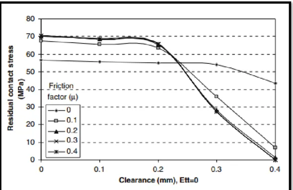
According to Al-Aboodi et al. (2010), a friction coefficient greater than 0.2 has an insignificant effect on the residual contact stress for metal to metal contact, and this value should be considered a turning point. This point is demonstrated in Figure 1.8. Furthermore,
the author investigated the effect of friction on strain hardening and its relation to higher residual stresses at the interface.
Figure 1.8 Influence of friction and radial clearance on interfacial contact stress (Taken from Al-Aboodi et al. 2010)
1.6.7 Tube layout and expansion sequence
The arrangement of tubes and their order of expansion is another dominant factor which should be considered in joint analysis. The most practiced arrangement is surrounding every single tube with at least six adjacent tubes, to place as many tubes as possible in order to increase the heat transfer between the two circuits. The two popular patterns, the square and triangular layouts of tubes, used by the industry are shown in Figure 1.9.
The research devoted to this factor revealed a reduction in the contact pressure of a tube when adjacent tubes are expanded. Therefore, the expansion of tubes needs a particular attention to account for this effect.
In 1993, Huang et al. did a finite element analysis to compare square and triangular arrangements of tubes. He concluded that the average residual contact pressure in the central tube in a triangular layout was 100% greater than that of the square pattern. In fact, the
triangular pattern, due to the number of tubes which surround the central tube, would result in higher rigidity of the joint.
The triangular pattern, in comparison with the square pattern, affords a higher level of heat transfer; however, due to the number of tubes placed in the triangular model, the access to the tube bundle on the shell side is limited and operation requirements for dirty services should be forecasted.
Figure 1.9 Tube square and triangular layouts (http://chemical-eng-world.blogspot.ca) 1.6.8 Operating conditions
Heat exchangers are usually used in elevated temperature services, and this can cause thermal loading in both the tube and the tubesheet and weaken the connection tightness. The generated circumferential thermal gradient can be important depending on the number of passes. In this case, high temperature fluid enters the top section of the head side and leaves at the bottom section of the head side with a much lower temperature. As a result, the
temperature distribution in the tubesheet (Figure. 1.10) leads to thermal loading, which results in either an undesirable distortion of parts or joint loosening.
1.7 Failure mechanisms in tube to tubesheet connection
Recall from the preceding sections that the tube to tubesheet connection plays a significant role in the integrity of heat exchangers. Rigid joints are preferred because they prevent leakage from primary to secondary circuits.
Any failure in a joint may result in total plant shutdown and expensive maintenance. Therefore, periodic inspections of tube to tubesheet connections should be performed in order to detect early stage failure and conduct tube plugging or replacement.
Figure 1.10 Tubesheet different thermal zones (www.china-ogpe.com)
This connection experiences several types of failure mechanisms, which are seen in Figure 1.11 and can be described as following:
1) High residual stresses, 2) Intergranular attack (IGA), 3) Stress Corrosion Cracking (SCC), 4) Fatigue.
1.7.1 Residual stresses Refer to 1.6.3.
Figure 1.11 Example of degradation mechanisms of tube (www.cpuc.ca.gov)
1.7.2 Intergranular attack (IGA)
As the name of this mechanism suggests, this phenomenon takes place along the grain boundaries in the presence of tensile residual stresses, as is demonstrated in Figure 1.12. The main cause of this phenomenon is heterogeneity in local composition (impurities or precipitation), which usually appears during the heating or cooling of the process in the presence of chromium carbides and sulfur formation at the grain boundaries in Alloy 600
tubes of steam generators (Do Haeng Hur et al. 2008). Sulfur reduces the corrosion resistance of the tube material; however, the grain bulk remains initially unaffected.
Figure 1.12 Intergranular attack at tube ID (Photo 2MA0270, Mag: 500X, unetched)
(met-tech.com)
As a result, an intergranular attack seriously affects the mechanical properties of the material by means of full deterioration of grain boundaries. To prevent the intergranular attack, heat treatment and modifications in either the operation or manufacturing processes are proposed by Green S.J. (1986), which can be summarized as follows:
1) Heat treatment at 740°C for 15 hours for Alloy 600 to reduce the residual stresses and to minimize the intergranular attack,
2) Decrease in service temperature and removal of debris and corrosives by tube purge out or water jet washing,
3) Reduce the crevice depth exposed to the secondary circuit on the shell side by the expansion process and dispose of chemical residues, which can be concentrated at this area.
1.7.3 Stress corrosion cracking (SCC)
Stress corrosion cracking is typically produced by corrosion and the influence of tensile stresses, which can be in the form of applied or residual stresses. However, these stresses are usually much lower than the yield stress of the material. Welding, heat treatments and cold forming are examples of residual stresses built up in the material.
In addition to the intergranular paths, the cracks in SCC might progress in transgranular paths. Material, subjected loading and the type of corrosion environment would determine the crack propagation. Figure 1.11 shows several local SCC in a steam generator.
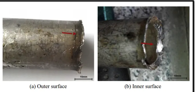
Figure 1.13 Cracks in tube in the immediate vicinity of transition zone (Taken from Shugen Xu et al., 2015)
The crack in the tube-to-tubesheet joint could initiate at the inner or outer surface of the tube, and/ or even at the tubesheet inner bore from the shell side. These cracks are shown in Figure 1.13. As this figure demonstrates, the most susceptible area for crack initiation is the transition zone, where the tensile stresses are concentrated. The transition zone is subjected to the corrosive service of the shell side, which accelerates SCC.
In order to specify the crack type and improve the SCC behavior, metallurgical examinations and corrective interventions should be performed. Such actions must result in a reduction of tensile stresses and corrosion effects. The interventions are described as below:
1) Control the operating temperature;
2) Change the material to avoid chemical reaction to service fluid;
3) Reduce the tensile stresses by means of introducing compressive stresses; 4) Control of service loading.
1.7.4 Fatigue or cyclic stresses
The definition of fatigue by ASTM E1823-97 is: “The process of progressive localized permanent structural change occurring in a material subjected to conditions which produce fluctuating stresses and strains at some points and which may culminate in cracks or complete fracture after a sufficient number of fluctuations.”
In the tube to tubesheet connection, fluctuating stresses may occur due to the mechanical or thermal loading combined with corrosion. Piping vibration and cyclic temperature are two examples of cyclic loading in heat exchangers.
Mechanical fatigue in exchangers usually takes place in stress concentrated areas, such as: tube to tubesheet assembly, baffle connection or welded joints. In fact, these areas, due to their geometry, introduce the tensile stresses, which raises the possibility of the crack propagation and reduce the effective life of the connection. Thermal loading in addition to cyclical stresses can cause crack initiation and in corrosive services results in the exposure of the tube base metal to cyclical corrosion.
The fatigue failure analysis is composed of the following stages of the so-called crack propagation approach:
1) Crack initiation or low speed crack propagation; 2) Steady-state crack growth;
3) High-speed crack propagation leading to ultimate fracture.
In this approach, the required number of cycles from initial crack length to a critical length will be computed based on Paris-Erdogan’s power law, in order to obtain the safe life of parts in the presence of cracks (Fig. 1.14).
Figure 1.14 Three phases of crack growth, Paris–Erdogan's law (www.researchgate.net)
1.8 Determination of residual stresses in transition zone
Due to the complex deformation of the transition zone after the expansion process, the methods used to determine residual stresses at this zone should be meticulous. Effects of expansion pressure through loading and unloading steps must be analyzed separately to obtain the most accurate results.
In this work, analytical and Finite Element Analysis is performed to calculate the expansion process’s residual stresses in the transition zone. Several formulas for different steps of loading and unloading are proposed and, finally, the results are compared to those obtained from the literature. It is worthy to note that Updike in 1988 and Allam in 1998 have undertaken investigations on the evaluation of the residual stresses at the transition zone. The former used an analytical approach based on the incremental plastic theory and FEM, while the latter’s FEA results to determine these stresses at the maximum expansion pressure level have been employed, and the lack of an analytical model presenting stresses at maximum expansion pressure is felt in their studies.
1.8.1 Analytical approach
In the developed analytical model, three main theories have been applied to analyze the expansion process and residual stresses:
1) Thick cylinders,
2) Rigid-plastic cylindrical shell subjected to axial symmetric loading, 3) Beams on elastic foundation.
The thick cylinders theory is used to determine the residual stresses during the loading step by calling the equilibrium equations. In addition, it is assumed that the materials of the tube and tubesheet obey the Von Mises yield criterion of maximum distortion and the materials follow an elastic perfectly plastic behavior. The equations proposed by Laghzale and Bouzid (2009) are taken into account to determine radial displacement of the tube and tubesheet and residual contact pressure at the interface of the expanded zone. Since the tube begins deforming plastically at the junction between the expanded and transition zones, the equations of cylinders under symmetrically axial loading proposed by Sawczuk (1960) are applied to the transition zone.
Two cases, one considering the effect of reverse yielding in the expanded zone on residual stresses during the unloading, are investigated. In the first case, it is assumed that the tube expanded zone and the tubesheet suffer no reverse yielding and their spring back is purely elastic. In this case, the beam of elastic foundation theory is applied to determine the residual stresses during the unloading and, finally, to determine the ultimate residual stresses in the transition zone. In the second case, the expanded zone experiences reverse yielding during unloading, and its effect on residual stresses is studied. It is assumed that the transition zone is not subjected to reverse yielding.
1.8.2 Finite element analysis
To validate the analytical model, Finite Element Analysis using ANSYS Workbench 16.2 is used. A 3-D portion of the tube-to-tubesheet connection is modeled using geometry tools (Figure 1.15) and the static structural analysis module is used to simulate the hydraulic expansion process, including the loading and unloading steps.
In the numerical model, it is assumed that the material follows an elastic perfectly plastic behavior obtained by considering a bilinear isotropic hardening option with a small value of the tangent modulus of less than 0.01 GPa.
It is worthwhile to note that the expansion pressure is restricted to produce elastic deformation in the tubesheet. In addition, the initial clearance is large enough for the tube to go to plasticity prior to contact with the tubesheet.
CHAPTER 2
LITERATURE REVIEW
2.1 Introduction
Oppenheimer (1921) could be named as the first researcher who brought a published scientific contribution to the tube-to-tubesheet connection. Tube expansion has been employed since the 1840s. It wasn’t until 1921 that some experiments devoted to the subject and applied by manufacturers resulted in obtaining acceptable connection rigidity. Therefore, the lack of scientific knowledge was extremely felt then. At the time, the sole process used was mechanical rolling. In 1921, Oppenheimer focused on this method by considering the required electrical power for the different steps of expansion and the effect of holding force on the ultimate rigidity of the joint.
Several research concentrating on the tube to tubesheet connection has been conducted by others since then. In fact, optimization of geometry, expansion pressure and combination of tube and tubesheet materials were the main objectives of these investigations at the time, with no attention to the operating conditions. The operation conditions, for the first time, were considered by the Japanese researcher, Toba (1966). The author undertook an experimental study on the residual stresses and stress corrosion cracking in the vicinity of the expanded joint of aluminum brass tube condensers. The study disclosed the crucial role of residual stresses in connection analysis, which can simply accelerate joint failure.
The weaknesses of the mechanical rolling process and several failures of heat exchangers have compelled researchers to focus more meticulously on the fundamentals of this process and their effects on joint tightness. As a result, Krips and Podhorsky (1976) ended studying the alternative proposed method of tube expansion, which was called hydraulic expansion, both analytically and experimentally. According to the author, the advantage of such a process rests in the accurate determination of the expansion pressure, which is achieved by the hydraulic pressure of water or other fluids.
In 1978, Wilson conducted the first finite element analysis (FEA) of a hydraulically expanded tube to tubesheet connection. In fact, FEA is a cost- and time-effective method used to evaluate the joint parameters as compared to the experimental approach.
In this chapter, an attempt is made to rigorously review the various literature written about tube-to-tubesheet joint expansion by dividing it into experimental, analytical and finite element approaches. The dominant findings of each approach will be discussed in detail in its own section.
2.2 Experimental approach
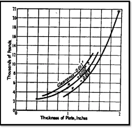
As was mentioned previously, Oppenheimer (1927) carried out the first study on the rolling of tubes into boiler plates to determine the final contact pressure at the interface after unloading. The author concluded that the holding force of shrinking is directly related to the following parameters:
1) The friction coefficient between the tube and tubesheet, 2) The thickness of the tubesheet (Figure 2.1),
3) The amount that the tubesheet bore springs back after withdrawing the expansion pressure, diminished by the amount that the tube springs back, which in turn is directly proportional to the clearance,
4) The ratio of the tube’s outer radius to its wall thickness after rolling, 5) The ratio of pitch to diameter of holes after rolling,
6) Tube and tubesheet materials.
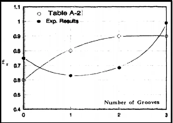
Furthermore, a couple of tests have been elaborated by placing one or several circular grooves in the surface of the tubesheet bore and forcing the tube material to thrust into these grooves. As a result, an increase of 12 times in pure contact pressure since the groove was fully filled with tube material has been observed. Nevertheless, this process requires higher rolling power and grows the strain hardening in comparison with plain rolling.
In 1935, Cassidy (1935) conducted research to investigate the effect of grooves rolling in the plate hole. The results disclosed an increase of 39% and 53% in the contact pressure of one and two grooves respectively, in contrast with the plain drilled bore.
Figure 2.1 Holding force due to shrink fit alone in relation to plate thickness
(Taken from Oppenheimer P.H. 1927)
In 1943, Grimison and Lee undertook an experimental investigation for the Babcock & Wilcox Company to determine the fundamentals of tube expansion, the optimum degree of expansion and various methods of measuring the degree of expansion. The authors concluded that, indeed, the slipping of the tube beyond the limit of expansion reduces the resistance to the extrusion and, to achieve the highest contact pressure, prevention of the tube from extrusion seems to be necessary. In addition, the results showed that the seat pressure increases with tube thickness and hardness of either the tube or tubesheet. According to the author’s observations, in hard plates, pre-rolling gives the maximum seat pressure, with a smaller increase in tube inside diameter. Consequently, less cold working and tube wall thinning are required.
In the same year, Fisher and Cope (1943) proposed a new technique of tube rolling in which small tubes could be expanded automatically to produce a uniform and stable connection. By employing this method, the need for highly skilled and pre-trained operators would be diminished without sacrificing joint quality.
Again, in 1943, Maxwell suggested some modifications in tube expansion using mechanical rollers for the sake of process optimization and a tighter connection. The author recommends using tapered rolls in parallel expansion, which leads to different speeds from end to end of rolls, where it is greater at the large end than the small one. Also, he suggests that the slipping of the roll through the tube’s inner surface begins at a pressure beyond the tube yield point; therefore, the friction should be reduced in order to avoid early local yield starting in the tube material and the build-up of surface irregularity in either the tube or the roll. According to the author, this process could be accomplished either by removing the irregularities and mill scales from the interface or supplying a lubricant which facilitates the roll slipping along the tube’s inner surface.
Furthermore, according to the author, since in heavy tubes, differential temperature occurs during the rolling expansion, which reduces the contact pressure considerably after loading, the multi-stage method could be considered a remedy.
In 1954, Fisher and Brown conducted a comprehensive review of the tube to tubesheet connection by employing years of experience. Their study covers the majority of parameters associated with tube expansion. Some of the dominant conclusions can be summarized as follows:
1) Parallel axis rollers provide a more rigid connection than tapered rollers due to the uniform loading on the tube and tubesheet. Nevertheless, the elastic limit of the joint should be considered a turning point in order to obtain a tight connection;
2) In tube rolling, rollers with sharp ends should be replaced by rollers having a radius of 5 in. in order to avoid scratching the tube’s inner surface;
3) The higher rigidity is achieved since the tube hardness is slightly less than that of the tubesheet material. In this case, a rougher finish has been proposed by authors to increase the sliding resistance of the tube at a higher pressure;
4) Rectangular grooves machined at the tubesheet bore increase the rigidity of the joint by 100% and act as reinforcement. Placing these grooves near the center reduces the potential of shearing the tube metal extruded into the grooves;
5) The clearance should be held as small as possible between 0.005 and 0.008 in. for small seamless drawn tubes. However, for large size tubes, the gap can reach 0.01 in.
In 1956, Alexander and Ford (1956) constructed an apparatus that allows the measurement of strain radially and circumferentially at selected points at the back and front of the tubesheet. The location of these strain gauges is shown in Figure 2.2.
Figure 2.2 Specimen 5 (back) after expanding (Taken from J. M. Alexander, 1956)
The detailed observation of the authors and their conclusions can be explained briefly as follows:
1) The plastic zone in the tubesheet would not pass a ratio of 2.5, which is defined by the plastic radius of the plate to the initial tube radius.
2) The elastic body of the tube at the transition zone constrains the axial extrusion of the tube at the back of the plate. As a result, the strains at the back of the plate are greater than that of the front.
3) The push-out or pull-out load is dependent upon the contact pressure and surface finish of the joint components.