HAL Id: hal-01625032
https://hal.archives-ouvertes.fr/hal-01625032
Submitted on 6 Mar 2019HAL is a multi-disciplinary open access archive for the deposit and dissemination of sci-entific research documents, whether they are pub-lished or not. The documents may come from teaching and research institutions in France or abroad, or from public or private research centers.
L’archive ouverte pluridisciplinaire HAL, est destinée au dépôt et à la diffusion de documents scientifiques de niveau recherche, publiés ou non, émanant des établissements d’enseignement et de recherche français ou étrangers, des laboratoires publics ou privés.
Thermal modeling in composite transmission laser
welding process: light scattering and absorption
phenomena coupling
Andre Chateau Akue Asseko, Benoît Cosson, Fabrice Schmidt, Rémi Gilblas,
Yannick Le Maoult, Eric Lafranche
To cite this version:
Andre Chateau Akue Asseko, Benoît Cosson, Fabrice Schmidt, Rémi Gilblas, Yannick Le Maoult, et al.. Thermal modeling in composite transmission laser welding process: light scattering and absorp-tion phenomena coupling. ESAFORM 2014 - 17th Conference of the European Scientific Associa-tion on Material forming, 2014, Espoo, Finland. p.1560-1567, �10.4028/www.scientific.net/KEM.611-612.1560�. �hal-01625032�
Thermal modeling in composite transmission laser welding process: light scattering and absorption phenomena coupling
André chateau Akué Asséko1,2,a, Benoît Cosson1, Fabrice Schmidt2, Rémi Gilblas2, Yannick Le Maoult2, Eric Lafranche1
1
Mines Douai, MPE-TPCIM, F-59508 Douai, France
2
Université de Toulouse ; Mines Albi, ICA (Institut Clément Ader) ; Campus Jarlard, F-81013 Albi cedex 09, France
a
[email protected], [email protected], c
[email protected], [email protected], [email protected], f [email protected]
Keywords: Laser welding, light scattering, absorption, thermal modeling, thermal
simulations, thermoplastics composites, continuous fiber composite.
Abstract
In previous studies [1, 2], we have presented a detailed formulation of a macroscopic analytical model of the optical propagation of laser beams in the case of unidirectional thermoplastic composites materials. This analytical model presented a first step which concerns the estimation of the laser beam intensity at the welding interface. It describes the laser light path in scattering semi-transparent composites (first component) by introducing light scattering ratio (D) and scattering standard deviation (σ). The absorption was assumed to be negligible in regard to the scattering effect. In this current paper, in order to describe completely the laser welding process in composite materials, we introduce the absorption phenomenon in the model, in the absorbing material (second component), in order to determine the radiative heat source generated at the welding interface. Finally, we will be able to perform a three dimensional temperature field calculation using commercial FEM software. In laser welding process, the temperature distribution inside the irradiated materials is essential in order to optimize the process. Experimental measurements will be performed in order to confirm the analytical model.
Introduction
The literature contains many researches on the modeling of laser welding process for calculating the temperature field in knowing the radiative energy interface (radiative source term) received at the interface. The phenomenon of absorption for semi-transparent materials (absorbent) is modeled using the Beer-Lambert law assuming cold and non-scattering media. The author [3] assumed a density of heat flux with Gaussian distribution to estimate the radiative energy at the interface and calculate the temperature field. In their contribution [4] also considered the same assumptions. The authors in [5] use a simplified model for the diffused intensity into the material using the Beer-Lambert law with the laser beam. Most of the researchers as [6], [7] and [8] consider that the laser beam is absorbed at the interface (opaque medium) and in the second material (absorbent) is transmitted according to the Beer-Lambert. The author in [9] and [10] proposed analytical general solutions (transient and steady state) to estimate the increase of the temperature field at any point of the weld interface. They performed that for fixed and mobile sources of heat considering several forms of surface source (elliptical, circular, rectangular or square).
Aims of the present work are the prediction of the heat source in the laser welding process thermal simulations, in composite materials and at the welding interface. This paper proposes to describe completely the laser welding process in composite materials (refraction and absorption coupling).
Laser welding process
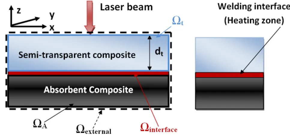
Transmission Laser Welding technique [11] presents specific advantages for industrial applications over other conventional technologies: the method is accurate, flexible, small heat affected zone, easy to automate and control and non-contaminant, heat transfer with the ability to optimize the welding temperature (at the interface of the welding zone), absence of vibration during the welding process (contrary to the ultrasonic welding, friction welding), fast welding speed for welding plastic parts with an acceptable welding time. Transmission Laser Welding of composites involves two joining parts: one semi-transparent to the laser wavelength and the other part is absorbent in the same wavelength. The two parts are positioned together before the welding. The laser beam energy is transmitted through the semi-transparent material and is absorbed within the surface of the second materials (Fig.1). The bonding between the two parts allows the heating of the semi-transparent part by thermal conduction. Thus, melting and fusion of the both materials interface occurs (the bonding between the two parts occurs when T>Tmelt in this area). The energy is deposited at the interface in a localized volume causing the formation of a weld zone. Comparing with welding traditional techniques, laser welding efficiency strongly depends on the optical properties of the material [12]: absorption, transmission, refraction, reflection, scattering and thermal properties: heat capacity, thermal conductivity and density.
Figure 1: Laser welding system [11]
Scattering and absorption phenomena coupling
The laser welding process requires the presence of two phenomena: refraction (causing optical scattering macroscopically semi-transparent in the composite) and the absorption that occurs in the absorbent composite. In order to model the optical behavior of thermoplastic composites, the coupling of these two phenomena must be undertaken. Unlike to thermoplastic welding, the two phenomena cannot be neglected. The absorption is taken into account in the analytical model in order to determine the heat generated in the welding interface and finally to perform a three-dimensional calculation of the temperature field. The absorption in the second part leads to the exponentially decreasing attenuation along the propagation path of the incident laser beam [13]. To determine the generated heat source at
the welding interface, the profile of the distribution of the total transmitted power of the laser beam (the total power after penetrating into the semi-transparent composite and reaching at the welding interface) is used [2]. For a gaussian laser beam, the distribution of the total power of the laser inward beam in the UD semi-transparent composite is:
I x, y, z I e
2πσ σ z σ e for all x $ Ω& (1)
Where x ,y and z are the space variables, σo is the spatial shape parameter of the initial laser
beam (proportional to the beam diameter), σx (scattering standard deviation) is a function of
the thickness , refraction index of matrix and fiber volume fraction and microstructural arrangement and D is the optical scattering coefficient of the semi-transparent composite. In the absorbent part, a high absorption of laser beam radiation is considered, according to Beer-Lambert's law, and a heat transfer by thermal conduction between the two parts. The heat source in the case of an assumed semi-transparent and absorbent composites coupling (Figure 2) is described by the following equation as in [9, 14, 15, 16]:
Figure 2: Semi-transparent and absorbent composites coupling
Q x, y, z (I x, y, z0 semi - transparent part for all x $ ΩK &
2e 34 5 absorbing part for all x $ Ω89 (2)
zs is the distance from the surface with in the material. In our study, recall that the absorption
in the strongly, scattering transparent composite is neglected i.e. assuming ideal semi-transparent material and we consider just a strong absorption at the surface of the absorbent composite (welding interface). The absorption coefficient Ka is considered infinite. That is to
model the heat source in surface flux (surface absorption).
Q x, y, z 1 - ρ& α2I x, y, z for all x $ Ω8 (3)
With α2 1 - ρ2 (absorption factor of the absorbent composite), ρ& reflection coefficient of the transparent composite. Thus, for the Gaussian shape, eq.3 can finally be expressed as follows:
Q x, y, z 1 - ρ& α2 I e
=>
2πσ? σ z σ? e
Where Io is the laser power (W). Preliminary thermal simulation
Knowing the generated heat source, the calculation of the temperature field at the welding interface and in the materials is performed numerically using a finite element model using the heat equation below [3, 4, 5, 6], by taking a perfect contact between the two components subjected to welding. There are also studies that consider a thermal contact resistance between the joining components [8] based on the roughness of the surface and the contact pressure. In the present study, a perfect contact assumption between the two components was considered due to a reduce thickness of the sample (2mm) and the good quality of the contact surface.
@ABDBC @EBFBC @GBHBC I D, F, H JKLM C BCBN for all x $ Ω8 (5)
Where ki is the thermal conductivity in xi direction, JK the density, and cp(T) the specific heat.
For the heat transfer between the two components and the surrounding medium, the boundary condition can be expressed as in [16, 17]:
-@OPPQC. nPQ ST CU- C? εVW CXY- C?Y for all x $ ΩZ &Z[\2]
(6) Where nPQ is the outward normal vector of the surface is the convection heat transfer coefficient (W/m2 K), Ts is the surface temperature (403.15 K), T? is the ambient temperature (293.15
K), ε is material emissivity and σb is the black body emission coefficient (5.67×10⁻⁸ W/m²K4). The convective heat transfer coefficient hc (10.81 W/m2K). We calculate this value
as [18] in by relying on correlations of the exchange coefficients for a planar plate cooled on its top face. In order to determine the temperature field during the laser welding process, the thermal properties of the materials to be welded are required as input parameters to model the thermal process properly namely, thermal conductivity, specific heat and density, which are dependent on temperature. Thermal properties of the materials constituting the composite are different, a factor around 4 exists between resin and fibers conductivities for instance. Moreover, the final composite thermal properties also depend on the spatial organization of its constituents, resulting in anisotropic macroscopic effective properties. The thermal conductivity measurement in the composite is highly delicate, because of the anisotropy of the material on one hand and because of the reactivity of the resin on the other part.
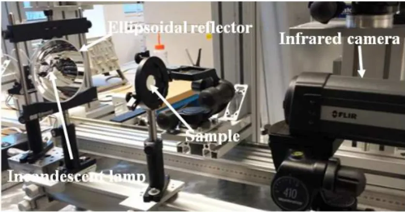
In this study, an experimental method is suggested in order to evaluate global conductivity tensor (kx, ky, kz). A composite sample is submitted on its front face to a heat flux from an
infrared lamp P21W (nominal power: 50W, 13.5V) (Fig.3) focused by an ellipsoidal reflector, thus forming a beam (Gaussian shape). The temperature field on the back face is then measured using a FLIR infrared camera [7-13µm]. From its evolution, we will estimate by inverse method as in [19] using COMSOL software via its optimization tool, the conductivities of the material according to its anisotropy directions. The COMSOL optimization tool is particularly suitable for stationary and transient cases. The optimization solver used is the solver SNOPT [20]. The optimization criterions will use horizontal and/or vertical temperature profiles measured at the back surface of the composite. In our study we use a point (the center of the plaque).
The aim is therefore to minimize the squared difference between the experimental and simulated temperatures profiles. A least squares criterion J is then defined using in that case only the vertical temperature profile by the following relation [21]:
` a b cCZ dZ[efZ\&2] center of plaque - CUefj]2&Z= center of plaque k l
?
(7)
The heat diffusion into the composite thickness is related to its transverse thermal conductivity (kz) and along the perpendicular plane to the thickness of the composite to its
longitudinal thermal conductivities (kx, ky) which also have an influence on the shape of the
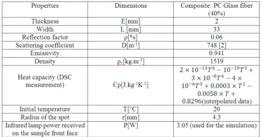
laser beam. In our study, each reinforcement tissue is made of unidirectional glass fibers assembled in a quasi-isotropic draping as in [22]. The thermoplastic composite used in our study is a UD Polycarbonate (PC) Glass fiber reinforced. The initial parameters for the numerical simulation are referenced in the table below:
Table 1: Initial parameters for the numerical simulation
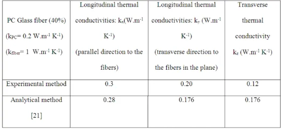
Numerical simulation is compared to experimental data (Fig.4a) versus time. The value of the error at convergence is less than 5% in the center of the plaque. We notice a significant difference between the two curves in the beginning (time < 6 seconds) due to the instability of the numerical model at the beginning of the simulation. Convergence occurs progressively as the time becomes important. As a preliminary validation, we compared our results to the analytical method developed in [21] concerning modeling thermal conductivities in the unidirectional composites. This method used two steps. The first step consists in determining the transverse and longitudinal thermal conductivities of a single unidirectional lamina in
which the fibers are parallel. In the second step, the different orientations of fibers in the stacking sequence are considered to obtain the laminate thermal conductivity tensor. The analytical method is based on an isotropic case due to ahomogeneous fibers distribution in the y and z plane. This leads to ky = kz. However the real microstructure of our composite is a
quasi-unidirectional, which causes a variation of the conductivities in the y and z plane (Tab.2).
Table 2: Simulated thermal conductivities
We performed a simple thermal simulation of the laser welding process with our general analytical model. The laser power used is 30 W. We consider a surface heat source (eq.5) at the interface of two composite parts and we have observed the temperature distribution (Fig.4b) after 5 second of simulation. This will enable us to make later a simplified optimization procedure. We observe a symmetrical distribution of the laser beam (same size and same shape) at the interface (due to surface absorption approach). The temperatures obtained are correct compared to those obtained during the laser welding process, the welding criterion being when T>Tmelt (glass transition temperature for the Polycarbonate [16, 17]).
(a) Experimental and numerical
temperatures on the rear face of the composite versus time (center of
plaque)
(b) Temperature distribution of the
laser beam at the welding interface in the (x , z) plane
Conclusion
The aim of this study was to propose a numerical model in order to predict the heat source in the laser welding process thermal simulations, at the welding interface. This paper presents the complete description of the laser welding process in composite materials (refraction and absorption coupling). In order to determine the temperature field during the laser welding process, the thermal properties of the materials to be welded are required as input parameters to model the thermal transfer. An inverse design method based on experimental measurements performed using infrared camera was used in order to evaluate the global conductivity tensor. We performed subsequently a preliminary thermal simulation (considering a surface heat source) of the laser welding process with our general analytical model. In future prospect, experimental measurements will be performed in order to valid the numerical model.
Acknowledgement: This work could not be possible without the assistance of Jean Michel
MOUYS (ICA-Albi) for helping with the implementation of the experimental set-up.
References
[1] AC. Akué asséko, B. Cosson, F.Schmidt, Y. Le Maoult and E. Lafranche, “Modelling
and simulation of transmission laser welding process of thermoplastics composites,” Esaform 2013.
[2] AC. Akué asséko, B. Cosson, F.Schmidt, Y. Le Maoult and E. Lafranche, “Analytical
and numerical modeling of light scattering in composite transmission laser welding process,”
DOI 10.1007/s12289-013-1154-7. International Journal of Material Forming.
[3] G. N. Labeas, G. A. Moraitis, and C. V. Katsiropoulos, “Optimization of Laser
Transmission Welding Process for Thermoplastic Composite Parts using Thermo-Mechanical Simulation,” Journal of Composite Materials, vol. 44, no. 1, pp. 113–130, Jan. 2010
[4] N. S. Shanmugam, G. Buvanashekaran, K. Sankaranarayanasamy, and S. Ramesh
Kumar, “A transient finite element simulation of the temperature and bead profiles of T-joint laser welds,” Materials & Design, vol. 31, no. 9, pp. 4528–4542, Oct. 2010.
[5] D. A. Grewell and A. Benatar, Plastics and Composites: Welding Handbook. Hanser
Verlag, 2003.
[6] J. M. P. Coelho, M. A. Abreu, and F. Carvalho Rodrigues, “Modelling the spot shape
influence on high-speed transmission lap welding of thermoplastics films,” Optics and Lasers in Engineering, vol. 46, no. 1, pp. 55–61, Jan. 2008.
[7] M. Ilie, J.-C. Kneip, S. Matteï, A. Nichici, C. Roze, and T. Girasole, “Through-transmission laser welding of polymers – temperature field modeling and infrared investigation,” Infrared Physics & Technology, vol. 51, no. 1, pp. 73–79, juillet 2007.
[8] M. Ilie, D. Grevey, S. Mattei, E. Cicala, and V. Stoica, “Diode laser welding of ABS:
[9] Z. B. Hou and R. Komanduri, “General solutions for stationary/moving plane heat source problems in manufacturing and tribology,” International journal of heat and mass transfer, vol. 43, no. 10, pp. 1679–1698, May 2000.
[10] K. J. Suthar, J. Patten, L. Dong, and H. Abdel-Aal, “Estimation of Temperature
Distribution in Silicon During Micro Laser Assisted Machining,” pp. 301–309, Jan. 2008.
[11] M. Troughton, “Chapter 13 - Laser Welding,” in in Handbook of Plastics Joining, Norwich, NY: William Andrew Publishing, 1997, pp. 101–104.
[12] S. W. Churchill, G. C. Clark, and C. M. Sliepcevich, “Light-scattering by very dense
monodispersions of latex particles,” Discuss. Faraday Soc., vol. 30, no. 0, pp. 192–199, Jan. 1960.
[13] M. N. Ozisik. Heat Transfer: A Basic Approach. 1984.
[14] D. Rosenthal. The theory of moving sources of heat and its application to metal treatments. ASME, Cambridge, 1946.
[15] C. MINGLIANG. Gap Bridging in laser transmission welding of thermoplastics. PhD thesis, Queen’s University, Kingston, Ontario, Canada, 2009.
[16] Bappa Acherjee, Arunanshu S.Kuar , Souren Mitra and Dipten Misra, “Effect of
carbon black on temperature field and weld profile during laser transmission welding of polymers: A FEM study,” Optics & Laser Technology., vol. 44, pp. 514–521, 2012.
[17] Bappa Acherjee, Arunanshu S.Kuar , Souren Mitra and Dipten Misra, “Modeling of
laser transmission contour welding process using FEA and DoE,” Optics & Laser Technology., vol. 44, pp. 1281–1289, 2012.
[18] S Andrieu, “Étude expérimentale et numérique du chauffage infrarouge de plaques
thermoplastiques pour le thermoformage,” PhD thesis, Ecole des Mines de Paris, 2005.
[19] J-L. Bailleul, D. Delaunay, Y. Jarny, T. Jurkowski, “Thermal conductivity of
unidirectional reinforced composite material. Experimental measurement as a function of state of cure.,” Journal of Reinforced Plastics and Composites, pp. 52-64, 2001.
[20] Gill P-E, Murray W., Saunders M-A., “User’s guide for SNOPT version 7”, Software for Large-Scale Nonlinear Programming, , 2008.
[21] Maxime Villière, Damien Lecointe, Vincent Sobotka, Nicolas Boyard and Didier
Delaunay, “Experimental determination and modeling of thermal conductivity tensor of carbon/epoxy composite,” Composite part A, vol. 46, pp. 60–68, 2013.
[22] Nakouzi, Sawsane, “Modélisation du procédé de cuisson de composites infusés par
![Figure 1: Laser welding system [11]](https://thumb-eu.123doks.com/thumbv2/123doknet/12503608.340500/3.892.236.547.652.835/figure-laser-welding-system.webp)