Pépite | Contribution à la modélisation par champs de phase des dommages par irradiation dans les alliages métalliques
174
0
0
Texte intégral
(2) Thèse de Gabriel Franck Bouobda Moladje, Université de Lille, 2020. Ph.D. MANUSCRIPT Submitted and defended at UNIVERSITY OF LILLE Ecole Doctorale Sciences de la Matière, du Rayonnement et de l’Environnement Field: Materials sciences by:. Gabriel Franck BOUOBDA MOLADJE. Contribution to phase-field modelling of irradiation damage in metallic alloys. Ph.D to be defended on 27 january 2020 before the Examination Committee:. M. Pascal BELLON University of Illinois Reviewer M. Thomas JOURDAN CEA Reviewer Mme Helena ZAPOLSKY Université de Rouen Examiner, president of the jury M. Pierre-Antoine GESLIN CNRS Examiner M. Ludovic THUINET ENSCL Supervisor Mme Charlotte BECQUART ENSCL Supervisor M. Alexandre LEGRIS Université de Lille Supervisor 2. © 2020 Tous droits réservés.. lilliad.univ-lille.fr.
(3) Thèse de Gabriel Franck Bouobda Moladje, Université de Lille, 2020. 3. © 2020 Tous droits réservés.. lilliad.univ-lille.fr.
(4) Thèse de Gabriel Franck Bouobda Moladje, Université de Lille, 2020. Abstract The prediction of the microstructure evolution during irradiation ageing of structural materials of nuclear reactors is a key issue for the nuclear industry. In this work, a phase field approach is used to simulate the microstructure evolution of materials under irradiation conditions at the mesoscopic scale. We are interested at first in the calculations of the sink strength which describes the ability of microstructural defects (dislocations, cavities, etc) to absorb point defects (PDs). These calculations take into account the elastic interactions between point defects and sinks and are performed in pure metals Al, Ni and Fe. Additional precision in the calculations is provided by incorporating in the model the change of the PD migration energy due to the sink strain field, also known as elastodiffusion. PDs are elastically modelled through their elastic dipole tensors and the role of the anisotropy of these dipole tensors at saddle state is investigated. The results show that the PD dipole tensor anisotropy at saddle state is a key parameter in the accurate sink strength calculations. Subsequently, our interest is focused on the development of a PF model of dislocation climb under irradiation. The model allows to simulate dislocation loop growth or shrinkage by absorption of both PDs (vacancies and self-interstitial atoms). The analysis of the validation tests shows the limit of the model, and adjustments are carried out. This new model is applied to simulate the growth of an interstitial loop in pure Fe. The temperature, dislocation density, loop orientation and elastodifusion effects on the loop growth rate are studied. The results show, in particular, an increase of the loop growth rate with the combined effects of the increase of the temperature and the decrease of the dislocation density. The new PF model of dislocation climb under irradiation is also used to simulate the radiation induced segregation (RIS) phenomenon in Fe-Cr alloy near an interstitial dislocation loop during its growth. We show that the RIS prediction depends on the sink mobility and on the surrounding microstructure (multi-sink effects). Keywords: modelling and simulation, metallic alloys, irradiation, point defects, sink strength, dislocation climb, radiation induced eegregation, phase-field, elastodiffusion. Résumé La prévision de l’évolution de la microstructure au cours du vieillissement par irradiation des matériaux de structure des réacteurs nucléaires est une question clé pour l’industrie du nucléaire. Dans ce travail, une approche par champ de phase est utilisée pour simuler l’évolution de la microstructure de matériaux dans des conditions d’irradiation à l’échelle mésoscopique. Nous nous intéressons tout d’abord aux calculs de la force de puits, c’est-àdire la capacité des défauts de la microstructure (dislocations, cavités, etc) à absorber les défauts ponctuels (DPs). Ces calculs prennent en compte les interactions élastiques entre les défauts ponctuels et les puits et sont réalisés dans les métaux purs d’ Al, Ni et Fe. Une précision supplémentaire dans ces calculs est fournie en incorporant dans le modèle le changement de l’énergie de migration des DPs en raison du champ de déformation dû au puits, encore appelé élastodiffusion. Les DPs sont modélisées élastiquement par leurs tenseurs dipolaires élastiques et le rôle de l’anisotropie de ces tenseurs dipolaires au point de col est étudié. Les résultats montrent que l’anisotropie du tenseur dipolaire au point col 4. © 2020 Tous droits réservés.. lilliad.univ-lille.fr.
(5) Thèse de Gabriel Franck Bouobda Moladje, Université de Lille, 2020. est un paramètre clé dans les calculs précis de la force de puits. Par la suite, notre intérêt est centré sur le développement d’un modèle champ de phase de montée de dislocation sous irradiation. Le modèle permet de simuler la croissance ou le retrait d’une boucle de dislocation par absorption des deux DPs (lacunes et atomes auto-interstitiels). L’analyse des tests de validation montre la limite du modèle et des ajustements sont effectués. Ce nouveau modèle est appliqué pour simuler la croissance d’une boucle interstitielle dans le Fer pur. Les effets de la température, de la densité de dislocations, de l’orientation de la boucle et de l’élastodifusion sur le taux de croissance de la boucle sont étudiés. Les résultats montrent notamment une augmentation du taux de croissance de la boucle avec les effets combinés de l’augmentation de la température et de la diminution de la densité de dislocations. Le nouveau modèle de montée de dislocation sous irradiation développé est également utilisé pour simuler le phénomène de ségrégation induite par irradiation (SII) près d’une boucle de dislocation interstitielle au cours de sa croissance, dans des alliages Fe-Cr. Nous montrons que la prédiction de la SII dépend de la mobilité du puits et de la microstructure environnante (effets multi-puits). Mots clés: modélisation et simulation, alliages métalliques, irradiation, défauts ponctuels, force de puits, montée de dislocation, segregation induite par irradiation, champ de phase, élastodiffusion. 5. © 2020 Tous droits réservés.. lilliad.univ-lille.fr.
(6) Thèse de Gabriel Franck Bouobda Moladje, Université de Lille, 2020. Acknowledgments I would like to thank first all the jury members of my PhD thesis for kindly evaluating my work: Mrs Helena ZAPOLSKY (president of the jury) and Mr. Pierre-Antoine GESLIN as examiners, Mr. Pascal BELLON and Mr. Thomas JOURDAN as reviewers. During these 3 years of thesis, I had a great pleasure working under the supervision of Ludovic, Charlotte and Alexandre. An infinite thank you to you Ludovic for all your precious advices, your patience, your availability, for the rigor in the scientific approach that you have been able to transmit to me with care, it was a great adventure. A very special thank you to you Charlotte for always being there to correct me, for your precious advices, for pushing me to better value my work and to have more confidence in me. Many thanks to you also Alexandre for all the fruitful discussions we had and for all your advice full of wisdom. Thank you for taking me as your PhD student, it was really nice. I also want to say thank you to Pierre, Philippe and Patrick, members of the plasticity team of UMET with whom I did my research internship and had a very nice initiation to the world of modeling. Thank you for everything... During this time spent within the MPGM team of UMET, I met great people: Adithya: thank you bro; Arthur the king ("c’est honteux"): too strong at word games, hahaha ... ; Billy ("bro Camer"); Carmen ("méli-mélo"); Corinne; Damien: thank you for your hospitality and your good mood; Devadas ("nearhhh douchebag"): thank you for all bro, it was very fun (copy+paste, hahaha...); Gulzar; Ingrid ("huummm excellent"); Ines: thank you for these beautiful moments, it was really great your highness, hahaha...; Isadora: I would never walk alone, but never with Liverpool you know why... hahaha, thank you for all and especially for shared football moments; Isabelle; Jean-Bernard: the best practical teacher to prepare a good coffee, hahaha...; Jérôme: the king of LATEX, thank you for all your precious advice; Jérémie; Julie: we really drooled at the end Julie, you are the best never forget; Kaoutar: I know we bothered you a lot with our discussions, thank you very much for your patience and your kindness; Laïs (Gabiiii the bastard): sorry to have bothered you a lot especially at the end of my thesis, spare the rod and spoil the child and so thank you for supporting me; Mahira: the only one I had electric shock with when greeting each other, but it was fun, Marc-Antoine; Marco ("Polo"): thanks for the hot sauce hahaha...; Maxime: thank you for your hospitality and these beautiful moments of futsal; Mourtada, Romain my brother and love for life: it was a great adventure that led to a very nice friendship, we went through good and not so good moments which strengthened our ties, thank you again for being my victim at FIFA, Sabrina the "boss": you are really special and original, thank you for all these wonderful moments, you are the best and never forget that; Thibault: despite the short time spent together we shared wonderful moments (in the circle of doctors, haha), you knew how to revive the group; Yesmine: you are really nice, we also shared some great moments, thanks for everything; Yvan ("bro Camer")... Thank you so much to all my friends: william, Igor, christian, Noëlle, Mirabelle, Franck, Ulrich, Issa ("Makoun"), Caleb, Rodrigue, ... (from Ngoa Ekélé), Cyrille, Natacha, Mimi, Franck (Tappa), Nelson, Gautier, ... (from Emana), Jeanne, Melissa, Vanessa, 6. © 2020 Tous droits réservés.. lilliad.univ-lille.fr.
(7) Thèse de Gabriel Franck Bouobda Moladje, Université de Lille, 2020. Mahel, Achille ("Chelsea"), Tam ("le big"), ... (from Lille), ... ! Thank you so much Mrs Endale for your support and devotion, you really are a gift from heaven... To all my family, thank you so much!. 7. © 2020 Tous droits réservés.. lilliad.univ-lille.fr.
(8) Thèse de Gabriel Franck Bouobda Moladje, Université de Lille, 2020. 8. © 2020 Tous droits réservés.. lilliad.univ-lille.fr.
(9) Thèse de Gabriel Franck Bouobda Moladje, Université de Lille, 2020. Contents. List of acronyms and nomenclature. 14. Introduction. 17. 1 irradiation effects 1.1 Irradiated materials . . . . . . . . . . 1.1.1 Lattice defects . . . . . . . . . 1.1.2 Irradiation effects . . . . . . . . 1.2 Modelling techniques . . . . . . . . . . 1.2.1 Ab initio/DFT . . . . . . . . . 1.2.2 Kinetic monte Carlo . . . . . . 1.2.3 Phase field . . . . . . . . . . . 1.2.4 Mean field rate theory (MFRT) 1.3 Summary . . . . . . . . . . . . . . . .. . . . . . . . . .. . . . . . . . . .. . . . . . . . . .. . . . . . . . . .. . . . . . . . . .. . . . . . . . . .. . . . . . . . . .. 19 20 20 23 24 25 25 26 26 27. 2 Elastodiffusion 2.1 Bibliography . . . . . . . . . . . . . . . . . . . . . . . . . . . . . 2.1.1 Sink strength: definition and calculations . . . . . . . . . 2.1.2 PD diffusion modified by the sink strain field . . . . . . . 2.2 PF methodology . . . . . . . . . . . . . . . . . . . . . . . . . . . 2.2.1 Order parameters . . . . . . . . . . . . . . . . . . . . . . . 2.2.2 Energy of the system . . . . . . . . . . . . . . . . . . . . . 2.2.3 Kinetic equations . . . . . . . . . . . . . . . . . . . . . . . 2.3 Applications to pure Al, Ni (fcc) and Fe (bcc) . . . . . . . . . . . 2.3.1 Sinks description, stress field and sink strength validation 2.3.2 Physical parameters for applications . . . . . . . . . . . . 2.3.3 Results . . . . . . . . . . . . . . . . . . . . . . . . . . . . 2.3.3.1 Straight dislocation . . . . . . . . . . . . . . . . 2.3.3.2 Grain boundary . . . . . . . . . . . . . . . . . . 2.3.3.3 Spherical cavity . . . . . . . . . . . . . . . . . .. . . . . . . . . . . . . . .. . . . . . . . . . . . . . .. . . . . . . . . . . . . . .. . . . . . . . . . . . . . .. . . . . . . . . . . . . . .. . . . . . . . . . . . . . .. 29 30 30 34 36 36 36 39 41 41 49 51 51 62 71. . . . . . . . . .. . . . . . . . . .. . . . . . . . . .. . . . . . . . . .. . . . . . . . . .. . . . . . . . . .. . . . . . . . . .. . . . . . . . . .. . . . . . . . . .. . . . . . . . . .. . . . . . . . . .. . . . . . . . . .. . . . . . . . . .. . . . . . . . . .. 9. © 2020 Tous droits réservés.. lilliad.univ-lille.fr.
(10) Thèse de Gabriel Franck Bouobda Moladje, Université de Lille, 2020. CONTENTS 2.4. Conclusion. CONTENTS . . . . . . . . . . . . . . . . . . . . . . . . . . . . . . . . . . . . 78. 3 Phase field model of dislocation climb generalized to vacancies and SIAs: application to dislocation loop evolution under irradiation 83 3.1 Bibliography . . . . . . . . . . . . . . . . . . . . . . . . . . . . . . . . . . . 85 3.2 PF methodology . . . . . . . . . . . . . . . . . . . . . . . . . . . . . . . . . 88 3.2.1 Order parameters . . . . . . . . . . . . . . . . . . . . . . . . . . . . . 88 3.2.2 Energy of the system . . . . . . . . . . . . . . . . . . . . . . . . . . . 88 3.2.3 Kinetic equations . . . . . . . . . . . . . . . . . . . . . . . . . . . . . 90 3.2.3.1 Determination of the coefficient Ldηl . . . . . . . . . . . . . 91 3.2.3.2 Irradiation conditions . . . . . . . . . . . . . . . . . . . . . 92 3.2.4 Numerical scheme and multi-time step algorithm . . . . . . . . . . . 93 3.2.5 Analytical expressions of the climb velocity . . . . . . . . . . . . . . 94 3.3 Validation and limitations of the model . . . . . . . . . . . . . . . . . . . . 97 3.3.1 Without elastic interactions . . . . . . . . . . . . . . . . . . . . . . . 98 3.3.1.1 Influence of the coefficient ζηd (simulation type 1) . . . . . . 101 3.3.2 With elastic interactions . . . . . . . . . . . . . . . . . . . . . . . . . 104 3.3.2.1 Influence of the coefficient ζηd on the climb rate (simulation type 2) . . . . . . . . . . . . . . . . . . . . . . . . . . . . . 108 3.3.2.2 Influence of the PD relaxation volume Ωd on the climb rate (simulation type 2) . . . . . . . . . . . . . . . . . . . . . . 110 3.4 Application to bcc iron . . . . . . . . . . . . . . . . . . . . . . . . . . . . . . 112 3.4.1 Growth of a <100>-type interstitial loop in a system free of any other sink (simulation type 1) . . . . . . . . . . . . . . . . . . . . . . 112 3.4.2 Growth of an interstitial loop in a system containing a planar sink (simulation type 2) . . . . . . . . . . . . . . . . . . . . . . . . . . . . 115 3.4.2.1 Temperature effect . . . . . . . . . . . . . . . . . . . . . . . 116 3.4.2.2 Loop orientation effect . . . . . . . . . . . . . . . . . . . . 118 3.4.2.3 Elastodiffusion effect . . . . . . . . . . . . . . . . . . . . . . 119 3.4.3 Discussion . . . . . . . . . . . . . . . . . . . . . . . . . . . . . . . . . 120 3.5 Conclusion . . . . . . . . . . . . . . . . . . . . . . . . . . . . . . . . . . . . 121 4 Radiation induced segregation prediction near prismatic interstitial dislocation loops in Fe-Cr alloys 123 4.1 Bibliography . . . . . . . . . . . . . . . . . . . . . . . . . . . . . . . . . . . 124 4.2 PF methodology . . . . . . . . . . . . . . . . . . . . . . . . . . . . . . . . . 126 4.2.1 Order parameters . . . . . . . . . . . . . . . . . . . . . . . . . . . . . 126 4.2.2 Energy of the system . . . . . . . . . . . . . . . . . . . . . . . . . . . 126 4.2.3 Kinetic equations . . . . . . . . . . . . . . . . . . . . . . . . . . . . . 126 4.2.4 Numerical scheme and multi-time step algorithm . . . . . . . . . . . 129 4.3 RIS prediction in Fe-Cr alloys near <100>-type prismatic interstitial dislocation loop . . . . . . . . . . . . . . . . . . . . . . . . . . . . . . . . . . . . 130 4.3.1 RIS prediction under the assumption of static dislocations . . . . . . 131 4.3.2 Effects of the dislocation climb rate on RIS prediction . . . . . . . . 137 10. © 2020 Tous droits réservés.. lilliad.univ-lille.fr.
(11) Thèse de Gabriel Franck Bouobda Moladje, Université de Lille, 2020. CONTENTS. CONTENTS 4.3.2.1. 4.4. Simulation type 1: system containing a dipole of edge dislocations free of any other sink . . . . . . . . . . . . . . . 4.3.2.2 Simulation type 2: system containing a dipole of edge dislocations and a planar sink . . . . . . . . . . . . . . . . . 4.3.3 Simulation type 3: system containing a dipole of edge dislocations with a mean sink strength ks2 associated to the other sinks . . . . . Conclusion . . . . . . . . . . . . . . . . . . . . . . . . . . . . . . . . . . .. Conclusion and perspectives. . 138 . 143 . 148 . 150 153. A Numerical scheme and algorithm to treat the diffusion equation when elastodiffusion is considered 157 B Derivation of the evolution equations. 163. Bibliography. 165. 11. © 2020 Tous droits réservés.. lilliad.univ-lille.fr.
(12) Thèse de Gabriel Franck Bouobda Moladje, Université de Lille, 2020. CONTENTS. CONTENTS. 12. © 2020 Tous droits réservés.. lilliad.univ-lille.fr.
(13) Thèse de Gabriel Franck Bouobda Moladje, Université de Lille, 2020. 13. © 2020 Tous droits réservés.. lilliad.univ-lille.fr.
(14) Thèse de Gabriel Franck Bouobda Moladje, Université de Lille, 2020. List of acronyms and nomenclature. AKMC bcc DFT dpa fcc GGA LDA KMC MC MFRT OKMC PD PKA PF RIP RIS RT RTA SIA STGB TEM T kB V Vat Ωd a0 Edf F Fchem Fel Fcore 2 ks,d Kd0 Bs. © 2020 Tous droits réservés.. Atomistic kinetic Monte Carlo Body centered cubic Density functional theory Displacements per atom Face centered cubic Generalized gradient approximation Local density approximation Kinetic Monte Carlo Monte Carlo Mean field rate theory Object kinetic Monte Carlo Point defect Primary knock-on atom Phase field Radiation induced precipitation Radiation induced segregation Rate theory Residence time algorithm Self-interstitial atom Symmetric tilt grain boundary Transmission electron microscopy Temperature in K Boltzmann constant Volume of the system atomic volume Relaxation volume of PD d PF grid spacing PD formation energy Total free energy of the system Chemical energy of the system Elastic energy of the system Dislocation core energy Sink strength of sink s for PD d Generation rate of PD d 14 Bias of sink s. lilliad.univ-lille.fr.
(15) Thèse de Gabriel Franck Bouobda Moladje, Université de Lille, 2020. ¯d X d Xeq Xds ηs λs vη µchem µel jid abs js,d Ddij Mdij Pdij b q ∇ µ ν Cijkl Sijkl Gij ε0ij εij σij ui δij ic. Average atomic fraction of PD d Thermal equilibrium PD atomic fraction Atomic fraction of PD d at the sink s Elastic field associated to the sink s Shape function of the capture region of sink s Dislocation climb velocity Chemical potential Elastic potential Flux of PD d Rate abosrption of PD d by the sink s PD diffusion tensor Mobility tensor of PD d Elastic dipole tensor of PD d Burgers vector Wave vector Gradient operator Shear modulus Poisson coefficient Elastic constants tensor Eshelby tensor Green function Eigenstrain tensor Total strain in the system Total stress in the system Displacement field Kronecker symbol Imaginary complex number. 15. © 2020 Tous droits réservés.. lilliad.univ-lille.fr.
(16) Thèse de Gabriel Franck Bouobda Moladje, Université de Lille, 2020. 16. © 2020 Tous droits réservés.. lilliad.univ-lille.fr.
(17) Thèse de Gabriel Franck Bouobda Moladje, Université de Lille, 2020. Introduction. Structural materials of nuclear reactors are subject to rough operating conditions such as fast neutron irradiation, high temperatures and mechanical stresses. Thus, their functional properties deteriorate due to irradiation ageing which limits the operating time of components. Therefore, understanding and predicting the evolution of the properties of these structural materials are crucial issues for the safety and security of nuclear reactors. During irradiation ageing, several phenomena are observed such as irradiation creep, swelling, radiation induced segregation (RIS), etc. These phenomena can be explained by the evolution of microstructural defects. For instance, dislocation loop growth allows to explain irradiation creep, cavity growth is responsible for swelling, and the coupling between the fluxes of point defects (PDs) and the ones of atoms allows to explain RIS. The challenge is then to predict the evolution of these microstructural defects. For this purpose, modelling techniques are developed and are good alternatives compared to experiments because of several reasons such as the cost and security. To treat the different physical phenomena occurring at different time scales and length scales such as the PD migration mechanism which occurs at the atomic scale and the dislocation loop growth which can be described at the mesoscopic scale, a multiscale approach is generally used. The present work is dedicated to the simulation of microstructure evolution under irradiation using a phase field (PF) approach. The evolution of microstructural defects depends on their ability to absorb PDs, known as sink strength. The first objective is thus to compute the sink strength by taking into account elastic interactions between PDs and sinks. The influence of the modification of the PD migration rate by an elastic strain field is investigated. Recently, PF models were developed to describe dislocation climb [1, 2, 3]. They are limited to climb via vacancy diffusion and are not adapted to irradiation conditions. The second objective is thus to develop a new PF model of dislocation climb based on the previous ones [1, 2, 3] to simulate dislocation loop evolution (growth/shrinkage) under irradiation. The final objective is to simulate the RIS phenomenon near an interstitial dislocation loop during its growth by means of the new PF model developed. This manuscript is organized as follows: In chapter 1 microstructural defects intrinsic to the materials or formed under irradiation by PD agglomeration are described. Different simulation methods of microstructure evolution are also presented in this chapter. 17. © 2020 Tous droits réservés.. lilliad.univ-lille.fr.
(18) Thèse de Gabriel Franck Bouobda Moladje, Université de Lille, 2020. INTRODUCTION The sink strength is calculated in chapter 2 for straight dislocations, low-angle symmetric tilt grain boundaries and spherical cavities in fcc (Al, Ni) and bcc (Fe) pure metals. These calculations take into account the elastic interactions between PDs and sinks like in the PF model of Rouchette et al. [4]. In addition to this model [4], elastodiffusion effects are incorporated and a particular emphasis is placed on the role of the PD anisotropy at saddle state. In chapter 3, a new PF model of dislocation climb under irradiation is developed. This new model is based on the one developed by Geslin et al. [1] and is adapted to deal with both vacancy and self-interstitial atom (SIA) diffusion. Several tests are performed to validate this new model under irradiation conditions, and some adjustments are proposed to overcome the problems encountered. Thereafter, the model is applied to simulate the growth of an interstitial dislocation loop in pure bcc iron. The temperature, loop orientation and elastodiffusion effects on the loop growth rate are investigated. Finally, the RIS phenomenon near an interstitial dislocation loop is simulated in chapter 4 in Fe-Cr alloys. The elastic effects are taken into account as well as the loop growth rate by means of the climb model developed in chapter 3.. 18. © 2020 Tous droits réservés.. lilliad.univ-lille.fr.
(19) Thèse de Gabriel Franck Bouobda Moladje, Université de Lille, 2020. Chapter 1 Microstructure evolution under irradiation and modelling techniques. Contents 1.1. 1.2. 1.3. Irradiated materials . . . . . . . . . . . . . . . . . . . . . . . . . . 20 1.1.1. Lattice defects . . . . . . . . . . . . . . . . . . . . . . . . . . . .. 20. 1.1.2. Irradiation effects . . . . . . . . . . . . . . . . . . . . . . . . . . .. 23. Modelling techniques . . . . . . . . . . . . . . . . . . . . . . . . . 24 1.2.1 1.2.2. Ab initio/DFT . . . . . . . . . . . . . . . . . . . . . . . . . . . . Kinetic monte Carlo . . . . . . . . . . . . . . . . . . . . . . . . .. 25 25. 1.2.3. Phase field . . . . . . . . . . . . . . . . . . . . . . . . . . . . . .. 26. 1.2.4. Mean field rate theory (MFRT) . . . . . . . . . . . . . . . . . . .. 26. Summary . . . . . . . . . . . . . . . . . . . . . . . . . . . . . . . . 27. 19. © 2020 Tous droits réservés.. lilliad.univ-lille.fr.
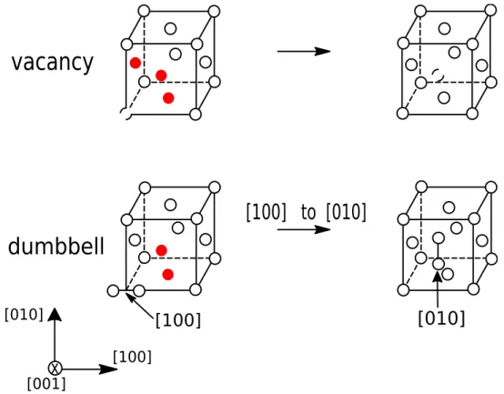
(20) Thèse de Gabriel Franck Bouobda Moladje, Université de Lille, 2020. 1.1. IRRADIATED MATERIALS. CHAPTER 1. IRRADIATION EFFECTS. Under irradiation, microstructural defects such as dislocation loops, grain boundaries and cavities evolve through different mechanisms and this evolution leads to the change in the mechanical properties of nuclear materials. In this chapter, microstructural defects are first described. Secondly, the phenomena which are observed during the microstructure evolution are presented, as well as, the different modelling techniques which allow to predict it.. 1.1. Irradiated materials. Metallic alloys are used for the reactor component structure in the nuclear industry. To ensure the safety and security of the nuclear reactors, these structural materials are chosen according to several criteria such as stability under irradiation, corrosion and swelling resistance, manufacturing cost, etc. For example, zirconium alloys and austenitic steels are used respectively for the fuel cladding structure and the internal reactor vessel structure in pressurized water reactor. Ferritic/martensitic steels and nickel based alloys are candidate materials for innovative reactor systems [5]. The prediction of the evolution of these structural materials is then a key issue for the nuclear industry. The evolution of microstructure is controlled by the evolution of its defects which can be intrinsic (lattice defects) or formed under irradiation. These different microstructural defects are described below.. 1.1.1. Lattice defects. All real materials contain imperfections that can be point, line, surface or volume defects. In this thesis, the discussions will mainly focus on point defects (PDs) and dislocations (line defects). Point defects Two PDs are intrinsic to the material: vacancy and self-interstitial atom (SIA). Vacancy is an atom missing from a lattice site which is normally occupied in a perfect lattice. SIA is an atom that occupies a place outside the normal lattice position. In this thesis, typical fcc (Al and Ni pure metals) and bcc (Fe pure metal and Fe-Cr alloys) structure materials will be particularly studied. The possible configurations of SIA in these structures are the following: octahedral, tetragonal, dumbbell where two atoms share a single lattice site, and crowdion where N+1 atoms share N single lattice sites which leads to the extended distortion of the crystal lattice in the <111> direction (first noted by Paneth [6]). The most stable SIA configuration in fcc structure is generally the <100>-dumbbell [7] and in bcc structure the <111>-dumbbell, but in bcc iron it is the <110>-dumbbell which is more stable due to magnetism [8]. The PD diffusion in a crystal lattice occurs by a displacement from an equilibrium configuration to a nearest neighbor one. During this transition, the energy landscape presents a maximum and the PD configuration which corresponds to this maximum is the called saddle state. The required energy for this transition is the migration energy Em and it is the difference between the energy at the 20. © 2020 Tous droits réservés.. lilliad.univ-lille.fr.
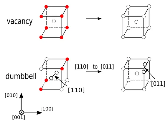
(21) Thèse de Gabriel Franck Bouobda Moladje, Université de Lille, 2020. CHAPTER 1. IRRADIATION EFFECTS. 1.1. IRRADIATED MATERIALS. saddle Esad and stable Ee states: Em = Esad − Ee. (1.1). Vacancy migrates through the motion of an atom located initially on the final stable configuration of vacancy. The 12 (respectively 8) possible jumps in fcc (respectively bcc) structure are then accessible. The dumbbell migration mechanism is more complex than the one of vacancy. The most favorable one is a mechanism of translation-rotation from an initial orientation to a different one, for the metals specified above. Therefore, for a given initial dumbbell orientation in fcc (respectively bcc) structure, 8 (respectively 4) possible jumps are energetically accessible. The possible PD transitions in fcc (Al, Ni) and bcc (Fe) structures are depicted in Figs. 1.1 and 1.2, and all the corresponding jump directions are given in table 1.1.. vacancy. [100] to [010]. dumbbell [010]. [010]. [100]. x. [100]. [001] Figure 1.1: Possible PD transitions in pure fcc metals. The allowed target sites are marked in red.. Dislocations Dislocations are linear defects which exist in materials and allow understanding plastic deformation. A dislocation is characterised by its vector line l and Burgers vector b (deformation amplitude transported by the dislocation) and there are two basic types of dislocation: edge dislocation and screw dislocation as illustrated on Fig. 1.3. In general dislocation has a mixed character. Only edge dislocations will be addressed in this 21. © 2020 Tous droits réservés.. lilliad.univ-lille.fr.
(22) Thèse de Gabriel Franck Bouobda Moladje, Université de Lille, 2020. 1.1. IRRADIATED MATERIALS. CHAPTER 1. IRRADIATION EFFECTS. vacancy. [110] to [011]. dumbbell. [011]. [110]. [010]. x. [100]. [001] Figure 1.2: Possible PD transitions in pure bcc metal Fe. The allowed target sites are marked in red. Table 1.1: Possible jump directions of PD in R0 ([100],[010],[001]) space. Jump direction h. Vacancy. Dumbbell [100] in Al, Ni and [110] in Fe. Al and Ni (fcc). Fe (bcc). [¯110], [1¯10], [0¯11], [011¯], [¯101], [10¯1],. [¯1¯10] [0¯1¯1] [¯10¯1]. [111], [¯111], [1¯11], [11¯1] [¯1¯11], [11¯¯1], [¯11¯1], [¯1¯11¯]. [110], [¯110], [1¯10], [¯1¯10] [101], [¯101], [10¯1], [¯10¯1]. [111], [11¯1], [¯1¯11], [¯1¯1¯1]. [110], [011], [101],. manuscript. The vectors b and l define a plane which is called the glide plane of the edge dislocation. An edge dislocation can be visualized as an extra half-plane of atoms in a lattice as shown in Fig. 1.3. The ability of materials to deform depends on the mobility of dislocations. Edge dislocation can move in its glide plane which is called glide, or out of its glide plane which is called climb. Dislocation glide is a conservative motion which does not involve PD, while dislocation climb is a non-conservative motion which requires PD. Dislocation climb sometimes plays an important role in plastic deformation since it enables edge dislocations to circumvent otherwise insurmountable obstacles. 22. © 2020 Tous droits réservés.. lilliad.univ-lille.fr.
(23) Thèse de Gabriel Franck Bouobda Moladje, Université de Lille, 2020. CHAPTER 1. IRRADIATION EFFECTS. 1.1. IRRADIATED MATERIALS. b (Burgers vector). (b). (a). Figure 1.3: Illustration of a) an edge dislocation and b) a screw dislocation [9] in a simple cubic crystal. Under irradiation, isolated defects will aggregate and form larger defects. A non exhaustive list of them is given below.. 1.1.2. Irradiation effects. Irradiation of materials with high energy particles leads to particle-atom collisions and the atom called the primary knock-on atom (PKA) is displaced from its regular position in lattice. There is an energy transfer between the particle and the atom. If this transferred energy is smaller than the required energy to move an atom from a lattice site, then the atom keeps its position and the energy is converted in heating. On the other hand, if the transferred energy is higher than the displacement energy, the atom is ejected from its site which produces a vacancy and the atom becomes a SIA. Frenkel pairs (vacancy + SIA) are then created and this type of defect generation corresponds typically to the electron irradiation [10]. In the case where the transferred energy is high enough, the atom becomes itself a projectile. Further collisions are then possible occurring with a transfer of the excess atom displacement energy. The displacements generated by these successive atom collisions are called displacement cascades. During the cascade, isolated defects will agglomerate which leads to the formation of other defects such as dislocation loops (2D) and cavities (3D) (see Figs. 1.4 and 1.5). Dislocation loops can be of vacancy or interstitial type and their nucleation and/or growth/shrinkage can be explained by the mechanisms of PD clustering and/or PD absorption (discussed in chapter 3). Cavities are microstructural defects that consist of 3D aggregation of vacancies. During the evolution of these microstructural defects, many macroscopic phenomena are observed such as irradiation creep, swelling, radiation induced segregation (RIS), radiation induced precipitation (RIP), etc. For example, dislocation loop growth allows to explain irradiation creep and swelling is related to cavity growth. RIS (discussed in chapter 4) is a nonequilibrium phenomenon which consists in the local redistribution of alloying elements near microstructural defects such as dislocation loops, grain boundaries or cavities. The redistribution of alloying elements can lead to the observation of other physical phenomena 23. © 2020 Tous droits réservés.. lilliad.univ-lille.fr.
(24) Thèse de Gabriel Franck Bouobda Moladje, Université de Lille, 2020. 1.2. MODELLING TECHNIQUES. CHAPTER 1. IRRADIATION EFFECTS. Figure 1.4: Dislocation loops observed for irradiation temperatures of 623-773 K in neutron-irradiated iron, transmission electron microscopy (TEM) observations (from [11]). The length of the arrow equals 500 nm.. Figure 1.5: Cavity microstructures observed with TEM in neutron-irradiated iron (from [11]). The length of the arrow equals 200 nm.. such as precipitation. In order to better understand microstructure evolution under irradiation, modelling techniques are increasingly used due to several advantages compared to experimental studies such as the cost, the security issues, the access to smaller time and space scales. Some of these modelling techniques which are mentioned in this work are presented below.. 1.2. Modelling techniques of microstructure evolution. To simulate the microstructure evolution, multiscale modelling tools are developed. The physical phenomena observed under irradiation occur at different time and length scales thus, different simulation methods are developed and used. In this manuscript, the following methods are mentioned: ab initio/DFT, kinetic Monte Carlo (KMC) methods, phase field (PF) and mean field simulations. A brief description of these methods is given below. 24. © 2020 Tous droits réservés.. lilliad.univ-lille.fr.
(25) Thèse de Gabriel Franck Bouobda Moladje, Université de Lille, 2020. CHAPTER 1. IRRADIATION EFFECTS. 1.2.1. 1.2. MODELLING TECHNIQUES. Ab initio/DFT. Ab initio calculations are techniques which are based on the resolution of the Schrödinger equation (Eq. 1.2) in order to obtain atomic and molecular structures directly from the first principles of quantum mechanics: Hψ = Eψ. (1.2). where H, E and ψ are respectively the system Hamiltonian, energy and wave function. The main advantage of the methods used to solve Eq. 1.2 is the non implementation of adjustable parameters derived from experiments. However, the exact resolution of Eq. 1.2 is difficult (manybody problem) and a certain number of approximations is adopted. The first approximation conventionally used is the adiabatic approximation of Born-Oppenheimer which assumes that the motion of ions can be dissociated from that of electrons. Ions are heavier than electrons and therefore have a much slower motion than the electrons. Thus, equation 1.2 can be solved on many electrons for a given configuration of many ions. The Born-Oppenheimer approximation is not enough on its own because electrons interact strongly and their motions can not be decorrelated. Two methods are used to describe the quantum states of many electrons: the Hartree-Fock method [12] and the density functional theory (DFT) that we describe below because it is mentioned in this thesis. The density functional theory (DFT) introduces by Hohenberg and Kohn [13] states that the ground state energy of a many-electron system can be expressed as a unique function of the electron density. For this purpose, Kohn and Sham [14] proposed a reformulation of the problem by replacing the system of many electrons with a system of independent electrons evolving in an effective potential. The energy of the system is then written as a functional of the electronic state density and contains an exchange-correlation functional term. The local density approximation (LDA) or the generalized gradient approximation (GGA) are commonly used to express the functional of exchange-correlation. PF approach described in section 1.2.3 is used in this manuscript to simulate microstructure evolution and requires data from DFT calculations such as the PD formation and migration energy, or the PD elastic dipole tensor (see section 2.1.2).. 1.2.2. Kinetic monte Carlo. Kinetic Monte Carlo (KMC) methods are stochastic approaches which derive from the Monte Carlo (MC) techniques and allow to simulate the microstructure time evolution. KMC methods have the advantage that spatial correlations during PD migration for instance are explicitly taking into account. These methods are applicable to multiple time and space scales. Thus, the evolution of atom or PD positions can be simulated using atomic kinetic Monte Carlo (AKMC). In the AKMC approach, the system evolution is a consequence of the PD and/or atom migrations. All the spatial correlations between successive PD jumps are accounted for, which limits the size of the studied system. To simulate larger defects such as dislocation loops and cavities formed under irradiation, object kinetic Monte Carlo (OKMC) models are used. The OKMC method proceeds like the AKMC, except that instead of making atoms and PDs evolve individually, clusters of PDs evolve on a lattice site or not as a whole as one single object. Many of the KMC techniques are based on the residence time algorithm (RTA)[15, 16, 17]. At each time 25. © 2020 Tous droits réservés.. lilliad.univ-lille.fr.
(26) Thèse de Gabriel Franck Bouobda Moladje, Université de Lille, 2020. 1.2. MODELLING TECHNIQUES. CHAPTER 1. IRRADIATION EFFECTS. step, different events such as PD jump (AKMC) or PD cluster jump (OKMC) can occur with the event (thermally activated) frequency: Γi = νi exp(. −Eai ) kB T. (1.3). where νi is the attempt frequency, kB is Boltzmann’s constant, T the temperature and Eai the activation energy of the jump i. The probabilities of all the possible system transitions are calculated, and one of them is chosen by extracting a random number r ∈]0, 1], according to its probability. The associated time step δt and the average time step ∆t are the following: 1 − ln r (1.4) δt = P ; ∆t = P Γi Γi i. 1.2.3. i. Phase field. Phase field (PF) methodologies have been proposed by Cahn and Hilliard [18] and first applied to simulate phase transformations [19, 20]. Recently, PF methods become a powerful computational approach to model and predict microstructure evolution in materials especially under irradiation [21, 22, 23], since diffusion processes are naturally incorporated. In the PF approaches, the microstructure evolution is described by a set of variable and continuous fields so called order parameters. For example, these order parameters can refer to the PD fractions or to the identification function of a dislocation loop (see section 2.3.1) in the system. Thus at each time step, the local state of the system (microstructure) is described by the values of the order parameters. The system evolves by the minimisation of its total free energy which is written as a function of the order parameters. The temporal and spatial evolution of the order parameters is governed by the Cahn-Hilliard-type equation [24] for conserved order parameters and by the Allen-Cahn-type equation [25] for non-conserved order parameters. An order parameter is conserved when its average value in the simulation domain is conserved during system evolution, and non-conserved in the opposite case. For example, the dislocation loop growth/shrinkage due to the PD absorption is a non-conservative process (change in the loop size/shape). Therefore, the order parameter associated to the loop is non-conserved while, the total PD fraction in the bulk and absorbed/emitted by the loop is a conserved order parameter (see section 3.2.3). Geslin et al. [1] have recently developed a PF model describing dislocation climb via the vacancy diffusion. In section 3.2.3, the model of Geslin is generalized to both vacancies and SIAs and applied to simulate the growth/shrinkage of prismatic dislocation loops. The main advantage of the PF methods is that the different elastic interactions that may exist can easily be incorporated through the microelasticity theory [26]. To sum up, three steps are usually followed in a PF approach: the definition of the order parameters which allow to describe the microstructure, the total free energy of the system and the evolution equations. In this manuscript, a PF approach is used to simulate microstructure evolution.. 1.2.4. Mean field rate theory (MFRT). Mean field simulations are deterministic approaches like PF methods, based on the resolution of the defect (PD, PD clusters, ...) evolution equations given in the rate theory (RT) 26. © 2020 Tous droits réservés.. lilliad.univ-lille.fr.
(27) Thèse de Gabriel Franck Bouobda Moladje, Université de Lille, 2020. CHAPTER 1. IRRADIATION EFFECTS. 1.3. SUMMARY. models of irradiated materials [27, 10]. These kinetic equations are related not to the local PD fractions but to their average value (see section 2.1.1). The mean field rate theory (MFRT) has been used successfully to predict microstructure evolution under irradiation [28, 29, 30, 31]. The MFRT methods have the advantage that large defects can be modelled which provides the opportunity to compare the numerical results with experimental observations. However, the spatial correlations in defect production are not accounted for and the model requires input parameters computed at lower scales such as the sink strengths (see Eqs. 2.1 and 2.2).. 1.3. Summary. In this chapter, we have described the microstructural defects which can be intrinsic or formed under irradiation. We have seen that the formation of defects such as dislocation loops and cavities is due to PD clustering and during the evolution of these defects, several phenomena are observed such as irradiation creep, swelling and RIS. These phenomena are responsible for the change of the mechanical properties and predicting them is an important issue. The modelling techniques allowing to simulate the evolution of these defects during radiation aging have also been presented. These modelling techniques make it possible to describe phenomena occurring from the atomic scale to the macroscopic scale and multiscale approach is generally used to model the microstructure evolution.. 27. © 2020 Tous droits réservés.. lilliad.univ-lille.fr.
(28) Thèse de Gabriel Franck Bouobda Moladje, Université de Lille, 2020. 1.3. SUMMARY. CHAPTER 1. IRRADIATION EFFECTS. 28. © 2020 Tous droits réservés.. lilliad.univ-lille.fr.
(29) Thèse de Gabriel Franck Bouobda Moladje, Université de Lille, 2020. Chapter 2 Elastodiffusion. Contents 2.1. 2.2. 2.3. 2.4. Bibliography . . . . . . . . . . . . . . . . . . . . . . . . . . . . . . 30 2.1.1. Sink strength: definition and calculations . . . . . . . . . . . . .. 30. 2.1.2. PD diffusion modified by the sink strain field . . . . . . . . . . .. 34. PF methodology . . . . . . . . . . . . . . . . . . . . . . . . . . . . 36 2.2.1 Order parameters . . . . . . . . . . . . . . . . . . . . . . . . . . . 36 2.2.2. Energy of the system . . . . . . . . . . . . . . . . . . . . . . . . .. 36. 2.2.3. Kinetic equations . . . . . . . . . . . . . . . . . . . . . . . . . . .. 39. Applications to pure Al, Ni (fcc) and Fe (bcc) . . . . . . . . . . 41 2.3.1. Sinks description, stress field and sink strength validation . . . .. 41. 2.3.2. Physical parameters for applications . . . . . . . . . . . . . . . .. 49. 2.3.3. Results . . . . . . . . . . . . . . . . . . . . . . . . . . . . . . . .. 51. 2.3.3.1. Straight dislocation . . . . . . . . . . . . . . . . . . . .. 51. 2.3.3.2. Grain boundary . . . . . . . . . . . . . . . . . . . . . .. 62. 2.3.3.3. Spherical cavity . . . . . . . . . . . . . . . . . . . . . .. 71. Conclusion. . . . . . . . . . . . . . . . . . . . . . . . . . . . . . . . 78. 29. © 2020 Tous droits réservés.. lilliad.univ-lille.fr.
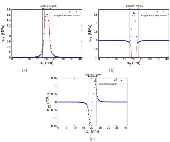
(30) Thèse de Gabriel Franck Bouobda Moladje, Université de Lille, 2020. 2.1. BIBLIOGRAPHY. CHAPTER 2. ELASTODIFFUSION. The ability of microstructural defects to absorb PDs (sink strength) is a key parameter to better understand and predict the evolution of these microstructural defects under irradiation. This ability strongly depends on the elastic interactions between sinks and PDs. The sink strength is computed in this chapter for different microstructural defects (edge dislocations, array of edge dislocations and cavities) by using a PF approach. The computations include the elastic interactions and the modification of the PD migration rate by a strain field.. 2.1 2.1.1. Bibliography Sink strength: definition and calculations. Under irradiation point defects (PD), vacancies and self-interstitial atoms (SIAs), are created and diffuse towards microstructural defects such as dislocations, grain boundaries, cavities, etc. These microstructural defects will evolve according to their ability to absorb PD, also known as sink strength. The sink strength can be calculated using different methods: by the analytical solution of the PD diffusion equation around the considered sink [27, 32], by performing object kinetic Monte Carlo (OKMC) simulations [33, 34, 35], or by using a phase field (PF) approach [4, 36, 37, 38]. In the methods presented below, the PD diffusion is considered isotropic in an unstrained system. In the rate theory models of irradiated materials [27, 10], the kinetic equations are ¯ d of PD d: related to the average atomic fraction X ¯V X dX 2 s ¯VX ¯I − ¯ = K0V − RVI X ks, V DV (XV − XV ) dt s. (2.1). ¯I X dX 2 s ¯VX ¯I − ¯ = K0I − RVI X ks, I DI (XI − XI ) dt s. (2.2). where V and I refer respectively to vacancies and SIAs. Kd0 is the generation rate of PD d (d = V, I), RVI is the rate of mutual recombination between PD and is related to the PD diffusion coefficient Dd through the relation: RVI =. 4πrc (DV + DI ) Vat. (2.3). with rc the distance of recombination and Vat the atomic volume. Xsd is the atomic fraction of PD d at sink s. k2s,d is the sink strength of sink s for PD d. ¯. Xd At steady state (t → ∞), ddt = 0. Equations 2.1 and 2.2 become, by assuming the recombination term negligible and considering one type of sink: 2 ¯ d (t → ∞) − X s ) = 0 K0d − ks,d Dd (X d. (2.4). which leads to the following expression of the sink strength: 2 ks,d =. K0d ¯ d (t → ∞) − X s ) Dd (X d. (2.5). 30. © 2020 Tous droits réservés.. lilliad.univ-lille.fr.
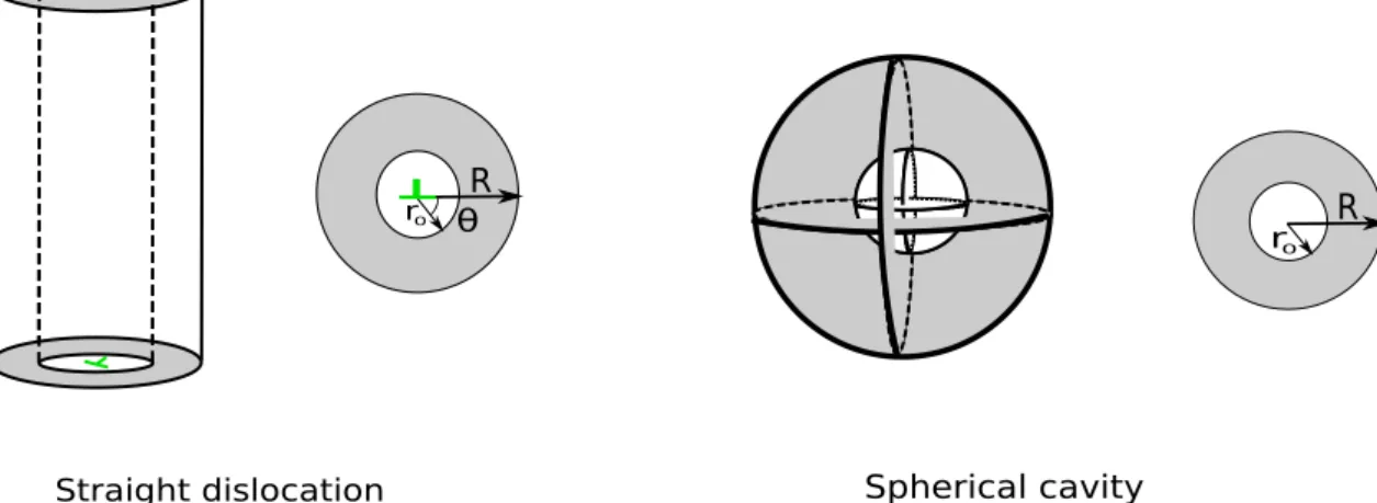
(31) Thèse de Gabriel Franck Bouobda Moladje, Université de Lille, 2020. CHAPTER 2. ELASTODIFFUSION. 2.1. BIBLIOGRAPHY. ¯ d (t → ∞) depends on the shape and volume The average atomic fraction at steady state X of the sink, on the sink free region shape and volume, on the diffusion rate properties of PD, and on the possible elastic interactions between PD and sink. Several analytical expressions of the sink strength for various sinks have been obtained by solving equations 2.1 and 2.2 using different boundary conditions [27]. In table 2.1 the analytical solutions of the sink strength of a straight dislocation and a spherical cavity are given. The sink of radius r0 is contained in a region or reservoir of radius R free of any other sink as illustrated in Fig. 2.1. The reservoir has the same symmetry as the sink. In the models of Laplace,. (. r0. R θ. r0. R. Spherical cavity. Straight dislocation. Figure 2.1: Sink geometry for analytical solutions of the sink strength (cylindrical and spherical symmetry for straight dislocation and cavity respectively). Poisson and Wiedersich, the sink strength is obtained when the elastic interactions between PD and sink are neglected. Wiedersich’s model is known to be more realistic than the models of Laplace and Poisson [27, 4]. The difficulty in the analytical models is to incorporate the elastic interactions. When the elastic interactions are taken into account, the system energy is modified as well as the PD migration energy (elastodiffusion) as described in sections 2.1.2 and 2.2.2. The model proposed by Rauh and Simon [32] for the sink strength calculation of edge dislocations takes into account the elastic interactions through an elastic drift term in the diffusion equation (see table 2.1). In this formulation, only the system energy is affected by the elastic interactions. The PD migration rate remains unchanged. The model of Rauh is limited to isotropic systems and PDs. In the case of a spherical cavity in an isotropic medium, Borodin et al. [39] have proposed a solution which incorporates the elastic interactions. The strain field generated by a spherical cavity in an isotropic medium verifies Tr(εij ) = 0 [40, 39]. As Tr(εij ) = 0, the elastic energy in the stable state given by E = -Peij εij in the case of isotropic PD (Peij = Pe0 δij ) is then zero. Peij is the PD elastic dipole tensor at the stable configuration described in section 2.1.2. The elastic drift term is consequently zero but still, some elastic interactions remain and are taken into account through the PD migration rate (see table 2.1). The PD diffusion tensor has been rewritten in order to introduce the elastic interactions between PDs and the cavity. The model is based on the one of Dederichs and Schroeder [41] (see section 2.1.2) who first proposed a model of PD diffusion in stressed systems. It must be pointed out that the solution of Borodin is very simple, it depends on the elastic dipole tensor 31. © 2020 Tous droits réservés.. lilliad.univ-lille.fr.
(32) Thèse de Gabriel Franck Bouobda Moladje, Université de Lille, 2020. P h. hi hj. P αβ. P kl. Equation. µb(1+ν)Ωd 3π(1−ν)kB T. + K0 = 0, sad h Pkl ( αβ ) sad )] exp[− 1 E 0 (h )] kB T εkl (r kB T m αβ. ∂X ∂ ∂xi Dij ∂xj. [1 +. k 2 /ρ spherical cavity (fd = (r0 /R)2 ). 4πr0 R R−r0. 4πr0 R R−r0. 2π , )+ 21 (fd −1). 2π −1/2 , ln(fd ). −1/2. ln(fd. 3/2 4πr (1−fd ) 0 1/2 3/2 +fd −0.2fd3. 1−1.8fd. (−1)n zn (R),. n=1. ∞ P. k 2 /ρ. 2π(1−fd ) , )− 43 + 41 fd (4−fd ). −1/2. z0 (R) + 2. 2γ r0 )],. 2πIn (L/2r0 )In (L/2R) In (L/2r0 )Kn (L/2R)−In (L/2R)Kn (L/2r0 ). k 2 /ρ. 4πR[1 + q(p −. 3 kB T N Z. h αβ. PP. sad (h ) ei ej Pkl αβ. −d1122 −2d2323 ) , q = − 5(2d2323 )+2(d1111 40µ. zn (R) =. ln(fd. Straight dislocation,. Table 2.1: Analytical solutions of the sink strength for a straight dislocation and a spherical cavity. r0 is the sink radius and R the reservoir radius. ρ is the sink density equal to (πR2 )−1 for a straight dislocation and ( 34 πR3 )−1 for a spherical cavity. No elastic interactions Equation D∇2 X = 0. (X(r = R) fixed). (X(r = R) fixed). Laplace D∇2 X + K0 = 0. ν0 2Z. Spherical cavity (no elastic drift term and elastodiffusion1 ). µel (r, θ) = L sinr θ , L =. D∇2 X + ∇[X∇µel ] = 0,. Straight dislocation (elastic drift term and no elastodiffusion1 ) Equation. Elastic interactions. D∇2 X + K0 = 0. Poisson Wiedersich. Rauh and Simon [32]. Borodin et al. [39] Dij =. dijkl =. µ is the shear modulus, ν the Poisson ratio, T the temperature, kB the Boltzmann constant, b the length of the Burgers vector, Ωd the relaxation volume of the PD d, In and Kn are the modified Bessel functions of the nth order of the first and second kind respectively (Rauh and Simon [32]), h p the internal gas pressure, r0 the cavity radius, γ the surface tension of the cavity, Pijsad (αβ ) the elastic dipole tensor at saddle state, εij (r) the strain field due to the cavity, h the possible jump direction, e the unit vector in the jump direction, α and β the possible PD orientations in the initial and 0 h final stable configuration respectively, N the number of nearest neighbour sites, Z the number of pairs (α, β), ν0 the jump frequency and Em (αβ ) the PD migration energy in unstrained system. (Borodin et al. [39]) Elastodiffusion1 : PD migration energy modified by a strain field.. 32. lilliad.univ-lille.fr. © 2020 Tous droits réservés.. CHAPTER 2. ELASTODIFFUSION 2.1. BIBLIOGRAPHY.
(33) Thèse de Gabriel Franck Bouobda Moladje, Université de Lille, 2020. CHAPTER 2. ELASTODIFFUSION. 2.1. BIBLIOGRAPHY. of PD at saddle point and varies as 1/r0 (see table 2.1). Like in the model of Rauh, the model of Borodin et al. is limited to isotropic systems. In the OKMC simulations, different methods [34, 35, 42, 33] exist to calculate the sink strength. One of them [34, 35] consists in the following. A sink is located in a 3-dimensional box with periodic boundary conditions. PDs are generated uniformly at a constant rate K0 and migrate in the box by successive atomic jumps until they are absorbed by the sink. The sink is assumed immobile and does not evolve by absorption of PDs. The recombination of PDs and their emission by the sink are neglected. The possible events are the creation of PD or an atomic jump from a stable position to a neighboring one. The next event is chosen according to the residence time algorithm [15, 16]. The sink strength is calculated when the steady state is reached and is given by: 2 ks,d =. K0 ¯d Dd N. (2.6). ¯ d is the average number of PD d still present in the box. In the other method where N [42, 33], one migrating PD is present in the simulation box containing a sink at a given time. The PD trajectory is followed before it’s absorbed by the sink. A new PD of the same type is introduced after the previous one has been absorbed. The sink strength is obtained as: 2Ndim 2 (2.7) ks,d = 2 d <n> where Ndim is the PD migration dimensionality, d the jump length and <n> the average number of jumps before the absorption. The PF approach to compute the sink strength is detailed in section 2.2 and the obtained expression is similar to equations 2.4 and 2.5. Another interesting quantity is the sink bias Bs defined as [43]: 2 ks,v Bs = 1 − 2 ks,i. (2.8). The sink bias allows explaining irradiation dislocation loop growth/shrinkage, irradiation void swelling, or irradiation creep [44, 28, 45]. For example, straight dislocations are known to be biased: SIAs are more absorbed than vacancies. Voids are known to produce shorter range stress fields and are usually considered as neutral sinks i.e. they absorb the same amount of vacancies and SIAs if they are produced or available at the same rate [10]. The preferential absorption of SIAs by the dislocations leads to a net flux of vacancies to voids and thus to void growth mechanism known as irradiation swelling. The main advantage of the OKMC and PF simulations compared to the analytical solutions is the possibility to take into account the elastic interactions and anisotropic diffusion in complex microstructures. In this section, the sink strength has been defined and the methods which allow to calculate it have also been presented. It has been shown that elastic interactions that may exist between sinks and PDs modify the sink strength. Thus to correctly calculate the sink strength, these elastic interactions must be properly described. In section 2.1.2, we present how a strain field which can be due to a sink modifies the. 33. © 2020 Tous droits réservés.. lilliad.univ-lille.fr.
(34) Thèse de Gabriel Franck Bouobda Moladje, Université de Lille, 2020. 2.1. BIBLIOGRAPHY. CHAPTER 2. ELASTODIFFUSION. PD diffusion.. 2.1.2. PD diffusion modified by the sink strain field. During the diffusion of PDs towards the sink, there are elastic interactions between PD and the stress field produced by the sink. As a consequence, the system energy is modified and includes an elastic energy which acts as a driving force for PD diffusion. Moreover, the migration energy of PD is also modified by the stress field, this dependence being called elastodiffusion. Elastodiffusion has first been investigated by Dederichs and Schroeder [41]. Considering a crystal and PD with cubic symmetry, the PD diffusion tensor in the unstrained system is given by: N 2 h ν exp(−βE0m )δij (2.9) 6 with δij the Kronecker symbol and β = 1/kB T . N is the number of nearest neighbour sites, ν the attempt frequency, h the jump length. Em 0 is the PD migration energy which is the difference between the energy at the saddle and stable configurations: 0 Dij =. sad e Em 0 = E0 − E0. (2.10). In the presence of an elastic field εkl (r) due to the sink, the saddle and stable point energies are modified as follows at the first order (differences in the elastic properties between those of the PD and those of the matrix are neglected): Ee = Ee0 −. X e ¯. Pkl εkl (re ). (2.11). kl. Esad = Esad 0 −. X. sad Psad ) kl (h)εkl (r. (2.12). kl. Em = Esad − Ee = Em 0 −[. X. sad Psad )− kl (h)εkl (r. X e ¯. Pkl εkl (re )]. kl. (2.13). kl. where Pekl and Psad kl (h) are respectively the elastic dipole tensors of PD at stable and saddle point for the jump direction h. The PD anisotropy at stable point is ignored in this model, ¯ e instead of Pe where P ¯ e is given by: which justifies the choice of P kl kl kl ¯ e = Tr(Pe )δkl /3, Tr(Pij ) = P kl kl. X. Pij. (2.14). i,j(i=j). It can then be demonstrated that the PD diffusion tensor is as follows: Dij (r) =. h2 ν X h h u u exp(−βE m ) 2 h i j. (2.15). with uhi the ith component of unit vector in the direction of the jump h. Using the expression given by Eq. 2.13, the diffusion tensor becomes: Dij (r) =. X h2 ν X h h sad e ui uj exp(−βE0m ) exp[β (Pkl (h) − P¯kl )εkl (re )] 2 h kl. (2.16). 34. © 2020 Tous droits réservés.. lilliad.univ-lille.fr.
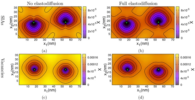
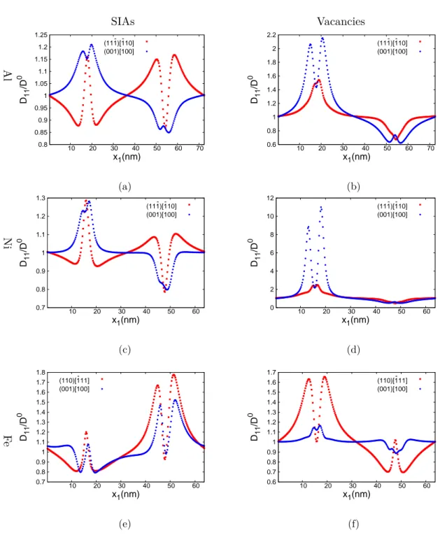
(35) Thèse de Gabriel Franck Bouobda Moladje, Université de Lille, 2020. CHAPTER 2. ELASTODIFFUSION. 2.1. BIBLIOGRAPHY. assuming that εkl (rsad ) ' εkl (re ). This new diffusion tensor can be expressed as a function of the unstrained diffusion coefficient D0 : Dij (r) =. X 3D0 X h h sad e ui uj exp[β (Pkl (h) − P¯kl )εkl (re )] N h kl. (2.17). sad (h) = P sad , with D0 = N6 h2 ν exp(−βE0m ). In the case of isotropic PD at saddle point, Pkl kl relation 2.17 leads then to a diagonal diffusion tensor:. Dij (r) =. X X 3D0 sad e exp[β (Pkl − P¯kl )εkl (re )] uhi uhj N kl h. (2.18). since X. uhi uhj = 0,. if. i 6= j.. (2.19). h. On the contrary, for anisotropic PD at saddle point, Dij can have off-diagonal terms whereas D0ij does not. In the case where Psad kl depends on the initial and final PD orientations, a similar expression of Eq. 2.17 is obtained: Dij (r) =. X 3D0 X X h h sad h e ui uj exp[β (Pkl (ξψ ) − P¯kl )εkl (re )] N Z h ξψ kl. (2.20). where ξ and ψ refer respectively to the PD orientation in the initial and final stable configurations and Z is the number of pairs (ξ,ψ). The Pij -tensors can be determined from atomistic calculations. For this purpose, a perfect simulation cell of volume V with periodic boundary conditions is considered. One PD is introduced in the box and the supercell vectors are kept fixed. After atomic relaxation, the Pij -tensors are deduced from the residual stress σij induced by the PD on the box through the relation [46, 34, 35]: 0 Pij = V(σij − σij ). (2.21). 0 is the residual stress on the perfect supercell after relaxation. Generally, σ 0 is where σij ij not zero due to the finite convergence criteria used for the simulations. An alternative though more time consuming way is to determine Pij from the strain field of the supercell if it is allowed to relax in volume and shape (see Eq. 2.25 for instance). The elastic dipole tensors can be also determined from experiments, but requires a combination of several experimental techniques [35]. The elastodiffusion effects on sink strength of various sink types have been investigated analytically [47] and using OKMC simulations [46, 34]. The results obtained mainly show that taking into account elastodiffusion can have significant effects on the sink strength. Skinner and Woo [47] have studied the elastodiffusion effects on sink strength of edge dislocations in fcc copper and bcc iron. They performed analytical calculations in the case of isotropic and anisotropic PD at saddle point. Their results showed the increase of sink strength with the PD anisotropy for both materials and the effects are more important for high dislocation densities. The PD anisotropy effects are more pronounced for vacancies than SIAs in copper while the effects are comparable for both PDs in iron. The results. 35. © 2020 Tous droits réservés.. lilliad.univ-lille.fr.
(36) Thèse de Gabriel Franck Bouobda Moladje, Université de Lille, 2020. 2.2. PF METHODOLOGY. CHAPTER 2. ELASTODIFFUSION. obtained by Carpentier et al. [34] using OKMC simulations in Al are qualitatively the same of that obtained in copper by Skinner for edge dislocations. Carpentier et al. have also performed the OKMC simulations in the case of a spherical cavity. The results revealed the increase of the sink strength with the PD anisotropy at saddle point which leads to a cavity bias around 30 %, whereas cavity is commonly considered as an unbiased sink. Elastodiffusion effects on sink strength of grain boundaries have also been investigated by Vattré et al. [46]. In this case, the effects are visible for high grain boundary densities. The studies of Vattré [46] and Carpentier [34] also showed that the PD trajectory towards the sink is modified when elastodiffusion is taken into account. All these results show that the elastodiffusion effects on sink strength and PD trajectories depend on several parameters such as: the Pij -tensors anisotropy at saddle point, the crystal anisotropy, the sink strain field properties, etc. The elastodiffusion has been described in this section. Thus, in addition to the elastic drift term, the elastodiffusion allows to take into account the elastic effects in the PD diffusion tensor. A comparison of the sink strength calculations without and with elastodiffusion will allow to quantify the elastodiffusion effects on the sink strength. For that, we use a PF approach whose description is given in the following section (section 2.2).. 2.2. PF methodology. A single crystal is considered in which one type of sink is introduced. The production of PDs is simulated through a generation rate term. PD will diffuse inside the matrix and will be absorbed by the sink. To describe the system evolution, the order parameters, the total free energy of the system and the evolution equations are defined successively, as usually done in a PF approach.. 2.2.1. Order parameters. The necessary order parameters to describe the system evolution are the following:. •. The site fractions of PDs Xd , d = I for SIAs or V for vacancies. PDs are created at a uniform and constant generation rate K0 (s−1 ).. •. The elastic shape function ηs associated to the sink s and which allows to generate the corresponding stress field.. •. The shape function λs of the capture zone of sink s (equal to 0 inside the matrix and 1 in the capture zone). This parameter allows a precise control of the sink geometry, which is essential to correctly calculate the sink strength.. 2.2.2. Energy of the system. The system evolves by minimisation of the total free energy F. Strictly speaking, this is only true close enough to equilibrium, an hypothesis that we assume in the following. F 36. © 2020 Tous droits réservés.. lilliad.univ-lille.fr.
(37) Thèse de Gabriel Franck Bouobda Moladje, Université de Lille, 2020. CHAPTER 2. ELASTODIFFUSION. 2.2. PF METHODOLOGY. includes the chemical free energy Fchem associated to PD and the elastic energy Fel : F (Xd , ηs ) = Fchem (Xd ) + Fel (Xd , ηs ). (2.22). In our system description, the sink evolution due to the PD absorption is not taken into account, and the sink is assumed unchanged and immobile. This assumption justifies the fact that the self-energy associated to the sink is ignored in Eq. 2.22.. Chemical free energy In the limit of dilute systems, the chemical free energy of the system is written as [10]:. Fchem (Xd ) =. Z 1 X Ed Xd + kB T[Xd ln Xd + (1 − Xd ) ln(1 − Xd )]dV Vat d V f. (2.23). where Edf is the PD formation energy and V is the volume of the system.. Elastic energy The elastic energy is calculated via the microelasticity theory [26]. It is a function of the elastic strain which is the difference between the total strain εij (r) and the total eigenstrain ε0,tot ij (r). The total eigenstrain is given by: ε0,tot ij (r) =. X 0,X d. εij. 0,ηs ηs (r) Xd (r) + εij. (2.24). d s d are respectively the eigenstrain associated to the PD d and the sink where ε0,X and ε0,η ij ij s. The PD eigenstrain and its dipole tensor at the equilibrium state are connected by the relation: d (2.25) Pije,d = Vat Cijkl ε0,X kl. where Cijkl are the elastic constants of the system. In this manuscript, the system is considered homogeneous which means that the elastic constants are independent of space. The PD relaxation volume Ωd is given by: d Ωd = Vat Tr(ε0,X kl ). (2.26). 0,Xd εkl can be determined from atomic-scale calculations of the Pij tensors (see Eq. 2.25). Elastic equivalences between a given sink and an inclusion are used to determine the s corresponding eigenstrain ε0,η [48, 40]. Examples will be given in section 2.3.1. ij The expression of the elastic energy is as follows:. Fel =. 1 2. Z V. 0,tot Cijkl [εij (r) − ε0,tot ij (r)][εkl (r) − εkl (r)]dV. (2.27). The total strain εij (r) can be decomposed into two parts, the heterogeneous part of the strain δεij (r) and the average strain εij : εij (r) = εij + δεij (r). (2.28). 37. © 2020 Tous droits réservés.. lilliad.univ-lille.fr.
(38) Thèse de Gabriel Franck Bouobda Moladje, Université de Lille, 2020. 2.2. PF METHODOLOGY. CHAPTER 2. ELASTODIFFUSION. it can be demonstrated that in an elastically homogeneous system, εij =. X 0,X d. εij. 0,ηs Xd (r) + εij ηs (r). (2.29). d. The heterogeneous strain δεij (r) derives from the displacement field ui (r), and for small strains is given by: 1 ∂ui ∂uj δεij (r) = [ + ](r) (2.30) 2 ∂rj ∂ri The displacement field is obtained by solving the mechanical equilibrium equation: div σij (r) = 0. (2.31). σij (r) = Cijkl (εkl (r) − ε0,tot kl (r)). (2.32). where σij (r) is the elastic stress:. Eq. 2.31 becomes using Eq.2.32 and Eq.2.30: Cijkl. X ∂ 2 uk (r) ∂Xd 0,ηs ∂ηs d = Cijkl [ ε0,X (r) + εkl (r)] kl ∂rj ∂rl ∂rj ∂rj d. (2.33). The Fourier space is used to solve Eq.2.33 due to its simple form in this space: [Gik (q)]−1 u ˜k (q) = −ic Cijkl [. X 0,X d. εkl. ˜ d (q) + ε0,ηs qj η˜s (q)] qj X kl. (2.34). d. with [Gik (q)]−1 = Cijkl qj ql and ic is the imaginary complex number defined as (ic )2 = −1. φ˜ is the Fourier transform of the field φ and q is the wave vector. Gik (q) is the Fourier transform of the Green function used in anisotropic elasticity. φ˜ is given by: ˜ φ(q) =. Z. φ(r) exp(−ic q.r)dV. (2.35). V. The elastic energy is also computed in the Fourier space and it can be demonstrated that: 1 X 1 XX m 0,θm m 0,θn Fel = V Cijkl ε0,θ Cijkl ε0,θ ij εkl θ m − V ij εkl θ m θ n 2 m 2 m n −. 1 XX 2 m n. Z. d3 q 0,θm 0,θn ˜ qj σij Gik (q)σkl ql θm (q)θ˜n (q) (2.36) (2π)3. 0,θm m where σij = Cijkl ε0,θ kl . θm refers to the order parameter (XI , XV , ηs ) associated to the defect m (I, V, s). The use of the Fourier space implies periodic conditions at the boundaries of the simulation domain.. 38. © 2020 Tous droits réservés.. lilliad.univ-lille.fr.
(39) Thèse de Gabriel Franck Bouobda Moladje, Université de Lille, 2020. CHAPTER 2. ELASTODIFFUSION. 2.2.3. 2.2. PF METHODOLOGY. Kinetic equations. The PD fraction Xd is assumed to be conserved in the matrix and its evolution equation is of a Cahn-Hilliard type. The generation rate term K0 and the absorption term Jabs s,d (r, t) are added in this equation to simulate the PD creation by irradiation and absorption by the sink. The resulting equation is given by: X X ∂Xd δF (Xd , ηs ) abs (r, t) = ∇i .[ Mijd (r, t)∇j (r, t)] + K0 − Js,d (r, t) ∂t δX d i j. (2.37). with Mdij (r, t) the PD mobility tensor of type d which in the case of the simple free energy expressed by Eq. 2.23 can be written as: Mijd (r, t) =. Xd (r, t) d Dij (r) kB T. (2.38). where Ddij is the PD diffusion tensor given by equation 2.20. The recombination between PDs is neglected and the PD diffusion equations are solved independently. Jabs s,d is defined by using the shape function λs as: s Jabs s,d (r, t) = λs (r)λef f (Xd (r, t) − Xd ). (2.39). λef f is an efficiency factor equal to 1/δt in the case of a perfect sink, δt being the time step used to solve the kinetic equation of PDs. Xsd is the atomic fraction of PD inside the sink which is fixed at a constant value usually taken as the thermal equilibrium fraction of the PD since the sink is assumed unchanged. Substituting the total energy into Eq. 2.37 and taking the first variational derivatives with respect to the PD fraction Xd , we obtain: d (r) X X Dij ∂Xd (r, t) = ∇i [ Xd (r, t)∇j (µdchem (r, t) + µdel (r, t))] + K0 − Jabs s,d (r, t) (2.40) ∂t V k T at B i j. where µdchem = Vat. δFchem δXd. (2.41). In the low PD fraction approximation: µdchem = Ef + kB T ln Xd µdel = Vat. δFel δXd. (2.42). (2.43). µdel is calculated in the Fourier space and has the following simple form: ˜ I (q) + BIV (q)X ˜ V (q) + BIηs (q)˜ µ ˜Iel (q) = BII (q)X η (q). (2.44). ˜ V (q) + BVI (q)X ˜ I (q) + BVηs (q)˜ µ ˜Vel (q) = BVV (q)X η (q). (2.45). where 39. © 2020 Tous droits réservés.. lilliad.univ-lille.fr.
(40) Thèse de Gabriel Franck Bouobda Moladje, Université de Lille, 2020. 2.2. PF METHODOLOGY. . CHAPTER 2. ELASTODIFFUSION. 0,XI 0,XI − qj σij0,XI Gik (q)σkl ql BII (q) = σij0,XI εij 0,XV 0,XV BVV (q) = σij0,XV εij − qj σij0,XV Gik (q)σkl ql 0,XV 0,XV BIV (q) = σij0,XI εij − qj σij0,XI Gik (q)σkl ql 0,XI 0,XI BVI (q) = σij0,XV εij − qj σij0,XV Gik (q)σkl ql. (2.46). 0,XI 0,ηs BIηs (q) = σij0,XI ε0,η ij − qj σij Gik (q)σkl ql 0,ηs 0,XV Gik (q)σkl ql BVηs (q) = σij0,XV ε0,η ij − qj σij. The local PD flux Jd , which is a function of driving forces is given by: Jid (r, t) = −. d (r)X (r, t) X Dij d. Vat kB T. j. ∇j (µdchem (r, t) + µdel (r, t)). (2.47). The evolution equations of the order parameters ηs and λs are not required due to the fact that they do not evolve. The sink strength k2s,d can be deduced from Eq. 2.40 when steady state is reached. It is a function of the absorption rate Js,d and the average site fraction Xd [10]: Js,d 2 (2.48) ks,d = 0,d D (X d − Xds ) with. 1 Js,d = Jabs (r, t)dV (2.49) V V s,d To solve equation 2.40, the following dimensionless parameters are introduced: Z. . r∗ = r/a0 ,. ∇∗i = a0 ∇i. d,∗ d /D 0,d Dij = Dij. t∗ = t/t0 ,. K0∗ abs,∗ Js,d C∗ ijkl. t0 = a20 /D0,d. (2.50). = t0 K0 abs = t0 Js,d. = Cijkl /( kVBatT ),. µ∗ =. µ kB T. where a0 is the length of a unit PF cell. The dimensionless form of Eq. 2.40 is given by: X X d,∗ ∂Xd ∗ ∗ d,∗ ∗ ∗ abs,∗ ∗ ∗ ∗ ∗ ∗ ∗ (r , t ) = ∇ [ Dij (r∗ )Xd ∇∗j (µd,∗ i chem (r , t ) + µel (r , t ))] + K0 − Js,d (r , t ) ∂t∗ i j. (2.51) Specific numerical schemes and algorithms are required to treat Eq. 2.51. More details on this issue are given in Appendix A.. 40. © 2020 Tous droits réservés.. lilliad.univ-lille.fr.
Figure
![Figure 1.3: Illustration of a) an edge dislocation and b) a screw dislocation [9] in a simple cubic crystal.](https://thumb-eu.123doks.com/thumbv2/123doknet/3519794.102967/23.892.200.708.161.423/figure-illustration-dislocation-screw-dislocation-simple-cubic-crystal.webp)
![Figure 1.4: Dislocation loops observed for irradiation temperatures of 623-773 K in neutron-irradiated iron, transmission electron microscopy (TEM) observations (from [11]).](https://thumb-eu.123doks.com/thumbv2/123doknet/3519794.102967/24.892.208.689.170.359/dislocation-observed-irradiation-temperatures-irradiated-transmission-microscopy-observations.webp)
+7
Documents relatifs