A Projective approach to handle 3D spatial data
Roland Billen
Department of Geography and Geomatics, Centre for Geosciences, University of Glasgow, Glasgow G12 8QQ
Tel. +44 (0) 141 3302289 Fax +44 (0) 141 3304894
[email protected]://www.geog.gla.ac.uk/~rbillen/
1. Introduction
The choice of relevant data models and data structures is still an important issue in 3D GIS. In the 3D urban GIS context, boundary representation models are usually adopted with different levels of “topology” integration (Molenaar, 1990; Zlatanova, 2000; Pfund, 2001). In this work, a new approach based on projective properties of spatial objects has been adopted. The theoretical framework behind this is the Dimensional Model (DM), whose originality is to be defined in a projective space instead of a topological space. This model proposes a new partition of the spatial objects, called dimensional
elements, and a new type of spatial relationships, the dimensional relationships. The aim of the study
is to define spatial data models, and after that data structures, based on the DM theoretical framework, allowing the extraction of the dimensional relationships without point co-ordinate computations. The results are three boundary representation models called Spatial Dimensional Data Models (SDDM), which present interesting properties for 3D modelling.
2. Dimensional Model
The Dimensional Model (DM) is a new theoretical spatial model based on projective characteristics of objects (Billen, 2002; Billen et al., 2002). The basic motivation for this model is to mathematically express spatial relationships that are not differentiated by topological relationships models. These new relationships (called dimensional relationships) are especially important in 3D spatial analysis. The starting point of the model is the definition of the order of points of an object. This well-known concept in convex geometry (Bronsted, 1983) has been extended for n-manifold. Figure 1a presents an intuitive understanding of this concept in the case of a cube. After that, a new object’s partition (called dimensional elements) based on the order of points is proposed. In brief, the α-dimensional element (denoted αD-element) of a spatial object C has an extension which is the subset of C formed by its points of order α. The dimensional relationships are defined as the relationships existing between dimensional elements. The spatial relationship between two objects can be expressed by the dimensional relationships that exist between the dimensional elements of both objects. We will not develop further these concepts but the figure 1b gives a good example of spatial configurations between two objects which are differentiated within the DM when considering dimensional relationships (but which are topologically equivalent).
a. Order of points of a cube b. Three distinct spatial configurations within the DM
Figure 1. Some DM characteristics
3. Derived Spatial Data Models
As topological data models link geometric primitives and a topological partition of space with topological primitives, so a DM oriented data model should link geometric primitives and dimensional elements with “projective” primitives (denoted Proj αD). These primitives must have the
necessary projective characteristics that allow the extraction of the dimensional elements of the spatial objects. This leads to the two main principles of projective modelling which are presented in the next section.
3.1 Principles
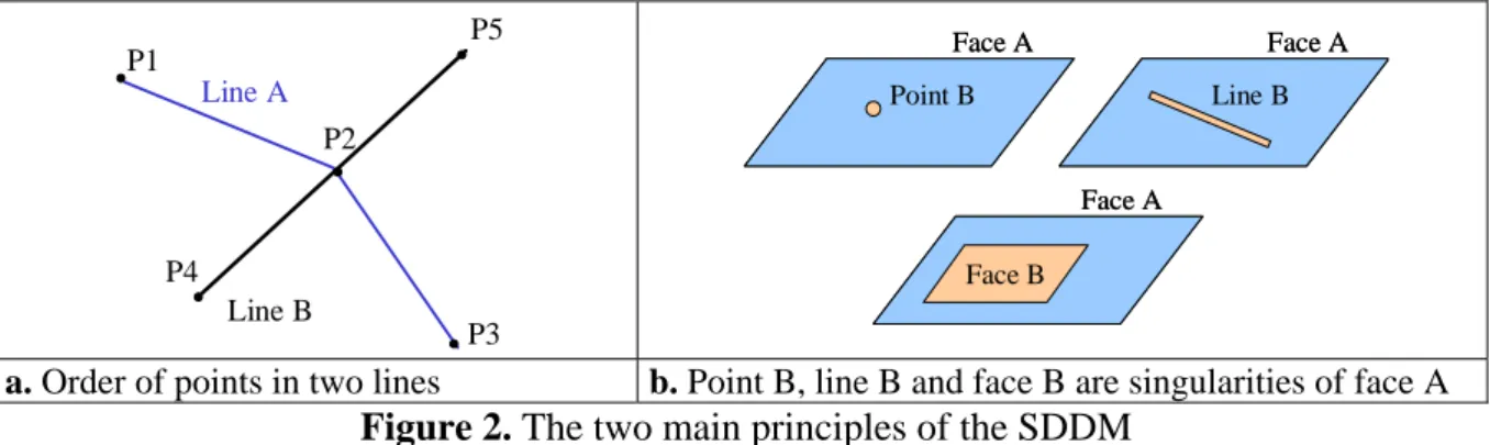
Principle 1: A projective primitive of dimension n of a spatial object must be part of the n-D element of this spatial object.
The figure 2a illustrates that principle. In the case of the line A, all the geometric primitives of dimension 0 (points P1, P2 and P3) have order 0. They form all together the 0D-element of the line. They are therefore Proj 0D primitives. In the line B, we can see that one of the points (P2) is aligned with the two extreme points (P4 and P5), this point has order 1 with regard to the DM rules. So this point cannot be a Proj 0D of the line B, which will be defined only by P4 and P5.
Principle 2: Two projective primitives can share a common space.
Two projective primitives that share common space are bound by a relationship called singularity. Singularity concepts have been introduced in some topological models, but in those cases, only primitives of lower dimension can be singularities of primitives of higher dimension (example: a node lying in a face without being part of the definition of this face) (Molenaar, 1990; Zlatanova, 2000; Mesgari, 2002). In this approach, singularity may bind primitives of the same dimension. In our previous example, the point P2 is a singularity of the line B. Figure 2b illustrates singularity relationships between primitives of different dimensions.
P1 P2 P5 P3 P4 Line B Line A
a. Order of points in two lines b. Point B, line B and face B are singularities of face A
Face B Face A Face A Face A Point B Line B Face B Face A Face A Face A Point B Line B
Figure 2. The two main principles of the SDDM
3.2 General Spatial Dimensional Data Model
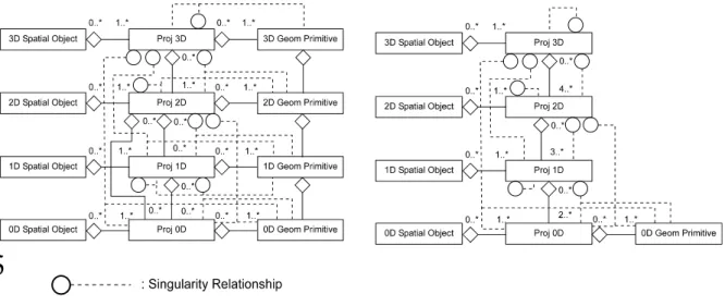
The general SDDM is a boundary representation model, where geometric primitives of dimension 0, 1, 2 and 3 compose projective primitives, i.e. Proj 0D, Proj 1D, Proj 2D and Proj 3D that define the spatial objects (see figure 3a). The geometric primitives are those presented in the OGC specifications. The general SDDM can be seen as a projective package that parallels a geometric package. Each projective primitive is built either from lower projective primitives or directly from geometric primitives. Projective primitives have a very general definition that corresponds to spatial manifolds. The extraction of dimensional relationships is simple.
3.3 Advanced Spatial Dimensional Data Model
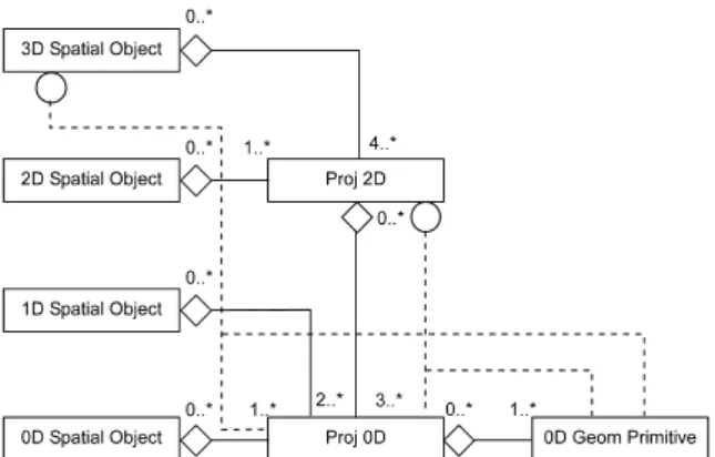
In the advanced SDDM (figure 3b), only the 0D geometric primitive remains. It can compose the Proj 0D primitive or be part of a singularity relationship with any projective primitive. Only planar Proj 2D and straight line Proj 1D are allowed. However, this simplification is rather common in 3D modelling. The determination of dimensional relationships is still easy. Only the determination of the intersection’s dimension between dimensional elements needs more complex algorithms.
a. General SDDM b. Advanced SDDM
Figure 3. SDDM Conceptual data models
Cube 1
Cube 2
With 3D FDS a40: 31, 32 a41: 31, 34 a42: 42, 43 a43: 43, 44 a44: 44, 34 a45: 32, 42 Proj 3DProj 2D Proj 1D Singularity
With SDDM - advanced
Figure 4. Comparison of 3D FDS and SDDM – advanced.
Let us consider two cubes (cube 1 and cube 2) that overlap (the intersection is the cube bounded by points 3, 43, 44, 34, 31, 32, 42, 15). The colour red means that the element is not present in the basic description of the two cubes alone, but is the result of their overlap. A 3D FDS (Molenaar, 1990) description of this situation shows that the constituent elements are influenced by the overlap (creation of new elements, division of existing element). The cube 1 has now 11 faces. Using SDDM (advanced), the constitutive elements are not influenced by the overlap and the basic geometry is maintained (cube 1 has 8 “faces”); new relations appear as singularities.
3.4 Simplified Spatial Dimensional Data Model
The simplified SDDM is a practical solution (figure 5), which seems to be relevant for 3D modelling. As in other 3D data models (Zlatanova, 2000), the 1D primitive (in our case Proj 1D) has been removed from the model. Its removal accelerates the computational processes. The Proj 3D is also removed and only simple 3D spatial objects are allowed. The determination of dimensional relationships is more complex (because only 0D and 2D projective primitives remain explicitly). This solution has been implemented in Oracle 9i, and operators have been developed in PL/SQL for the extraction of the dimensional relationships such as the reconstruction and visualisation of the objects and their intersections.
Figure 5. Conceptual data model of the simplified SDDM
4. Conclusions
The main benefits of the approach could be said to be:
- Spatial objects are defined in terms of their projective characteristics, which correspond to the simplest set of data needed for their reconstruction; this is surely one of the most important characteristics needed for 3D modelling.
- The model gives a clear definition of singularities, and basic primitives can contain singularities of the same or lower dimension;
- The dimensional relationships can be extracted without point co-ordinate computations. Other aspects still to be explored include the benefit of the models for dynamic modelling.
References
Billen, R. (2002). Nouvelle perception de la spatialité des objets et de leurs relations –
Développement d’une modélisation tridimensionnelle de l’information spatiale, PhD. Thesis.
Billen, R., Zlatanova, S., Mathonet, P., and Boniver F. (2002), The Dimensional Model: a
framework to distinguish spatial relationships. In: Advances in Spatial Data Handling, Richardson, D., and Van Oosterom P., (eds). Heidelberg: Springer-Verlag, pp. 285-298.
Brondsted, A. (1983). An introduction to convex polytopes (New York: Springer-Verlag).
Mesgari, S. (2000). Topological Cell-Tuple Structures for Three-Dimensional Spatial Data, PhD.
Thesis, ITC dissertation Series, n°74.
Molenaar, M. (1990), A formal data structure for three dimensional vectors maps, Proccedings of the
4th International symposium on spatial data handling, Zurich, pp. 830-843.
Pfund, M. (2001) Topological data structure for a 3D GIS, In Proceedings of the ISPRS « Dynamic
and Multi-Dimensional GIS », Bangkok, 23-25 may, volume 34, pp. 233-237.
Zlatanova, S. (2000). 3D GIS for Urban Development, PhD. Thesis, ITC dissertation Series, n°69. Biography
Roland Billen lectures in Geomatics at the University of Glasgow. His PhD is from the University of Liege, Belgium. His research interests focus on 3D GIS, 3D data structures and Spatial Reasoning.