HAL Id: hal-01150416
https://hal.archives-ouvertes.fr/hal-01150416
Submitted on 11 May 2015HAL is a multi-disciplinary open access archive for the deposit and dissemination of sci-entific research documents, whether they are pub-lished or not. The documents may come from teaching and research institutions in France or abroad, or from public or private research centers.
L’archive ouverte pluridisciplinaire HAL, est destinée au dépôt et à la diffusion de documents scientifiques de niveau recherche, publiés ou non, émanant des établissements d’enseignement et de recherche français ou étrangers, des laboratoires publics ou privés.
Distributed under a Creative Commons Attribution - NonCommercial - ShareAlike| 4.0
Metal-doped apatitic calcium phosphates: preparation,
characterization, and reactivity in the removal of
hydrogen sulfide from gas phase
Sonia Stita, Marta Galera Martinez, Huynh Pham Xuan, Doan Pham Minh,
Ange Nzihou, Patrick Sharrock
To cite this version:
Sonia Stita, Marta Galera Martinez, Huynh Pham Xuan, Doan Pham Minh, Ange Nzihou, et al.. Metal-doped apatitic calcium phosphates: preparation, characterization, and reactivity in the removal of hydrogen sulfide from gas phase. Composite Interfaces , VSP, 2015, pp.1-22. �10.1080/09276440.2015.1049096�. �hal-01150416�
Metal-doped apatitic calcium phosphates: preparation, characterization,
and reactivity in the removal of hydrogen sulfide from gas phase
Sonia STITA1, Marta GALERA MARTINEZ1, Huynh PHAM XUAN1,2, Doan PHAM MINH1*, Ange NZIHOU1, Patrick SHARROCK1
1
Université de Toulouse, Mines Albi, CNRS UMR 5302, Centre RAPSODEE, Campus Jarlard, F–81013 Albi cedex 09, France
2
Actual address: Renewable Energy Department, University of Science and Technology of Hanoi, Vietnam
*Corresponding authors: Email: doan.phammin@mines-albi.fr, Tel: +33563493258.
Keywords: Hydroxyapatite; Metal deposition; Inorganic composite; Sorption; H2S removal
Abstract. With the expansion of human activities, there are more and more living areas
adjacent to industrial and/or agricultural activities such as chemical processes, petroleum processes, paint finishing, food processing, livestock farming, composting plants etc. Bad odor is part of several nuisances caused by industrial and/or agricultural activities. Hydrogen sulfide (H2S) is a typical odorous molecule which causes foul odor at very low concentration.
This molecule is formed in different industrial installations, in particular in coal combustion, and petrochemical refinery. The separation and/or transformation of H2S from gas phase to
odorless products are important processes for sustainable development.
In this paper, we communicate the preparation of new sorbents for the sorption of H2S
from a synthetic gas effluent. These sorbents consist in an inorganic phase (hydroxyapatite) as host particles, and well-dispersed particles of a metal oxide as guest particles which are the active phase for the removal of H2S. At room conditions, iron, lead and zinc doped calcium
phosphates were found to be effective for the removal of H2S. The performance of the
sorbents depends on preparation method and the nature of active phases. This opens new prospects for the treatment of H2S from gas phase.
1. Introduction
Hydrogen sulfide (H2S), a simple chemical molecule, is considered to be one of the
surface water, groundwater, soil, sediment etc. It can be found in different natural sources such as volcanic gas, geysers, sulphurous lakes etc. Nowadays, natural gas, biogas, and syngas being considered as important energy sources or raw materials (for syngas and hydrogen production), contain also H2S at various concentrations, and need pre-treatment
before being processed.[1-5] Different industrial processes and rural and agricultural activities generate also waste gases containing H2S, for examples, crude oil refineries, coal combustion
and/or gasification, paper mills, food industries, wastewater treatment plants, animal farms, etc. At high concentration, the Claus process and its derivatives were developed for the recovery of sulphur.[6] At lower concentration, several methods for H2S treatment and/or
purification were developed. Biological processes call for the use of bacteria, such as
Thiobacillus and Sulfolobus, for the oxidation of H2S into elemental sulphur or sulphate.[7-9] However, these processes require strict operational conditions (temperature, pressure, input composition for energy source…).[10,11] Catalytic processes usually consist of the oxidation of H2S over solid catalysts, in order to convert it to molecular sulphur, sulphide, thiosulfate,
and sulphate.[12-14] Absorption and adsorption are also strongly developed for the elimination of H2S. Absorption refers to the process by which one substance (absorbent), such
as a solid or a liquid, takes up H2S in liquid or gas phase. Amine solutions are commonly used
for the removal of H2S from natural gas. They are attractive because of the potential for high
removal efficiencies, their ability to be selective for H2S abatement, and their regeneration
possibility.[15-17] Adsorption relates to the fixation of H2S on the surface of a solid by weak
physical or physicochemical bonds. Different adsorbents having high reactivity, such as activated carbon, zeolites, modified alumina or other metal oxides, have been investigated for H2S removal process.[2,18-20] As example, Florent and Bandosz investigated the
performance of graphite oxide supported cobalt oxyhydroxyde (CoOOH/C) for the treatment of H2S in moist or dry air.[20] The adsorption capacity of this adsorbent up to reached 69.1
mg g−1. In addition to these standard methods for H2S treatment, hydrate technology has been
developed for H2S separation. Details of this technology can be found elsewhere.[5] This
technology was found to be efficient for cleaning and upgrading the biogas. However, because of their relatively high cost, currently, there has been an increasing interest in utilizing low cost adsorbents which leads to screening industrial wastes, agricultural by-products and natural materials as alternative adsorbents.[21]
This study aims to investigate the reactivity of zinc-, lead-, and iron-doped hydroxyapatites for the removal of H2S from gas phase at room pressure and temperature.
Hydroxyapatite (Ca10(PO4)6(OH)2, called thereafter CaP) can be easily synthesized from a
calcium source and a phosphate source such as calcium hydroxide and phosphoric acid.[22] But it can also be obtained from solid wastes such as egg shells, animal bones [23-25] allowing the access to low-cost materials. It has the advantage of being thermally stable and being adapted for the deposition of well-dispersed metal particles by different methods, including the conventional incipient wetness impregnation (IWI), and also the ionic exchange (CEX) thanks to its high affinity for metal cations such as Zn, Pb, Fe.[26-29] The influence of the preparation method for the deposition of metals on CaP support, and the influence of the nature of the metals on the performance of functionalized solids for H2S removal in gas phase
is the subject of this communication.
2. Materials and methods 2.1. Materials
A commercial apatitic calcium phosphate (specific surface area: 7 m2/g) powder was used as received for the preparation of metal-doped calcium phosphate sorbents. An activated carbon (L3S, from CECA, 800 m2 g−1) was also used as reference for H2S removal.
Iron(III) nitrate nonahydrate (Fe(NO3)3·9H2O, 98.2%, Fisher Scientific), lead(II)
nitrate (Pb(NO3)2, 99.8%, Fisher Scientific) and zinc nitrate hexahydrate (Zn(NO3)2·6H2O,
>97%, Fisher Scientific) were purchased and used without further purification. 2.2. Synthesis of metal-doped sorbents
The synthesis of metal-doped sorbents was the same as described elsewhere by Galera Martinez et al.[30] Using CEX method (cation exchange), 39 g of CaP powder were put into 2 L of the metal nitrate solution of defined concentration under stirring at 500 rpm. After 4 h of contact, the suspension was filtered and the resulting solid was washed several times with permuted water and dried in ambient air. Using IWI method (incipient wetness impregnation), an aqueous solution of metal precursor was prepared. The volume and the concentration of this solution were calculated in order to just wet the powder, and the desired metal content (0.7 or 1 wt.%) in the final product. The impregnation of the CaP powder with the metal precursor solution resulted in the formation of a doughy mixture. This last one was dried at ambient conditions. For both methods used, the dried metal-doped solids were fired at 450-500 °C for 1 h.
Samples were designated according to: (i) the method of preparation (CEX or IWI); (ii) the metal doped. For example, CEX-Fe corresponds to Fe-doped CaP prepared by CEX
method. Three metals (Fe3+, Pb2+, and Zn2+) were selected to prepare the sorbents, because of their availability, their low cost and their high affinity for sulphur compounds.
2.3. Characterizations
Inductively coupled plasma-atomic emission spectrometry analysis (ICP-AES) was performed using a HORIBA Jobin Y von Ultima 2 for the analysis of metals contents of the prepared solids. Solid samples were dissolved in a mixture of HCl and HNO3 acids before
analysis. Scanning electron microscopy (SEM) observation was carried out with a Philips XL30 FEG microscope. TEM-EDS analysis was carried out using a FEG JEOL JEM 2100F, equipped with a HAADF detector. This TEM apparatus is coupled with an EDS BRUKER which is equipped with a SDD detector (SDD of 127 eV resolution) for the
analysis of elements on the surface of the solids.
2.4. Removal of H2S from gas phase
H2S removal experiments were carried out at room temperature and atmospheric
pressure. For each experiment, 500 mg of sorbent sample was set into a glass fixed-bed reactor (i.d. of 15 mm). Figure 1 illustrates the configuration of the experimental setup. Synthetic gas effluents were purchased from Air Liquide (France). These effluents consist of dried air containing 50 or 200 ppmv of H2S. For a given experiment, the synthetic gas effluent
was passed through the sorbent bed at the flow rate of 50 mL/min. The concentration of H2S
in the outlet gas stream was monitored using an electrochemical detector (GasAlertQuatro, BW Technologies), which recorded H2S concentration every 60 s, and which has the
detection limit of 0.1 ppm.
Figure 1
In this work, the following terms were used in order to compare different sorbents and different experimental conditions:
•
m
Hinlet2S (mg): the total quantity H2S injected to the reactor at a given reaction time. •m
Hsorbent2S (mg): the total quantity H2S fixed on the sorbent at a given reaction time.• t100% (min): the reaction time wherein the removal of H2S was total. So,
theoretically
m
inletH2S is equal tosorbent S H
m
2 within t100%.
• tbth (breakthrough time, min): the time from the beginning of the experiment to the
point where the outlet concentration raised to 75% of the inlet concentration. Theoretically, tbth is longer than t100%.
The calculation of
m
inletH2S andm
Hsorbent2S were done with the Eqs. 1 to 2, respectively:t
C
RT
PQM
m
HinletS 6 int10
2=
(1)
−
=
C
t
∫
C
dt
RT
PQM
m
HsorbentS t out 0 int 610
2 (2)where Q: inlet flow rate (L/min), M: the molecular weight of H2S (34.06 mg/mmol), W: mass of sorbent used (g), VM: molar gas volume at 20 °C and 1 atm (L/mmol), Cin: inlet
concentration of H2S (50 or 200 ppm), Cout: outlet concentration of H2S (ppm), t:
time-on-stream (min).
3. Results and discussion
3.1. Characterization of the sorbents
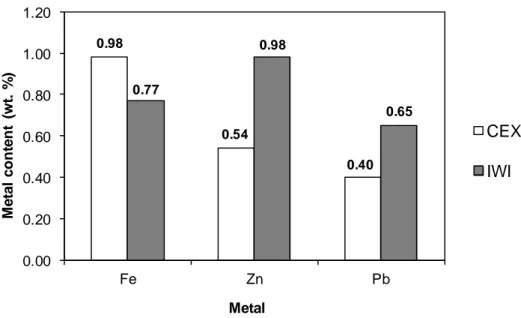
Figure 2 reports the ICP-AES analysis results of the metal contents of the sorbents. For iron and zinc, their theoretical contents were 1 wt.%. On the other hand, the theoretical content of lead was 0.7 wt.%. As expected, IWI method was effective for the deposition of all three metals. The metal contents obtained by ICP-AES analysis were close to the theoretical values. In fact, the only metal loss during this deposition method might be due to metal deposition on the flask wall. For the deposition of iron using CEX method, high deposition level was also observed. When CaP was added into the iron(III) nitrate solution for cationic exchange, the pH increased immediately to about 6. In these conditions, iron(III) could be exchanged with Ca(II),[31] and could be also precipitated on the surface of CaP particles. On the other hand, CEX method allowed only the partial deposition of lead(II) and zinc(II). This could be due to the low specific surface area of the commercial CaP used in this work, which was 7 m2/g.
Figure 2
All metal-doped CaP samples were characterized by XRD method, after calcination under air atmosphere at 400-500 °C for 2 h. No diffraction of the metals-based products (iron, lead, zinc) was observed, which can be explained by their low contents (less than 1 wt.%) and/or their high dispersion or amorphous form (XRD results not shown). All these samples show similar patterns compared to the initial CaP support. So the metal deposition by CEX or IWI methods, followed by calcination step did not change the apatitic crystalline structure of the initial support.
Figure 3
In order to identify the presence of metals on the surface of CaP support, SEM and TEM analyses were performed. Figure 3 illustrates SEM images of different solids obtained by CEX and IWI methods. Both lead-doped CaP solids (CEX-Pb and IWI-Pb) and zinc-doped CaP solid by IWI (IWI-Zn) showed lead and zinc based particles at micrometric scale. These particles had higher contrast, so higher brightness, compared to other elements present on CaP surface. In fact, IWI method is expected to deposit metal particles on the surface of the support. On the other hand, the formation of lead-based particle in CEX-Pb sample might be due to the agglomeration of lead during the thermal treatment.
Both iron-doped CaP solids (CEX-Fe and IWI-Fe) and zinc-doped CaP solid by CEX method did not show visible metals particles at micrometric scale. This could correspond to a high dispersion of these metals on the surface of CaP support and their thermal stability during the calcination under air atmosphere. To confirm it, TEM analysis of iron-doped CaP by IWI method was performed (Figure 4). The distribution of all elements present on this solid including P, O, Ca, Fe was also recorded. By contrast difference, TEM image shows the formation of iron clusters at nano-scale which had higher contrast than other elements of the CaP support (top, left-hand-side). By EDS analysis using SDD detector, P, O and Ca were homogeneously distributed on the surface of the particles. Iron could also be identified and it did not cover the entire surface of the support. The superposition of phosphorus, oxygen and iron demonstrates that iron was deposited on the surface of the CaP support (bottom, right-hand-side).
Figure 4
3.2. Removal of H2S diluted in air
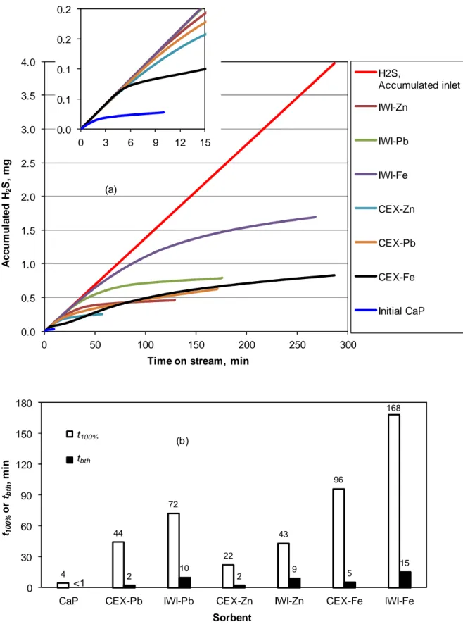
Figure 5 shows the results obtained for the synthetic effluent containing 200 ppmv of H2S in dry air atmosphere. As mentioned previously, for each sorbent, H2S, Accumulated inlet
curve (Fig. 5 (a)) was superposed with the curve expressing the total quantity of H2S captured
by the sorbent within t100% period. The initial CaP support showed very low reactivity under
the experimental conditions used, with tbth and t100% equal to 4 and < 1 min, respectively. On
the other hand, doping with metals increased strongly the reactivity of the initial CaP, with tbth
and t100% varying in the range of 22-168 and 2-15 min, respectively. The comparison of tbth for
all metals-doped CaP reveals that, for each metal, the solids prepared by IWI method were systematically more active than those prepared by CEX method. This observation was also
similar for the comparison of t100% obtained with these sorbents. In fact, IWI led to the
formation of dispersed metal-oxide particles on the surface of CaP support, which could react with H2S molecules. On the other hand, CEX method theoretically led to the insertion of
metal cations into and inside the apatitic structure of CaP, which probably became inert and unavailable for the fixation of H2S, when not localized on the surface. Among the prepared
sorbents, CaP doped with iron by IWI (IWI-Fe) was the most active for H2S removal,
regarding both t100% and tbth (Figure 5). After 260 min of time-on-stream, this sorbent was
completely saturated and the sorption capacity could be calculated, which reached 3.9 mg of H2S per gram of IWI-Fe.
Figure 5
The comparison of t100% and tbth for each sorbent shows that, under the experimental
conditions used, there were big gaps between t100% and tbth for all the sorbents. This suggests
slow kinetics for the H2S-sorbent interaction under the experimental conditions used.
Increasing contact time by decreasing gas flow rate or by increasing sorbent volume may reduce these gaps between t100% and tbth.
From the results obtained in Figure 5, three sorbents prepared by IWI method were selected for testing with synthetic gas effluent containing lower H2S concentration. Their
reactivity was compared with a commercial activated carbon (L3S powder, from CECA, France) as reference. Figure 6 confirms that the initial CaP had low reactivity for the abatement of H2S with negligible t100%, even with lower H2S concentration of 50 ppmv. As
expected, doping with metals made the sorbents much more active, with t100% equal to 31, 67,
and 85 min for the sorbents doped with Zn, Fe, and Pb, respectively. The reactivity of the CaP doped with metals was comparable to that of this activated carbon. This last one showed t100%
of 67 min, which was equal to the value obtained with IWI-Fe. Contrary to the results obtained with synthetic air containing 200 ppmv of H2S, IWI-Pb was found to be the most
efficient sorbent for synthetic air containing 50 ppmv of H2S. Standard characterizations such
as SEM-EDS, XRD, FTIR, TG-DSC were performed with sorbents recovered after sorption tests. However, since the content of sulphur compounds was low in the used sorbents, these characterization techniques did not allow explaining this observation. Further analysis is needed in order to understand these results.
Figure 6
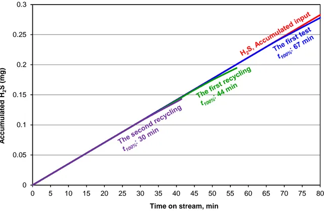
The saturated IWI-Fe sorbent recovered from the first test was thermally treated by calcination at 500 °C for 2 h. This temperature was chosen because it was the firing temperature for the preparation of the initial IWI-Fe sorbent. The objective was to release the sulfur species from the surface of the saturated sorbent. The regenerated sorbent was used again for hydrogen sulfide removal under the same experimental conditions (the 1st recycling). This regeneration procedure was repeated for the 2nd recycling. The results are presented in the Figure 7.
Figure 7
At this regeneration temperature (500 °C), IWI-Fe sorbent lost about one third of its reactivity at the first recycling. t100% decreased from 67 to 44 min. The observation was
similar at the second recycling wherein t100% decreased from 44 to 30 min. So, about one third
of available active sites (iron oxides) on the surface of HAP particles could not be reactivated at each recycling. This might be due to the formation of strong chemical bond between sulfur species and active sites, which could not be released by the calcination at 500 °C. This might be also due to the agglomeration of iron-based particles during the regeneration step at 500 °C, forming bigger iron-based particles and so reducing the dispersion of the active phase.
Figure 8
Reactivation study was also performed with the saturated activated carbon. After the first test with the fresh sorbent, the resulting saturated sorbent was regenerated by calcination at 400 °C under air atmosphere for 2 h. This regenerated sorbent was tested again under the same experimental conditions. The value of t100% of 49 min was obtained at the 1st recycling.
This indicates the similar reactivity of the reactivated carbon to IWI-Fe. The reactivity loss of the activated carbon might be due to the presence of irreversible interaction between sulfur-based species with active sites, or the partial destruction of active sites on the surface of the sorbent during calcination step.
4. Conclusions
Metals-doped apatitic calcium phosphates (HAP) were prepared by cationic exchange (CEX) and incipient wetness impregnation (IWI) methods. Metals-based particles could be observed at micrometric scale using SEM technique for lead- and zinc-doped HAP. On the other hand, iron-doped HAP contained particles at nanometric scale and were observed by TEM technique. For the removal of H2S diluted in air atmosphere, the initial HAP showed
reactivity of this initial HAP. For each metal, sorbents prepared by IWI method were found to be more reactive than those prepared by CEX method. IWI preparation led to the formation of dispersed metal particles which have available and reactive surfaces for H2S fixation. On the
other hand, CEX method led to the incorporation of metals in the CaP structure which makes the metal less available for the fixation of H2S. The sorbent containing only 0.77 wt.% of iron
and prepared by IWI method (IWI-Fe) had the similar reactivity compared to an activated carbon under the same experimental conditions. The reactivation of this sorbent (IWI-Fe) by calcination at 500 °C, after H2S removal test, allowed recovering two thirds of its reactivity.
This signifies the possible presence of irreversible interaction of sulfur-based species with the sorbent.
Future work will focus on the optimization of metal deposition for the formation of highly-dispersed metal particles at nanometric scale, and also on the influence of the contact time by changing the volume of sorbent’s bed. Other regeneration methods may be also investigated. The removal of H2S at high temperature, for example for the purification of hot
syngas generated from thermal gasification of biomass, seems to be particularly interesting because of high thermal stability of hydroxyapatite-based materials, as demonstrated previously.[30]
Acknowledgment
The authors gratefully acknowledge colleagues at RAPSODEE Center for technical help.
References
[1] Marzouk SAM, Al-Marzouqi MH, Teramoto M, Abdullatif N, Ismail ZM. Simultaneous removal of CO2 and H2S from pressurized CO2–H2S–CH4 gas mixture using hollow fiber
membrane contactors. Sep. Purif. Technol. 2012;86:88–97.
[2] Maghsoudi H, Soltanieh M. Simultaneous separation of H2S and CO2 from CH4 by a
high silica CHA-type zeolite membrane. J. Membrane Sci. 2014;470:159–165.
[3] Hao J, Rice PA, Stern SA. Upgrading low-quality natural gas with H2S- and CO2-selective
polymer membranes Part II. Process design, economics, and sensitivity study of membrane stages with recycle streams. J. Membrane Sci. 2008;320:108–122.
[4] Mondal P, Dang GS, Garg MO. Syngas production through gasification and cleanup for downstream applications - Recent developments. Fuel Process. Technol. 2011;92:1395– 1410.
[5] Castellani B, Rossi F, Filipponi M, Nicolini A. Hydrate-based removal of carbon dioxide and hydrogen sulphide from biogas mixtures: Experimental investigation and energy evaluations, Biomass Bioenergy 2014;70:330–338.
[6] Rezazadeh R, Rezvantalab S. Investigation of inlet gas streams effect on the modified Claus reaction furnace. Adv. Chem. Eng. Sci. 2013;3:6–14.
[7] Sublette KL. Oxidation of hydrogen sulfide by continuous cultures of Thiobacillus denitrificans. Biotechnol. Bioeng. 1987;XXIX:753–758.
[8] Oyarzun P, Arancibia F, Canales C, Aroca GE. Biofiltration of high concentration of hydrogen sulphide using Thiobacillus thioparus. Process Biochem. 2003;39:165–170. [9] Morales M, Arancibia J, Lemus M, Silva J, Gentina JC, Aroca G. Bio-oxidation of H2S by
Sulfolobus metallicus. Biotechnol. Lett. 2011;33:2141–2145.
[10] Omri I, Aouidi F, Bouallagui H, Godon JJ, Hamdi M. Performance study of biofilter developed to treat H2S from wastewater odour. Saudi J. Biol. Sci. 2013;20:169–176.
[11] Lebrero R, Gondim AC, Perez R, Garcia-Encina PA, Munoz R. Comparative assessment of a biofilter, a biotrickling filter and a hollow fiber membrane bioreactor for odor treatment in wastewater treatment plants. Wat. Res. 2014;49:339–350.
[12] Goifman A, Gun J, Gelman F, Ekeltchik I, Leva O, Donner J, Bornick H, Worch E. Catalytic oxidation of hydrogen sulfide by dioxygen on CoN4 type catalyst. Appl. Catal.
B: Environ. 2006;63:296–304.
[13] Bineesh KV, Kim DK, Kim MI, Park DW. Selective catalytic oxidation of H2S over
V2O5 supported on TiO2-pillared clay catalysts in the presence of water and ammonia.
Appl. Clay Sci. 2011;53:204–211.
[14] Duong-Viet C, Truong-Phuoc L, Tran-Thanh T, Nhut JM, Nguyen-Dinh L, Janowska I, Begin D, Pham-Huu C. Nitrogen-doped carbon nanotubes decorated silicon carbide as ametal-free catalyst for partial oxidation of H2S. Appl. Catal. A: Gen. 2014;482:397–406.
[15] Astarita G, Gioia F, Balzano C. Hydrogen sulphide absorption in aqueous monoethanolamine solutions. Chem. Eng. Sci. 1965;20:1101–1105.
[16] Kohl AL, Nielsen RB. Chapter 2 - alkanolamines for hydrogen sulfide and carbon dioxide removal. In: Gas Purification. 5th Ed. Gulf Professional Publishing; 1997. p. 40– 186.
[17] Haghtalab A, Izadi A. Simultaneous measurement solubility of carbon dioxide + hydrogensulfide into aqueous blends of alkanolamines at high pressure. Fluid Phase Equilibr. 2014;375:181–190.
[18] Song HS, Park MG, Ahn W, Lim SN, Yi KB, Croiset E, Chen Z, Name SC. Enhanced adsorption of hydrogen sulfide and regeneration ability on the composites of zinc oxide with reduced graphite oxide. Chem. Eng. J. 2014;253:264–273.
[19] Arespacochaga N, Valderrama C, Mesa C, Bouchy L, Cortina JL. Biogas deep clean-up based on adsorption technologies for solid oxide fuel cell applications. Chem. Eng. J. 2014;255:593–603.
[20] Florent M, Bandosz TJ. Effects of surface heterogeneity of cobalt oxyhydroxide/graphite oxide composites on reactive adsorption of hydrogen sulphide. Microporous Mesoporous Mater. 2015;204:8–14.
[21] Ri JN, Sub SH, Gyu PM, Jin KS, Jeong RH, Bok YK. Effect of reduced graphite oxide as substrate for zinc oxide to hydrogen sulfide adsorption. Clean Technol. 2013;19:300– 305.
[22] Pham Minh D, Nzihou A, Sharrock P. Carbonated hydroxyapatite starting from calcite and different orthophosphates under moderate hydrothermal conditions: Synthesis and surface reactivity in simulated body fluid. Mater. Res. Bull. 2014;60:292–299.
[23] Chaudhuri B, Mondal B, Modak DK, Pramanik K, Chaudhuri BK. Preparation and characterization of nanocrystalline hydroxyapatite from egg shell and K2HPO4 solution.
Mater. Lett. 2013;97:148–150.
[24] Figueiredo M, Fernando A, Martins G, Freitas J, Judas F, Figueiredo H. Effect of the calcination temperature on the composition and microstructure of hydroxyapatite derived from human and animal bone. Ceram. Int. 2010;36:2383–2393.
[25] Sasakin K, Goto T. Immobilization of Sr2+ on naturally derived hydroxyapatite by calcinations of different species of fish bones and influence of calcinations on ion-exchange efficiency. Ceram. Int. 2014;40:11649–11656.
[26] Sheha RR. Sorption behavior of Zn(II) ions on synthesized hydroxyapatites. J. Colloid Interf. Sci. 2007;310:18–26.
[27] Pham Minh D, Tran ND, Nzihou A, Sharrock P. Calcium phosphate based materials starting from calcium carbonate and orthophosphoric acid for the removal of lead(II) from an aqueous solution. Chem. Eng. J. 2014;243:280–288.
[28] Mobasherpour I, Salahi E, Pazouki M. Comparative of the removal of Pb2+, Cd2+ and Ni2+ by nano crystallite hydroxyapatite from aqueous solutions: adsorption isotherm study. Arab. J. Chem. 2012;5:439–446.
[29] Kramer E, Zilm M, Wei M. A comparative study of the sintering behavior of pure and iron-substituted hydroxyapatite. Bioceram. Dev. Appl. 2013 ;3:article N° 1000067 (9 pages).
[30] Galera Martínez M, Pham Minh D, Weiss-Hortala E, Nzihou A, Sharrock P. Compos. Interfaces 2013;20:647–660.
[31] Kousalya GN, Gandhi MR, Sundaram CS, Meenakshi S. Synthesis of nano-hydroxyapatite chitin/chitosan hybrid biocomposites for the removal of Fe(III). Carbohyd. Polym. 2010;82:594–599.
Table and figure captions
Figure 1. Experimental setup for H2S removal from gas phase.
Figure 2. Metals contents of the prepared sorbents obtained by ICP-AES analysis. Figure 3. SEM images of the prepared sorbents.
Figure 4. TEM image of IWI-Fe (top, left-hand-side) and the corresponding distribution of O, P, Ca and Fe.
Figure 5. Performance of the prepared sorbents for the removal of H2S (200 ppmv) diluted in
air. Experimental conditions: room temperature and pressure, 500 mg of sorbent, 50 mL/min of gas effluent. (a): “H2S, Accumulated inlet” curve: total quantity of H2S injected in the
reactor (or
m
Hinlet2S); other curves: total quantity of H2S captured by the sorbents (orsorbent S H
m
2 );
(b) Times for the complete removal of H2S (t100%) and breakthrough time (tbth).
Figure 6. Performance of the prepared sorbents and an activated carbon as reference for the removal of H2S (50 ppmv) diluted in air. Experimental conditions: room temperature and
pressure, 500 mg of sorbent, 50 mL/min of gas effluent. (a): “H2S, Accumulated inlet” curve:
total quantity of H2S injected in the reactor (or
inlet S H
m
2 ); other curves: total quantities of H2S
captured by the sorbents (or
m
Hsorbent2S ); (b): (b) Times for the complete removal of H2S (t100%).Figure 7. Regeneration study of the saturated IWI-Fe sorbent for the removal of H2S (50
ppmv) diluted in air. Regeneration procedure: calcination of saturated sorbent in air atmosphere at 500 °C. Experimental conditions: room temperature and pressure, 500 mg of sorbent, 50 mL/min of gas effluent. “H2S, Accumulated inlet” curve: total quantity of H2S
injected in the reactor (or
m
inletH2S); other curves: total quantities of H2S captured by thesorbents (or
m
Hsorbent2S ).Figure 8. Regeneration study of the saturated activated carbon sorbent for the removal of H2S
(50 ppmv) diluted in air. Regeneration procedure: calcination of saturated sorbent in air atmosphere at 500 °C. Experimental conditions: room temperature and pressure, 500 mg of sorbent, 50 mL/min of gas effluent. “H2S, Accumulated inlet” curve: total quantity of H2S
injected in the reactor (or
m
inletH2S); other curves: total quantities of H2S captured by theFigure 1. Experimental setup for H2S removal from gas phase.
H2S analyzer
H2S (50 or 200 ppmv) in dried air
Gas flow meter Sorbent bed
0.98 0.54 0.40 0.77 0.98 0.65 0.00 0.20 0.40 0.60 0.80 1.00 1.20 Fe Zn Pb M e ta l c o n te n t (w t. % ) CEX IWI Metal
Figure 3. SEM images of the prepared sorbents. IWI-Fe CEX-Fe IWI-Pb CEX-Pb IWI-Zn CEX-Zn
Figure 4. TEM image of IWI-Fe (top, left-hand-side) and the corresponding distribution of O, P, Ca and Fe.
0.0 0.5 1.0 1.5 2.0 2.5 3.0 3.5 4.0 0 50 100 150 200 250 300 A c c u m u la te d H 2 S , m g
Time on stream, min
H2S, Accumulated inlet IWI-Zn IWI-Pb IWI-Fe CEX-Zn CEX-Pb CEX-Fe Initial CaP (a) 0.0 0.1 0.1 0.2 0.2 0 3 6 9 12 15 4 44 72 22 43 96 168 2 10 2 9 5 15 0 30 60 90 120 150 180
CaP CEX-Pb IWI-Pb CEX-Zn IWI-Zn CEX-Fe IWI-Fe
t10 0 % o r tbth , m in Sorbent t B (b) t100% tbth <1
Figure 5. Performance of the prepared sorbents for the removal of H2S (200 ppmv) diluted in
air. Experimental conditions: room temperature and pressure, 500 mg of sorbent, 50 mL/min of gas effluent. (a): “H2S, Accumulated inlet” curve: total quantity of H2S injected in the
19
reactor (or
m
Hinlet2S); other curves: total quantity of H2S captured by the sorbents (orsorbent S H
m
2 );
0 0.05 0.1 0.15 0.2 0.25 0.3 0.35 0.4 0 10 20 30 40 50 60 70 80 90 100 110 A c c u m u la te d H 2 S , m g
Time on stream, min
H2S, Accumulated inlet Activated carbon IWI-Pb IWI-Fe IWI-Zn Initial CaP (a) 0 0.01 0.02 0.03 0.04 0 2 4 6 8 10 85 67 31 67 0 30 60 90 120 150 180
Initial CaP IWI-Pb IWI-Fe IWI-Zn Activated carbon
t10 0 % , m in Sorbent (b) <1
Figure 6. Performance of the prepared sorbents and an activated carbon as reference for the removal of H2S (50 ppmv) diluted in air. Experimental conditions: room temperature and
pressure, 500 mg of sorbent, 50 mL/min of gas effluent. (a): “H2S, Accumulated inlet” curve:
total quantity of H2S injected in the reactor (or
inlet S H
m
2 ); other curves: total quantities of H2S
0 0.05 0.1 0.15 0.2 0.25 0.3 0 5 10 15 20 25 30 35 40 45 50 55 60 65 70 75 80
Time on stream, min
A c c u m u la te d H 2 S ( m g )
Figure 7. Regeneration study of the saturated IWI-Fe sorbent for the removal of H2S (50
ppmv) diluted in air. Regeneration procedure: calcination of saturated sorbent in air atmosphere at 500 °C. Experimental conditions: room temperature and pressure, 500 mg of sorbent, 50 mL/min of gas effluent. “H2S, Accumulated inlet” curve: total quantity of H2S
injected in the reactor (or
m
inletH2S); other curves: total quantities of H2S captured by the0 0.05 0.1 0.15 0.2 0.25 0.3 0 5 10 15 20 25 30 35 40 45 50 55 60 65 70 75 80
Time on stream, min
A c c u m u la te d H 2 S ( m g )
Figure 8. Regeneration study of the saturated activated carbon sorbent for the removal of H2S
(50 ppmv) diluted in air. Regeneration procedure: calcination of saturated sorbent in air atmosphere at 500 °C. Experimental conditions: room temperature and pressure, 500 mg of sorbent, 50 mL/min of gas effluent. “H2S, Accumulated inlet” curve: total quantity of H2S
injected in the reactor (or