HAL Id: tel-00917964
https://tel.archives-ouvertes.fr/tel-00917964
Submitted on 12 Dec 2013HAL is a multi-disciplinary open access archive for the deposit and dissemination of sci-entific research documents, whether they are
pub-L’archive ouverte pluridisciplinaire HAL, est destinée au dépôt et à la diffusion de documents scientifiques de niveau recherche, publiés ou non,
protection
Afef Chammem
To cite this version:
Afef Chammem. Robust watermarking techniques for stereoscopic video protection. Other [cs.OH]. Institut National des Télécommunications, 2013. English. �NNT : 2013TELE0008�. �tel-00917964�
THESE DE DOCTORAT CONJOINT TELECOM SUDPARIS
et L’UNIVERSITE PIERRE ET MARIE CURIE
Thèse n°2013TELE0008
Spécialité : Informatique et Télécommunication
Ecole doctorale : Informatique, Télécommunications et Electronique de Paris
Méthodes de tatouage robuste
pour la protection de l'imagerie numérique 3D
Présentée par
Afef Chammem
Soutenu le 27 Mai 2013 à paris
Devant le jury composé de :
Prof. Touradj Ebrahimi Head of the MMSPG, EPFL Rapporteur
Prof. Laurent Lucas Head of the SIC Group, URCA Rapporteur
Prof. Patrick Gallinari Head of the LIP6, UPMC Président
Dr. Frédéric Dufaux CNRS Research Director, TelecomParisTech Examinateur
Prof. Faouzi Ghorbel Head of the CRISTAL Lab, ENSI Examinateur
Mme. Maryline Clare Head of the New Formats and New Coding Project,
Orange Labs Examinateur
Prof. Françoise Preteux Deputy Scientific Director, Mines ParisTech Directeur de thèse HDR. Mihai Mitrea Associate Professor, Telecom SudParis Co-Directeur de thèse
Table of Contents i
Table of Contents
Abstract ... 1
Chapter 1 Context ... 5
1.1. Stereoscopic content ... 7 1.1.1. Content proliferation ... 8 1.1.2. Device explosion ... 141.1.3. Potential protection techniques ... 17
1.2. Watermarking properties ... 18
1.2.1. Watermarking applicative panorama ... 18
1.2.2. Main watermarking constraints ... 20
1.2.3. From 2D to stereoscopic video watermarking ... 26
1.2.4. Theoretical framework for stereo watermarking ... 28
1.3. Thesis structure ... 30
Chapter 2 Objectives ... 31
2.1. Disparity maps computation ... 33
2.1.1. Basic concepts ... 33
2.1.2. Block matching disparity map computation in the literature ... 33
2.1.3. Conclusion ... 38
2.2. Watermarking embedding techniques... 38
2.2.1. Principles ... 38
2.2.2. State-of-the-art ... 39
2.2.3. Discussion ... 43
2.3. Conclusion and thesis objectives ... 48
Chapter 3 A new insertion domain: 3D Video-New Three Step Search ... 51
3.1. Method presentation ... 53
3.1.1. Principles ... 53
3.1.2. Pseudo-code and flowchart... 53
3.2. Experimental validation ... 58
3.2.1. Test bed ... 58
3.2.2. Horizontal and vertical displacements tendency ... 59
3.2.3. Visual investigation of the disparity maps... 60
3.2.4. Reconstructed image quality assessment ... 62
3.2.5. Computational cost ... 67
3.3. Discussion ... 70
Chapter 4 A reliable watermarking technique: Fast-IProtect ... 71
4.1. IProtect: hybrid embedding technique ... 73
4.1.1. IProtect embedding scheme ... 73
4.1.2. IProtect detection ... 78
4.2. Towards Fast-IProtect ... 78
4.2.1. Statistical models for watermarking attacks ... 80
4.2.2. Monte Carlo simulation for watermarking attacks ... 83
4.2.3. Experimental validation ... 86
4.3. Conclusion ... 87
Chapter 5 Stereoscopic watermarking benchmark ... 89
5.1. Embedding procedure ... 92 5.2. Embedding domains ... 94 5.3. Transparency evaluation ... 96 5.3.1. Subjective protocol ... 96 5.3.2. Objective assessment ... 104 5.4. Robustness evaluation ... 107 5.5. Computational cost ... 110 5.5.1. Processing time ... 110 5.5.2. Algorithmic complexity ... 110 5.6. Discussion ... 111
Chapter 6 Conclusion and future work ... 113
6.1. Conclusion ... 115
6.2. Future work ... 116
Appendix ... 117
A.1 Processed corpora ... 119
A.2 The considered embedding techniques ... 124
A.3 Transparency evaluation... 126
A.4 Robustness evaluation ... 132
References ... 135
List of acronyms ... 143
List of figures
iii
List of figures
Figure 1.1 Binocular human vision vs. stereoscopic content acquisition. ... 7Figure 1.2 Stereoscopic content display. ... 8
Figure 1.3 Content market value in the stereo 3D technology segment. ... 9
Figure 1.4 Timeline of 3D movies releases [Kun11]. ... 10
Figure 1.5 Overall TV and 3D TV sales 2009-2014 [Kin11]. ... 12
Figure 1.6 3D TV content need [Teu10]. ... 12
Figure 1.7 3D TV channel in the world [Teu10] [Kun11]. ... 13
Figure 1.8 Professional technologies for 3D TV [3DF13]... 14
Figure 1.9 Digital personal stereo vision systems [Koc10]. ... 15
Figure 1.10 Global 3D-enabled devices sales forecast from 2010 to 2014. ... 15
Figure 1.11 Samples of passive and active glasses for 3D viewer technologies [Kaw02] [Kun11]. ... 16
Figure 1.12 Lenticular lens and parallax barrier for autostereoscopic displays [Dod05]. ... 17
Figure 1.13 Samples of autostereoscopic displays [Kun11]. ... 17
Figure 1.14 The watermarking workflow. ... 19
Figure 1.15 “Big Buck Bunny” [Ble08], original frame with samples of its attacked versions. ... 24
Figure 1.16 Test image with samples of its corresponding attacked versions. ... 25
Figure 1.17 Watermarking as a noisy channel. ... 29
Figure 1.18 The theoretical model for stereo noisy channel. ... 29
Figure 2.1 Stereo matching. ... 33
Figure 2.2 Block searching strategies: (a) ES, (b) NTSS, and (c) FS –MPEG. ... 35
Figure 2.3. Synoptic representation of the state-of-the-art studies. ... 37
Figure 2.4 The watermarking embedder scheme. ... 39
Figure 2.5 Synoptic overview of the state of the art of the stereoscopic watermarking approaches. ... 40
Figure 2.6 Synoptic representation of the state-of-the-art studies. ... 45
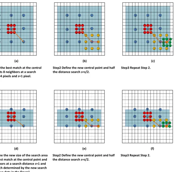
Figure 3.1 Block searching strategies: (a) NTSS, and (b) 3DV-NTSS. ... 53
Figure 3.2 The 3DV-NTSS algorithm flowchart. ... 56
Figure 3.3 The main three steps of the 3DV-NTSS algorithm. ... 57
Figure 3.4 Left and right views sampled from the 3DLive corpus. ... 58
Figure 3.5 Left and right views sampled from the MPEG corpus. ... 58
Figure 3.6 Search area weights variation ( and ) for 3DLive and MPEG corpora. ... 59
Figure 3.8 NTSS (a), FS-MPEG (b), and 3DV-NTSS (c) disparity maps. ... 61
Figure 3.9 NTSS (a), FS-MPEG (b), and 3DV-NTSS (c) disparity maps. ... 61
Figure 3.10 NTSS (a), FS-MPEG (b), and 3DV-NTSS (c) disparity maps. ... 62
Figure 3.11 Objective evaluation of the reconstructed image quality. ... 66
Figure 4.1 The watermarking method synopsis. ... 73
Figure 4.2 Treillis representation. Each row corresponds to one of the K states. ... 74
Figure 4.3 The selected sub-bands. ... 75
Figure 4.4 The embedded ARTEMIS logo... 75
Figure 4.5 The IProtect embedding algorithm synopsis. ... 77
Figure 4.6 IProtect time processing... 79
Figure 4.7 The five steps undergone when applying an attack procedure. ... 79
Figure 4.8 Fast-IProtect embedding algorithm synopsis. ... 80
Figure 4.9 The Monte Carlo attack simulation algorithm flowchart. ... 85
Figure 4.10 The quality of the Monte Carlo generators for the StirMark attack. ... 86
Figure 4.11 The attack procedure during the embedding process... 87
Figure 4.12 Time processing for different watermarking operations. ... 87
Figure 5.1 The watermarking assessment procedure. ... 91
Figure 5.2 View-based watermarking scheme. ... 95
Figure 5.3 Disparity-based watermarking scheme. ... 96
Figure 5.4 Presentation structure of the assessment session. ... 99
Figure 5.5 Side-by-side spread spectrum watermarked samples. ... 99
Figure 5.6 Side-by-side 2-QIM watermarked samples. ... 100
Figure 5.7 Side-by-side 5-QIM watermarked samples. ... 101
Figure 5.8 Side-by-side Fast-IProtect watermarked samples. ... 101
Figure 5.9 Subjective evaluations for image quality, depth perception and visual comfort. ... 104
Figure 5.10 Objective evaluation of the watermarked content visual quality... 106
Figure 5.11 Watermark robustness against five different attacks. ... 108
Figure 5.12. Watermarking chain computational cost. ... 110
Figure A.1.1 Left and right views sampled from the 3DLive corpus. ... 119
Figure A.1.2 Left and right views sampled from the MPEG corpus. ... 120
List of tables
v
List of tables
Table 1.1 The highest-grossing 3D films: Costs vs. incomes (in USD million). ... 11Table 1.2 Data payload requirements for some examples of watermarking applications. ... 26
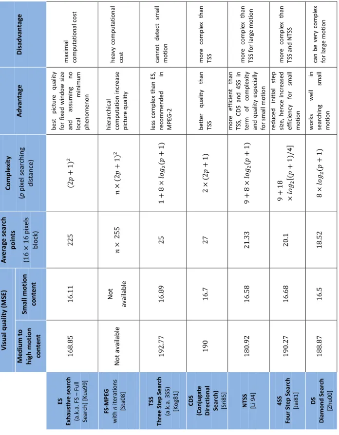
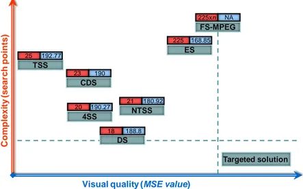
Table 2.1 Performance evaluation between the state of the art algorithms. ... 36
Table 2.2 A comparative view on the state of the art of stereoscopic image/video watermarking methods. ... 46
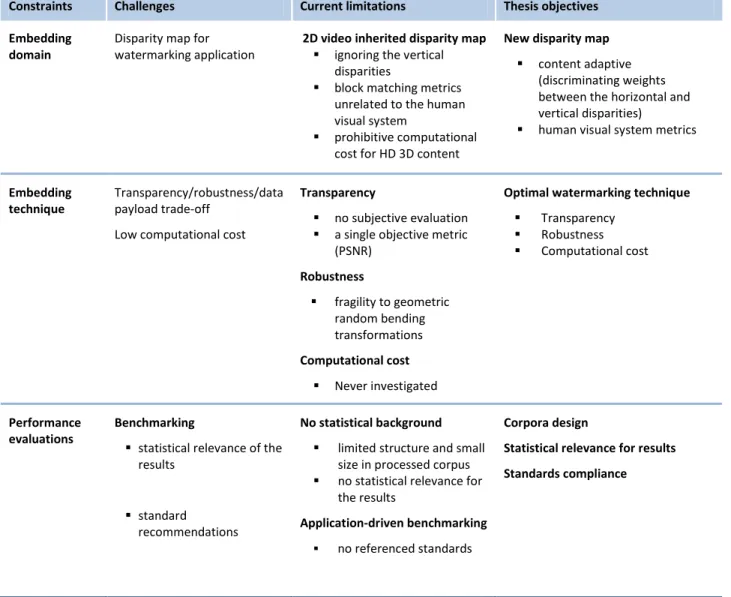
Table 2.3 The thesis main challenges, the underlying current limitations and the thesis objectives. ... 49
Table 3.1 Reconstructed image visual quality, expressed by PSNR, IF, NCC, SC and SSIM. ... 64
Table 3.2 95% error limits in reconstructed image quality assessment. ... 65
Table 3.3 Computational cost expressed in number of search points per 16x16 block. ... 68
Table 3.4 Gain factor on computational cost 3DV-NTSS vs. NTSS and 3DV-NTSS vs. FS-MPEG. ... 69
Table 4.1 Attacks statistical models in the (9,7) hierarchy. ... 82
Table 5.1 The considered insertion methods and their main parameters. ... 93
Table 5.2 General viewing conditions for subjective assessments at the ARTEMIS laboratory environment. ... 97
Table 5.3 Preferred Viewing Distance-PVD for moving image. ... 98
Table 5.4 A sample of a transparency: subjective evaluation sheet. ... 98
Table 5.5 Computational complexity of the watermarking modules involved in Fast-IProtect/3DV-NTSS... 111
Table A.3.1 The considered attacks and their main parameters. ... 127
Table A.3.2 The Mean Opinion Score values for a valid number of 25 subjects. ... 128
Table A.3.3 95% error of the MOS for a valid number of 25 subjects. ... 129
Table A.3.4 Watermarking transparency: 3DV-NTSS vs. NTSS vs. FS-MPEG, see Figure 5.10. ... 130
Abstract
1
Context
Coined in the mid‘ 50s for audio signals, the stereoscopic world is nowadays the challenge in image/video processing. On the one hand, medical diagnosis, fault detection in manufactory industry, army, arts all of them consider multi-view imaging as a key enabler for professional added value services. On the other hand, the worldwide success of movie releases (Avatar, Alice in Wonderland) and the deployment of 3D TV chains made the non-professional user aware about a new type of multimedia entertainment experience.
This explosion in stereoscopic video distribution increases the concerns over its copyright protection. Watermarking can be considered as the most flexible property right protection technology, since it potentially supports all the requirements set by real life applications without imposing any constraints for a legitimate user. Actually, instead of restricting the media distribution, watermarking provides means for tracking the source of the illegitimate usage.
Watermarking and its properties (transparency, robustness and data payload), from the embedding to the detection.
Applicative constraints
The watermarking applicative issue is to reach the trade-off between the properties of transparency, robustness and data payload. The transparency refers to the imperceptibility of the embedded additional information in the watermarked media. The robustness is the ability of detecting the watermark after applying some mundane or malicious attacks on the marked document (spatial filtering, lossy compression, recording, etc). The data payload represents the quantity of information that is inserted into the host document. In a real time context, the embedding and detecting modules must not slow down the production chain.
A specific study on the optimal (with respect to the above-mentioned properties) insertion domain is also required. While the capturing and displaying of the 3D content are solely based on the two left/right views, some alternative representations, like the disparity maps should also be considered during transmission/storage.
In order to pave the way from methodological development towards real life applications, the watermarking benchmarking should be application independent, reinforced by statistical relevance and fostered by standard recommendations.
Scientific and technical challenges
For 2D video watermarking applications, several classes of insertion techniques already proved their efficiency. For instance, SS (Spread Spectrum) techniques are generally connected to excellent transparency properties while ensuring good robustness for a quite small size of the mark. Conversely, SI (Side Information) techniques result in large sizes of the inserted marks, while decreasing the transparency/robustness properties. These two directions have been also extended for stereoscopic watermarking system. However, they still lack in achieving good transparency, they deal only with a restricted class of attacks and fail in embedding the required amount of data payload. Moreover, the transparency evaluation was solely guided by the PSNR values; no other objective transparency metrics or subjective evaluation protocols have been deployed. Consequently, specifying a watermarking method able to reach this three-folded trade-off is still an open issue. Such a study should also be accompanied by an evaluation of the computational cost.
Nowadays, stereoscopic video watermarking studies let the insertion domain selection to the experimenter’s choice rather than identifying it by objective studies. This way, the disparity maps are directly inherited from 2D video and simply neglect the stereoscopic video peculiarities. For such a content, the disparities between the left and the right views are predominant on the horizontal direction (where the very depth information is conveyed) while the vertical disparities, although non-zero, are mainly connected to the video shooting errors. Moreover, in the block matching stage, basic visual quality metrics like mean squared error – MSE or sum of absolute differences - SAD are considered. As such metrics are unrelated to the human visual system, the obtained results are sub-optimal from a quality of experience perspective. Consequently, specifying a disparity map, jointly exploiting the horizontal/vertical peculiarities of the stereoscopic content and a visual quality metric related to the HVS remains a challenging research topic.
Concerning the experimental validation, the processed data sets are restricted in their content heterogeneity and their size. Consequently, constructing a large and representative corpus to ensure statistical relevance for the results and performing the evaluation protocol according to some referenced standards are still desiderata.
Methodological contributions and achievements
The present thesis tackles the three above-mentioned challenges.First, by reconsidering some 2D video inherited approaches and by adapting them to the stereoscopic video content and to the human visual system peculiarities, a new disparity map (3D video-New Three Step Search - 3DV-NTSS) is designed. The inner relation between the left and the right views is modeled by some weights discriminating between the horizontal and vertical disparities. The block matching operation is achieved by considering a visual related measure, namely the normalized cross correlation -NCC. The performances of the 3DV-NTSS were evaluated in terms of visual quality of the reconstructed
Abstract
3 Second, a comparative study on the main classes of 2D inherited watermarking methods and on their related optimal stereoscopic insertion domains is carried out. Four insertion methods are considered; they belong to the SS, SI (binary QIM and -symbols QIM) and hybrid (Fast-IProtect) families. The fast-IProtect establishes synergies between SS and SI in order to achieve the transparency/robustness/data payload trade-off and relays on Monte Carlo generators, following the attack theoretical models, in order to meet time constraints. Each of these four methods is successively applied on the left view of the video sequences as well as on three disparity maps, computed according to the NTSS, FS-MPEG and 3DV-NTSS disparity map algorithms. The experiments brought to light that the Fast-IProtect performed in the new disparity map domain (3DV-NTSS) would be generic enough so as to serve a large variety of applications:
it ensures the imperceptibility according to subjective tests preformed based on three different criteria: image quality, depth perception and visual comfort;
it offers PSNR> dB and IF, NCC; SC and SSIM values larger than 1;
it ensures robustness expressed by a BER lower than after filtering and JPEG compression and lower than after the geometric random bending attacks;
it features a non-prohibitive computational cost (e.g. insertion time lower than the frame rate in video, Tinsertion= ms, obtained on a Core2 PC, [email protected], RAM 2 Go).
Finally, concerning the performance evaluation, all the quantitative results are obtained by processing two corpora (3DLive and MPEG) of stereoscopic visual content, organized according to three general criteria: significance, acceptability and exploitability. Each of these two corpora combines indoor/outdoor, unstable and arbitrary lighting, still and high motion scenes. The 3DLive corpus sums up about hours of HD 3D TV content captured by French professionals. The MPEG 3D video reference corpus is composed of minutes of video sequences provided by both academic/industry and encoded at different resolutions (from to pixels).
The statistical relevance of the results is given by the confidence limits computed for all the values reported in our study (for both transparency and robustness), and by their underlying the relative errors which were lower than .
Two standards have been considered in our study. The transparency of the watermarked content is subjectively assessed according to the ITU-R BT , and BT recommendations. The robustness and data payload were considered so as to comply with the Digital Cinema Initiatives (DCI) prescriptions.
1
Ideal transparency is given by , image fidelity , normalized cross correlation , structural content and structural similarity .
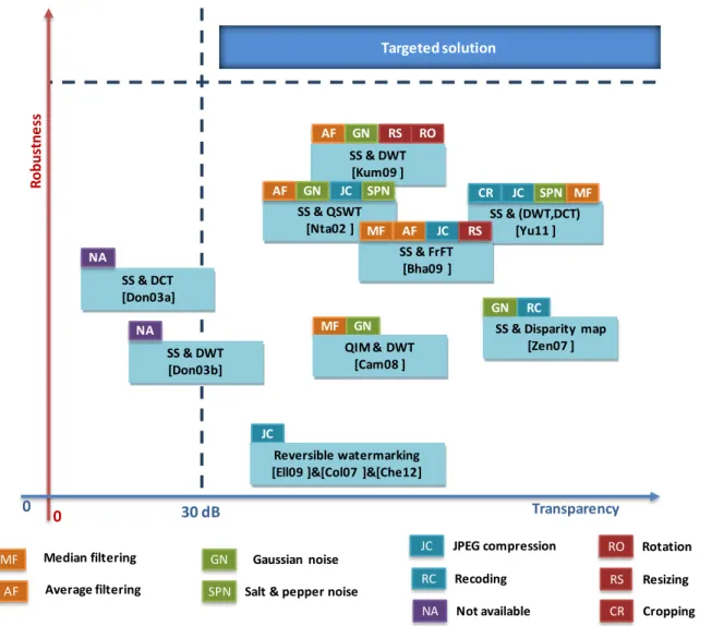
Stereoscopic video watermarking: constraints, challenges, current limitations and thesis contributions.
Constraints Challenges Current limitations Thesis contributions
Embedding domain
Disparity map for watermarking application
2D video inherited disparity map
ignoring the vertical disparities
block matching metrics unrelated to the human visual system
prohibitive
computational cost for HD 3D content
New disparity map: 3DV-NTSS Principle
content adaptive (discriminating weights between the horizontal and vertical disparities)
human visual system metrics
Experimental validation
reconstructed image quality: gains of 2dB in PSNR and 0.10 in SSIM
computational cost: reduction by factor between 1.3 and 13
Embedding technique
Transparency/robustness /data payload trade-off
Low computational cost
Transparency
no subjective evaluation a single objective metric
(PSNR) Robustness fragility to geometric random bending transformations Computational cost Never investigated Fast-IProtect/3DV-NTSS watermarking Principle
Joint SS and SI watermarking Monte Carlo generators following the
attacks theoretical models
Transparency
no perceptual difference between the
original and watermarked sequences
difference and correlation based
measures: PSNR> 35dB and IF, NCC, SC and SSIM >0.95
Robustness
filtering and compression: BER<0.05
geometric random bending
transformations: BER<0.1
Computational cost
real time compatibility
Performance evaluations Benchmarking statistical relevance of the results standard recommendations No statistical background
limited structure and small size in processed corpus
no statistical relevance for the results
Application-driven benchmarking
no referenced standards
Corpora (significance, acceptability and
exploitability)
3Dlive, HD full encoded (2h11min24sec) MPEG, multiple resolutions and frame
rates (17min29sec)
Statistical relevance for all results
95% confidence limit with relative errors
Transparency
ITU-R recommendations (ITU-R BT
Abstract
This Chapter browses the thesis basis, from the advent of the video stereoscopic content to the watermarking potentiality to solve issues related to copyright protection. Finally, the thesis structure is identified by facing the stereoscopic video protection to the main watermarking properties.
Chapter 1: Context
7
1.1. Stereoscopic content
From the etymological point of view, the word stereopsis derives from the Greek words “stereo” meaning solid and “opsis” meaning appearance or sight [May81] [Rog82] [Pog84].
Under the image processing framework, the word stereoscopy encompasses the research and technological efforts related to the design and deployment of tools able to create/enhance the illusion of depth in image [Rog82] [Pog84].
From the anatomic point of view, the human brain calculates the depth in a visual scene mainly by processing the information brought by the images seen by the left and the right eyes. These left/right images are slightly different because the eyes have biologically different emplacements2, Figure 1.1 a. Consequently, the straightforward way of achieving stereoscopic digital imaging is to emulate the Human Visual System (HSV) by setting-up (under controlled geometric positions), two traditional 2D cameras, see Figure 1.1.b. Such a representation is commonly referred to as two-view stereo [Sch02] [Fra02].
(a) Binocular human visual system. (b) Stereoscopic system emulating human
visual system.
(c) Depth image based rendering.
Figure 1.1 Binocular human vision vs. stereoscopic content acquisition.
An alternative way of achieving depth in images is by exploiting the Depth Image Based Rendering (DIBR) principle [Feh03] [Fra11]: this time, the stereoscopic left/right views are created from an image captured with a traditional 2D camera centered in-between the eyes and from the depth estimated by the camera itself, see Figure 1.1 c.
2
The difference between the left and right eye images is called binocular disparity. Original object
Left view Right view
Original object
Left view Right view
Original object
Regardless of the capturing method, the stereoscopic video content is displayed in the same way, see Figure 1.2.
The viewer brain is provided with two different images, representing two perspectives of the same object. For basic stereoscopic imaging, these two images are the left/right views captured by two cameras. For DIBR, the two images are rendered from the central view and the depth information3. An additional mechanism, a filter (as illustrated in Figure 1.2) should be considered in order to merge (for visual perception purposes) these images. This filter can be on the user side (i.e. a headgear or glasses) or on the screen side (i.e. a lenticular lens or a parallax barrier). A discussion in this respect is presented in Chapter 1.1.2 (3D displays).
(a) basic stereoscopic imaging. (b) DIBR.
Figure 1.2 Stereoscopic content display.
1.1.1.
Content proliferation
To the best of our knowledge, the first experiments devoted to the creation of stereoscopic images were reported at the beginning of the 19th century [Wad87] [Lat38]. They considered a stereoscope which is an optical device with two eyepieces, through which two slightly different images of the same scene are presented individually to each eye, thus giving the illusion of depth.
Today, the stereoscopic content is preponderantly digital and its market is forecast to reach more than 4 billion USD in 2014, see Figure 1.3, [Ped13].
Screen
Left view Right view
Filter
Screen Central view
Filter Depth map
Chapter 1: Context
9
Figure 1.3 Content market value in the stereo 3D technology segment. (from 2010 to 2014 in million U.S. dollars [Ped13]).
3D Cinema
From the final user’s point of view, the 3D cinema with its 120 years history, represents the most appealing instantiation of the stereoscopic imaging [Kun11], Figure 1.4.
Experiments and first patent
The first important stereoscopic era of motion pictures began in the late 1890s when British film pioneer William Friese-Greene filed a patent for a 3D movie process. In his patent, two films were projected side by side on a screen. The viewer looked through a stereoscope to converge the two images. Later on, some movie excerpts were played and presented for tests to the audience.
Early stereoscopic production
In 1922, the American silent movie “The power of love”, produced by Harry K. Fairall, was widely reported as the first full length 3D movie presented in anaglyph (see Chapter 1.1.2, 3D displays). The late 1920s to early 1930s witnessed no interest in stereoscopic pictures. The 1940s saw a mini-boom for 3D releases especially in the USSR. The first talking 3D movie was Alexander Andreyevsky's Soyuzdet film production “Robinson Crusoe” which was shown at the Vostok cinema in 1947. A few other 3D films followed to the end of the 1940s.
The golden era (1952–1955)
The early 1950s were a bad time for the movie industry. The popularity of television kept people out of the theaters. The movie industry used 3D as a way of increasing the audience, a strategy which made 3D enter its booming years. Hence the "golden era" of 3D began in 1952 with the release of the first color stereoscopic film, Bwana Devil, produced, written and directed by Arch Oboler. Starting from this moment, most 3D movies used the polarizing process (see Chapter 1.1.2, 3D displays).
0 1000 2000 3000 4000 5000 2010 2011 2012 2013 2014 M ar ke t val u e in m ill io n US D
Rebirth of 3D (1970–1986)
The huge number of movie releases during the golden era allowed the audience to experience head-aches and 3D gained a bad reputation. Consequently, the audience dropped down and 3D entered a hibernation period. The late 1970s witnessed a revival of the 3D with the design of new stereovision caption and projection technologies.
In the mid-1980s, IMAX theaters provided a perfect environment for 3D movie projection. They emphasized mathematical correctness of the 3D rendering and thus largely eliminated the eye fatigue and pain of previous 3D presentations. Unfortunately, at the end of the 1980s, the 3D movie production collapsed.
Figure 1.4 Timeline of 3D movies releases [Kun11]. Second boom in 3D movies (1993-present)
From 1993, numerous films were produced announcing the comeback of 3D. In the early 2000s, first full-length 3D IMAX feature movies were released using the new technologies (Real D 3D, Dolby 3D, XpanD 3D, MasterImage 3D, and IMAX 3D)
In 2009, Avatar was one of the most influential film with about 285 millions viewers worldwide. Three major 3D releases followed in 2010: Alice in Wonderland hitting US theaters on March 5, How to Train
Your Dragon on March 26 and Clash of the Titans on April 2.
Today, 3D movies are extremely expensive to make, and only big-budget studio production can afford them, see Table 1.1. Comparing to the highest-grossing 2D movies, 3D movie production is holding the record with acknowledged costs larger than a nominal value of USD 150 million and going usually over USD 300 million. The white paper [Saf11] looked at the actual costs of a 2D and 3D production of the same movie and studied the cost increase of a 3D film over its 2D counterpart under various trade-offs
0 5 10 15 20 25 30 35 40 45 50 1903 1913 1923 1933 1943 1953 1963 1973 1983 1993 2003 2013 M ov ie r e le as e s First patent and tests A second boom in 3D movies The golden era
Early stereoscopic
prodcution
Chapter 1: Context
11 average increase cost of 18%. The vast majority of cost increases comes from the increase in 3D cameras rental costs and from the addition of staff members.
3D movies are not only on the top of cost production but also on the top of the highest grossing films, see Table 1.1. For instance, with a worldwide box-office gross of about USD 2.8 billion, Avatar is often proclaimed to be the highest-grossing film ever. The Transformer comes in the second place with about USD billion. Alice in wonderland gross reached USD 1.024 billion. The incomes above include revenue coming from theatrical exhibition, home video, television broadcast rights and merchandising.
The releases in multiple formats impacts the number of people purchasing movie tickets. Almost two-thirds of the tickets sold were for 3D showings with an average price of USD 10.
Table 1.1 The highest-grossing 3D films: Costs vs. incomes (in USD million).
Movie Avatar Alice in
Wonderland
Toy Story 3 Transformers: Dark of the Moon Year 2009 2010 2010 2011 Cost 280 236 200 195 Worldwide gross 2782 1024 1063 1123
3D Television
The awareness about the 3D movie experience is currently extended and promoted from theater to homes.
The report, "Global 3D-Enabled Device Sales Forecast" [Kin11] predicts that 34% of US homes will own a 3D-ready TV by 2014. In Europe, 3DTV ownership will grow a bit faster, with 42% of homes owning a 3DTV by 2014. Moreover, the study affirms that the TV market is proliferating and most major TV producers are expected to launch new 3D TV technologies. Consequently, 3D TV is expected to surpass 59 million units in 2013 (hence to account 23% of the overall market) and to exceed 83 million units in 2014 (hence to account about 31% of overall TV market), see Figure 1.5.
According to the report made by the market intelligence firm NPD DisplaySearch [Whe12], the 3D television industry is forecast to almost quadruple over the next seven years. In this respect, analysts predict that the tri-dimensional display market will see worldwide revenue growth from USD 13.2 billion/year to more than USD 67 billion/year by 2019. In the same line, the demand for 3D TV products is expected to grow to 180 million units per year by 2019 [Whe12].
Figure 1.5 Overall TV and 3D TV sales 2009-2014 [Kin11].
3D television must not only face the issue of TV devices but also the need for high-quality content. Although we could not find financial estimation concerning the 3DTV content trends, the increasing number of 3D channels in the world (see Figure 1.7), along with the increasing number of viewers interested in such programs (see Figure 1.6) imposes it as a high added value market [Teu10].
Figure 1.6 3D TV content need [Teu10].
0 50 100 150 200 250 300 350 400 2009 2010 2011 2012 2013 2014 M ill io n u n its
3D TV market evolution
3D TV Total TV 0 500 1000 1500 2000 2500 3000 3500Hours of program for a thematic channel
Number of films for a movie channel
3D content needed 3D content available
Chapter 1: Context
13
1.1.2.
Device explosion
The content proliferation is supported by explosive effort in 3D devices manufacturing:
3D capturing devices
For side-by-side stereoscopic shooting, two synchronized cameras must be used. The distance between the center of the lenses of the two cameras is called the interaxial, and the cameras' convergence, is called the angulation. These two parameters can be modified according to the expected content peculiarities.
The two cameras must be correctly aligned, identically calibrated (i.e. brightness, color, etc…) and perfectly synchronized (frame-rate and scan-wise).
To hold and align the cameras, a 3D-rig is used (see Figure 1.8). The rigs can be of two main types: - the side-by-side rig, where the cameras are placed side by side (Figure 1.8.a). This kind of 3D-rig is mostly useful for large landscape shots since it allows large interaxials; however, it doesn’t allow small interaxials because of the physical size of the cameras.
- the mirror rig, also called the beamsplitter rig (Figure 1.8.b), where one camera films through a semi-transparent mirror, and the other films the reflection in the mirror. These rigs allow small and medium interaxials, useful for most shots, but not the very large interaxials (because the equipment would be too large and heavy).
Monoblock cameras have been designed as well, where the two cameras are presented in a fixed block and are perfectly aligned, which avoids cameras desynchronization (Figure 1.8.c).
(a) Side-by-side rigs (b) Semi transparent mirror rigs (c) Monoblock camera
Chapter 1: Context
15 A second category of 3D shooting devices is presented in Figure 1.9. These electronic devices are less expensive and are targeting the user-created stereoscopic picture/movie distribution.
(a) Mobile phones (b) Digital cameras (c) camcorders
Figure 1.9 Digital personal stereo vision systems [Koc10].
3D displays
Improvements in camera, post-production and projector technology lead to the increase of 3D production’s quality. Although these new technologies have high costs, film production companies are competing to release high quality 3D movies and to grant the audience a pleasant experience of 3D. Moreover the 3D devices ownership is growing steadily and will accelerate rapidly over the next three years, according to the latest research from Strategy Analytics [Kin11]. Global sales of 3D-enabled devices are expected to grow with 40% in 2013, to reach 555 million units and 900 million units in 2014, see Figure 1.10. This forecast includes 3D-ready TVs, 3D TV set-top boxes, 3D Blu-ray players, 3D media players, 3D phones and 3D fixed and portable games consoles.
Figure 1.10 Global 3D-enabled devices sales forecast from 2010 to 2014.
(source: Strategy Analytics, “connected home devices services”, March 2011). The portable devices include cameras, camcorders, media players and phones [Kin11].
From 1900 onward, the 3D movie releases and television broadcasts were based on two types of 3D displays [Kaw02]: stereoscopic 3D and auto-stereoscopic.
0 100 200 300 400 500 600 700 800 900 2010 2011 2012 2013 2014 M illi o n s u n its
3D devices evolution
3D portable devices 3D media players 3D games consol 3D desktop PCs ¬ebooks 3D BD players/ recorders 3D TV recievers 3D TV displaysFor the first category (stereoscopic 3D displays), the viewer needs to wear special glasses which separate the views of the stereoscopic image for the left and the right eye. These 3D glasses can be active or passive.
On the one hand, active glasses are controlled by a timing signal that allows to alternatively darken one eye glass, and then the other, in synchronization with the refresh rate of the screen. Hence presenting the image intended for the left eye while blocking the right eye's view, then presenting the right-eye image while blocking the left eye, and repeating the process at a high speed which gives the perception of a single 3D image. This technology generally uses liquid crystal shutter glasses, see Figure 1.11.a. On the other hand, passive glasses are polarization-based systems [Kaw02] and contain a pair of opposite polarizing filters; each of them passes light with similar polarization and blocks the opposite polarized light (Figure 1.11.b). The polarized glasses are associated with a display with polarized filters, providing each eye with the appropriate image.
The color anaglyph-based systems are a particular case of the passive glasses and use a color filter for each eye, typically red and cyan, Figure 1.11.c. The anaglyph 3D image contains two images encoded using the same color filter, thus ensuring that each image reaches only one eye.
(a) LCD shutter glasses (b) Polarized glasses (c) Anaglyph glasses
Figure 1.11 Samples of passive and active glasses for 3D viewer technologies [Kaw02] [Kun11].
For the second category (auto-stereoscopic), the viewer doesn’t need to use any headgear or glasses. This category called also glasses-free 3D includes lenticular lens, parallax barrier, holography and volumetric displays [Dod05] [Hal05] [Kun11], Figure 1.12.
The lenticular lens and the parallax barrier are devices placed in front of an image source, such as a projector or an LCD monitor, to allow it to discriminate between the content to be presented to the left/right eyes.
The lenticular lens is a layer of lenses, designed so that when viewed from slightly different angles, different images are magnified, Figure 1.12.a. However, the parallax barrier consists of a layer of material with a series of precision slits, allowing each eye to see a different set of pixels, therefore creating a sense of depth through the parallax, Figure 1.12.b. This technology is used in some auto-stereoscopic phones and video game consoles such as the Nintendo 3DS. Their major limitation lies in the so-called sweet-spot which represents the region where the viewer must be placed to perceive the 3D effect. This region can be very narrow depending on the technology, and if the viewer changes
Chapter 1: Context
17
(a) Lenticular lens (b) Parallax barrier
Figure 1.12 Lenticular lens and parallax barrier for autostereoscopic displays [Dod05].
Holography-based devices create a light field with both horizontal and vertical parallax across a large range of viewing angles. They use some optical phenomena (i.e interference, diffraction) and light intensity to reproduce 3D images from the original scene, see Figure 1.13.a.
Volumetric devices (e.g. multi-planar displays), have stacked up displaying planes, and as well as rotating panel displays. These technologies display points of light within a volume giving 3D depth to the objects, see Figure 1.13.b.
(a) Holography (b) Volumetric displays
Figure 1.13 Samples of autostereoscopic displays [Kun11].
1.1.3. Potential protection techniques
The proliferation of content production and the explosion of its devices turn the issues related to the stereoscopic content traceability and copyright protection into a hot research topic.
Digital Rights Management
The Digital Rights Management (DRM) refers to a set of policies that define the digital content owner rights and specify the appropriate content consumption and distribution modes. Thus, it enables the secure exchange of high-value content over the Internet or any electronic devices (i.e. DVD, mobile
Lenticular lens Right Left Right Left Pixels Parallax barrier Right Left Right Left Pixels
network, etc). Unfortunately, the restrictions imposed by DRM have made people uncomfortable when using digital medias [Sub06] [Har00].
Cryptography
Cryptography is a term derived from the Greek words cryptos, which means hiding or secret, and
graphei, which means writting. Cryptography is the most common method of protecting digital content,
and consists in encrypting the content with an encryption key that is later provided only for legitimate users for decryption. The content can be uploaded on the Internet without any risk of piracy as long as the key is not provided. Unfortunately, once the pirate has access to the decryption key after a legitimate purchase of the product, he/she is able to distribute illicit copies. Hence, cryptography is a good mean of data protection during its transmission, but once the content is decrypted, no further protection is ensured [Cox02].
Steganography
Steganography is also of Greek origin, derived from steganos, meaning covered or protected, and
graphei which means writing. It is the art of writing hidden messages in a way that no one but the sender
and the receiver know about the existence of the message. Hence, a secret message is encoded in a manner that its very existence is covered. The main goal of steganography is to communicate securely in a completely undetectable manner. The security of steganography systems relies on the security of the data encoding system. Once this later is known, the steganogrpahy system is defeated. Moreover, the hidden message can be easily removed after applying some common multimedia operations on the host-media content [Cox02].
Digital watermarking
Watermarking can be considered as the most flexible property right protection technology, since it potentially supports all the requirements set by real life applications without imposing any constraints for a legitimate user. This technology adds some information (a mark, i.e. copyright information) in the original content without altering its visual quality. Such a marked content can be further distributed/consumed by another user without any restriction. Still, the legitimate/illegitimate usage can be determined at any moment by detecting the mark. Actually, the watermarking protection mechanism, instead of restricting the media copy/distribution/consumption, provides means for tracking the source of the content illegitimate usage [Cox02] [Mit07].
1.2. Watermarking properties
A watermarking technique [Cox02] [Mit07] consists in imperceptibly (transparently) and persistently (robustly) associating some extra information (a watermark) with some original content. A synopsis of the watermarking process is presented in Figure 1.14.
Chapter 1: Context
19 documents, photos, audio, video, etc [Dig03]. Stereoscopic imaging comes with an extensive range of applications, such as 3D television, 3D video applications, robot vision, virtual machines, medical surgery and so on, which emphasize the importance of the watermarking solution.
Figure 1.14 The watermarking workflow.
Digital Right Management
Copyright protection is the main application of watermarking techniques aiming to prevent or deter unauthorized copying of digital media. Digital watermarks contain a set of copy control instructions, which tell the copy devices if copies are allowed, or not.
Forensics and piracy tracking
Forensic watermarking applications enhance the content owner's ability to detect and respond to the misuse of his/her assets. Digital watermarking is used not only to gather evidence for criminal acts, but
Original content Digital watermark Embedding process Watermarked content
The recovered watermark
Watermarked content releases in several formats
Mobile phone Video/image Television/cinema
100010100001001001000100001000010101001000000000000 1011110100110110100100010101101011100110001100111
Digital contents are
often cropped, resized, compressed and edited.
also to enforce contractual usage agreements between a content owner and the customers. It provides positive, irrefutable evidence of misuse for leaked content assets [Dig03].
Authentication and integrity
Digital watermarks are imperceptibly embedded into all forms of media content, be they individually or aggregately distributed/stored. The watermark can uniquely identify each specific item or instance of content and carry information about its consumption chain and intended destinations. Watermarks can be encrypted and secured so that only authorized reading devices can detect and access the data. Altering a watermark is virtually impossible and the carried data can immediately indicate if the content is genuine or a counterfeit [Sam09].
Broadcast and Internet monitoring
Over the last few years, the amount of content flowing through television/radio channels continues to grow exponentially. Watermarking techniques offer the best solution to automate the monitoring of digital content. The original content, which has been embedded conveys a unique identifier (owner, distributor, data/time information) allowing the content owners and distributors to track their media [Sam09].
Asset and content management
Watermarking techniques enable effective content identification by giving a unique digital identity to any type of media content and by embedding this identity as additional hidden information [Sam09]. The watermarks have to be imperceptible and to have minimal or no impact on the visual quality of the original content. Hence they can be used as a persistent tag, acting as keys into a digital asset management system (DAM). Tagged content can lead back to the original content stored in the DAM system; it can also be linked to metadata in the DAM, such as keywords, rights and permissions.
Filtering/classification
Digital watermarks offer new opportunities for content owners, advertisers and more generally marketers searching for new ways to engage consumers in richer media experiences. In fact, the embedded information enables the identification, classification and filtering of multimedia content. The watermarking systems are able to selectively filter potential inappropriate content (e.g. parental control).
1.2.2.
Main watermarking constraints
To assess the performances of a watermarking technique, the following main properties are generally considered: transparency, robustness, data payload, false positive rate and computational cost. According to the targeted application, different constraints are set on these properties.
Chapter 1: Context
21
1.2.2.1. Transparency
Transparency can be defined as the imperceptibility of the embedded additional information in the watermarked media. This may signify either that the user is not disturbed by the artefacts induced by the watermark in the host document or that the user cannot identify any difference between the marked and the unmarked document.
Subjective evaluation
In order to assess the impact of these artefacts from the human visual point of view, subjective protocol and objective quality measures can be considered.
The International Telecommunication Union (ITU) defined some recommendations to be followed for the subjective evaluation [BT98] [BT00] [BT02]. First, it states the required material for the test, such as the monitor and its calibration parameters and defines the environment conditions such as the testing room luminance in order to ensure the reproducibility of results. Second, the panel size is designed depending on the sensitivity and reliability of the test procedure adopted and upon the anticipated size of the effect sought. The minimum number of observers is fixed at 15. The observer’s visual acuity and color vision have to be tested according to Snellen chart and Ishihara test, respectively. Other tests are required for different types of content (i.e. fine stereopsis and dynamic stereopsis tests for stereoscopic content assessment).
The ITU-R BT.500-12 also describes methods for subjective quality assessment of the quality of television pictures. Among these, the research community considers the Double-Stimulus Continuous Quality-Scale (DSCQS), the Double-Stimulus Impairment Scale (DSIS) and the single Stimulus for Continuous Quality Evaluation (SSCQE).
Finally, rules for score computation and results analysis were defined.
Objective quality metrics
The visual quality of the watermarked content can also be objectively evaluated. The objective metric is a function that takes as input some video/image information (e.g. pixel intensity), calculates the distance to some reference information and outputs a value giving the distortion level. In our study we consider five objective metrics [Esk95] [Chi11] [Wan04], of two types, namely:
Pixel-based measures: the Peak Signal to Noise Ratio-PSNR and the Image Fidelity-IF;
Correlation based measures: the Normalized Cross Correlation-NCC, Structural Content-SC and
Structural SIMilarity- SSIM.
These values are individually computed at the frame level, and then averaged over all the frames in the video sequence.
Consider two frames, and ; then:
where and are the pixel intensity at location in and , respectively. are the
height and width of the frames while and are the corresponding mean values and standard deviations, and are parameters adjusting the relative importance of the three components [Wan04]. In order to simplify the expression, the study in [Wan04] suggests to consider . The luminance , the contrast and structure of the two frames and are defined by
where , et are small constants given by , and , is the dynamic range of pixel values, and .
1.2.2.2. Robustness
The robustness refers to the ability of detecting the watermark after applying some signal modifications operations and malicious attacks on the marked document, such as spatial filtering, lossy compression, recording, etc.
The watermarking techniques can be divided in three main classes according to their robustness level set by the targeted application: robust, fragile and semi-fragile watermarking [Lin00] [Bar01a] [Wol99]. Robust watermarking is designed to withstand attacks. The presence of the embedded watermark must be detected after common data manipulations and malicious transforms. Fragile watermarking is designed to detect any changes in the original content. Thus, it refers to the case where the inserted watermark is lost or altered as soon as the host content suffers modifications. This way, the watermark loss or alteration is taken as evidence that data has been tampered with. The watermark is said semi-fragile if it survives only a particular kind of manipulations (e.g. moderate compression or video format change) thus allowing that particular content modification to be identified.
The distortions a watermarked content can suffer can be classified in three classes: valumetric, temporal and geometric [Cox02].
The valumetric distortions include the additive noise, linear filtering, lossy compression and quantization. The additive noise can be added to the content when applying some usual processing or when
Chapter 1: Context
23 watermarking schemes. Finally, a good watermarking system has to survive the quantization which generally occurs during a Discrete Cosine Transform (DCT) or Discrete Wavelet Transform (DWT) used for compression purposes.
The temporal distortions include delay and temporal scaling. This type of attacks often occurs during the conversions between different television standards, for example the frame-rate changes.
The geometric distortions include rotations, translations, spatial scaling, cropping and changes in aspect ratio.
All these types of distortions are considered as malicious attacks and can occur due to user manipulations. For images, such manipulations can be printing and scanning. However, for video content, geometric distortions commonly occur during format changes.
Attacks are very likely to appear during the stereoscopic content processing workflow and it is hard to design a watermarking system able to survive all types of distortions while preserving the watermarked content‘ s fidelity.
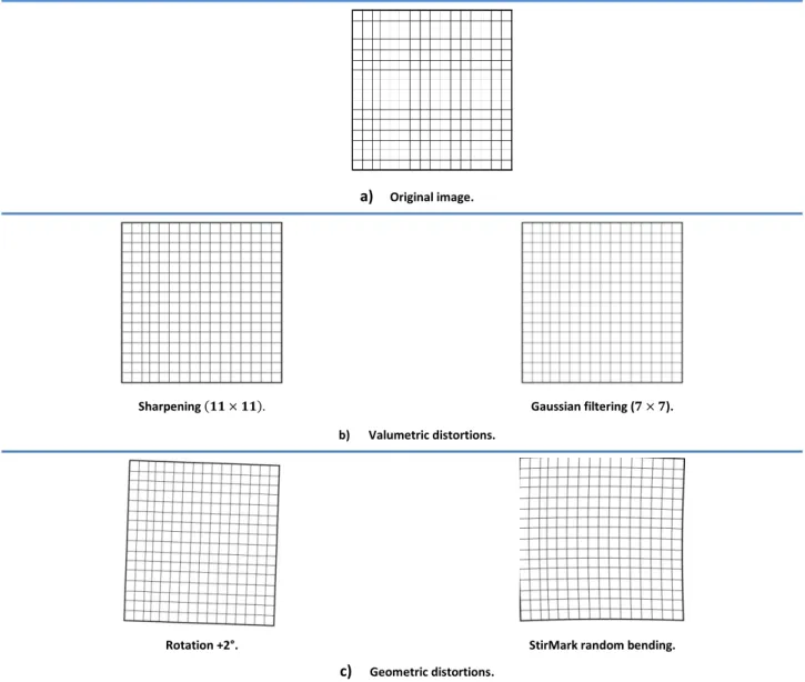
StirMark is a generic tool developed for robustness assessment of image watermarking algorithms [Pet98] [Pet00]. Among a large class of attacks, it also includes StirMark random bending, a simulator of the random errors induced when printing the image on a high quality printer and then scanning it with a low quality scanner. It also applies minor geometric distortions: the image is slightly stretched, sheared shifted and rotated by a random amount and the re-sampled by using Nyquist interpolation, see Figure 1.15.c (right) and Figure 1.16.c (right)4.
Figures 1.15 and 1.16 show some of the most common attack effects on one image taken from the corpus processed in the thesis, see Appendix A.1 and on a test image respectively. The distorted versions of the original image are represented in the second and the third row according to the type of the applied attack.
4
a) Original image.
Sharpening ( ). Gaussian filtering ( ).
b) Valumetric distortions.
Rotation +2°. StirMark random bending.
c) Geometric distortions.
Chapter 1: Context
25
a) Original image.
Sharpening Gaussian filtering ( ).
b) Valumetric distortions.
Rotation +2°. StirMark random bending.
c) Geometric distortions.
Figure 1.16 Test image with samples of its corresponding attacked versions.
1.2.2.3. Data payload
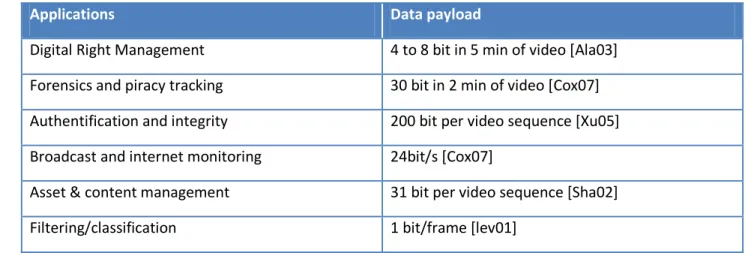
The data payload is the quantity of information that is inserted into the host document. For copyright application, this amount of information should be high enough so as to allow the owner and/or his/her rights to be identified. The data payload can be defined in number of bits within a document or within a unit of time (e.g. bits would correspond to an ISBN number). Different applications require different data payloads, see Table 1.2. For instance, for e-commerce applications, the additional data (the watermark) could bring information about the document buyer, vendor, date and time of purchase. In a right management context, the embedded watermark has to identify the content and specify the usage rules as well as the billing information. For authentication and integrity applications, the watermark details the content’s main modification and the corresponding date of modification.
Table 1.2 Data payload requirements for some examples of watermarking applications.
Applications Data payload
Digital Right Management 4 to 8 bit in 5 min of video [Ala03]
Forensics and piracy tracking 30 bit in 2 min of video [Cox07]
Authentification and integrity 200 bit per video sequence [Xu05]
Broadcast and internet monitoring 24bit/s [Cox07]
Asset & content management 31 bit per video sequence [Sha02]
Filtering/classification 1 bit/frame [lev01]
1.2.2.4. False positive rate
The false positive rate is the number of false positives expected to occur within runs of watermark detection. A false positive is the detection of a watermark in an un-watermarked document. This probability should be as low as possible, but its upper limit is application dependent.
For example, for ownership proof purposes, where the detector is used only when disputing the ownership, the highest accepted value can be considered of . However, for copy control applications the false positive rate should be smaller, e.g. .
1.2.2.5. Computational cost
The computational cost can be determined by calculating the processing time or by defining the algorithmic complexity.
The processing time is calculated in milliseconds and, in some applications must meet the real time requirement: the embedding and detecting modules must not slow down the production schedule. Examples of real time applications include live TV, videoconference, online gaming, community storage solutions and some e-commerce transactions.
The algorithmic complexity is defined as a numerical function – number of operations versus the input size and gives the a priori estimation for the time taken by an algorithm independent of the PC performances.
1.2.3.
From 2D to stereoscopic video watermarking
In its 20 years history, watermarking theory has been already put into practice, for audio, still images, video and 3D objects. While, from the applicative point of view the same properties are searched for, each type of content comes with different methodological frameworks.
Chapter 1: Context
27
Image watermarking
Digital images are often printed and scanned again, downloaded and reused for illustrations. Consequently, many watermarking algorithms have been advanced to protect them from illicit use [Nik98] [Gro01].
The visual quality is obviously crucial in image watermarking which leads to a limited data payload. When used as illustrations, images are often compressed by lossy compression algorithms like JPEG and undergo many other common processing operations including softening, sharpening, denoising, scaling, cropping and colour corrections.
Currently, the most challenging attacks on the robustness of image watermarks are nonlinear transformations, which make the watermark undetectable for the detection algorithm. But even common image processing operations, like scaling and rotations, can be serious challenges for the re-synchronisation of an image watermark.
Another important aspect of image watermarking is the broad variety of image types. There are photos, figures based on line drawings, rendered synthetic images, bitmap representations of textual information, etc… Challenges with respect to transparency and robustness often depend on the characteristics of these image types.
Video watermarking
In the literature, video watermarking has been initially approached as a direct extension of still image watermarking, i.e. by considering a video as a set of still images which are individually protected [Kal99]. However, such straightforward application does not consider the peculiarities of the video content. First, with respect to still images, a larger variety of both hostile and non-hostile processing, such as video editing, lossy compression, filtering, chrominance re-sampling, change of the frame rate during transmission, and formats interchanging, have to be considered. Secondly, in digital video the content is usually dynamic and the human attention cannot focus on all the areas of the video frame simultaneously.
Consequently, for video watermarking, it is of paramount importance to select proper frame regions that can guarantee the data masking, and it is crucial to decide the embedding technique (frame by frame [Bar00], or multiple frames [Kal99]). Given that some particular frame-based attacks (frame dropping, frame exchanging, and frame rate variation) can occur, it seems that frame by frame techniques are preferable, since, in this case, each frame contains the entire watermark, and time synchronization is not needed. Nevertheless, the watermark embedding and recovery can greatly benefit from exploiting the information which is contained in a sequence of frames, i.e. watermark recovery should be performed on a video sequence basis.
Another important issue regarding the video content is related to the possibility of embedding the same watermark in every frame, thus obtaining a system which is sensible to statistical attacks. The other option is to change the watermark from frame to frame with the risk of producing visible temporal artefacts [Hol00].
3D watermarking
3D data is mainly represented by meshes and Non-Uniform Rational Basis Spline (NURBS); these two representations also define the classes of 3D watermarking techniques.
The largest part (more than ) of the studies on 3D data watermarking are mesh-based [Yeo99], no matter if they are devoted to fragile watermarking or to robust watermarking [Lin00] [Bar01a] [Wol99]. Generally, the mesh-based techniques embed the watermark into the vertex positions. Their main problem remains always the robustness. When dealing with NURBS representations, the main advantage is the availability of a natural 2D surface parameterization which makes it possible to extend the 2D watermarking techniques to 3D data. As far as we know, [Lee02] is the first study which exploits the NURBS parametric definition. In this respect the authors advanced a method where the mark is not embedded directly into the 3D model but into some virtual images derived from the 3D model. They propose two methods, the first for steganography and the second for watermarking. For the latter method, three virtual images are obtained by uniformly sampling the 3D model and by recording the , and co-ordinates of the sampled images.
Streoscopic visual content
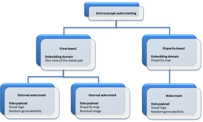
In the watermarking context, the stereo data can be represented in two modalities. The first one simply considers the right and the left views as two independent images. This way, the stereo data can be straightforward exploited with basic 2D methods. However, such an approach has no guaranteed success in the stereoscopic image processing, since it neglects the very intimate mechanisms governing their interdependence. The second modality considers derived representations from the stereo pair, as a disparity map, for instance. Consequently, the stereo watermarking scheme can be classified according to these two directions: view based stereo approaches [Don03a] [Don03b] [Bha09] [Ell09] and disparity based stereo approaches [Zen07].
1.2.4.
Theoretical framework for stereo watermarking
From the theoretical point of view, and independently on the protected data peculiarities, a watermarking technique can be identified within the communication theory as a noisy channel, Figure 1.17: the mark is sampled from the information source and should be sent through a channel where a strong noise (the original content and the malicious attacks) acts. The watermarking challenge consists of optimizing the transmission through this channel, i.e. specifying a method achieving prescribed transparency and robustness while maximizing the data payload. This model shows that transparency, robustness and data payload properties are three-folded antagonistic constraints in the design of a watermarking scheme. First, for a fixed data payload, the more transparent the mark, the lower its power at the transmitter, hence the lower its robustness. Second, for a fixed robustness, the larger embedded amount of data, the lower watermark transparency. Third, for a fixed transparency, the more robust the mark, the lower the data payload.
Chapter 1: Context
29
Figure 1.17 Watermarking as a noisy channel.
In the stereoscopic context, the original content is defined by the right and the left images composing the same scene, Figure 1.18. Hence, the corresponding noisy channel is affected by an extra noise source comparing to the 2D-video model. The main issue is still to maximize the data payload on such a channel, under an additional power constraint set by the human visual system. However, when extending this model to the stereoscopic video case, three more issues should be dealt with. First, the theoretical probability density functions modeling the various transforms the stereoscopic video suffers during its distribution are not yet investigated. Secondly, the two stereo views represent correlated side information noise sources; no theoretical result is nowadays available for handling such a situation. Finally, the human stereoscopic vision is not yet modeled with precision, at least not so as to be directly integrated as a power limit constraint for the inserted mark.
Figure 1.18 The theoretical model for stereo noisy channel.
Recovered message m~ Decryption key Encryption key Input message m Channel Attacks Watermark detection Original content Watermark generation Recovered message m~ Decryption key Encryption key Input message m Channel Attacks Watermark detection
Original right content Original left content
Watermark generation
1.3. Thesis structure
In order to investigate the practical impact the watermarking technique can have for stereoscopic video content protection, this thesis is structured as follow.
The second Chapter is composed of two main parts. The first stands for a state-of-the-art of the disparity map computation algorithms and the second presents a critical overview of stereoscopic watermarking approaches.
Chapter 3 introduces a new disparity map for stereo watermarking scheme. First, the new disparity map algorithm (further referred to as the 3DV-NTSS) is presented and the experimental validation is described.
Chapter 4 explicitly describes the Fast-IProtect stereo embedding technique. First, it introduces the hybrid watermarking technique IProtect and presents its advantage and main drawbacks. Second, it presents the advanced solution to enhance the IProtect performances in terms of computational cost. In Chapter 5, a benchmark of four class of embedding technique applied on four insertion domains is presented.
The last Chapter is devoted to concluding remarks and perspectives.
The thesis has four appendixes. Appendix 1 is devoted to the processed corpora. Appendix 2 presents the considered embedding techniques. The results on the subjective and objective evaluation of the watermarked videos transparency and their corresponding 95% error limits are detailed in Appendix 3. Appendix 4 details the numerical values of the robustness evaluation and their corresponding 95% error limits.
Abstract
This Chapter contains two main parts. The first part presents the state of the art for the disparity map computation methods and compares their performances. The second part introduces the two main directions in watermarking (Spread Spectrum and Side Information) and presents a critical overview of the underlying stereo watermarking approaches. This makes it possible for the thesis main objectives to be identified and positioned with respect to the current day methodological limitations.
![Figure 1.12 Lenticular lens and parallax barrier for autostereoscopic displays [Dod05]](https://thumb-eu.123doks.com/thumbv2/123doknet/11418295.288722/28.918.130.798.105.414/figure-lenticular-lens-parallax-barrier-autostereoscopic-displays-dod.webp)
![Figure 1.15 “Big Buck Bunny” [Ble08], original frame with samples of its attacked versions](https://thumb-eu.123doks.com/thumbv2/123doknet/11418295.288722/35.918.99.817.100.651/figure-buck-bunny-original-frame-samples-attacked-versions.webp)