HAL Id: hal-03188532
https://hal.archives-ouvertes.fr/hal-03188532
Submitted on 3 May 2021
HAL is a multi-disciplinary open access archive for the deposit and dissemination of sci-entific research documents, whether they are pub-lished or not. The documents may come from teaching and research institutions in France or abroad, or from public or private research centers.
L’archive ouverte pluridisciplinaire HAL, est destinée au dépôt et à la diffusion de documents scientifiques de niveau recherche, publiés ou non, émanant des établissements d’enseignement et de recherche français ou étrangers, des laboratoires publics ou privés.
Experimental and Numerical Study of Damages Induced
by Low-Velocity Impact on 4th Generation Composite
Laminates
Salim Chaibi, Christophe Bouvet, Frédéric Laurin, Johann Rannou, Julien
Berthe, Fabrice Congourdeau, Dominique Martini
To cite this version:
Salim Chaibi, Christophe Bouvet, Frédéric Laurin, Johann Rannou, Julien Berthe, et al.. Ex-perimental and Numerical Study of Damages Induced by Low-Velocity Impact on 4th Generation Composite Laminates. American Society for Composites 2020, Sep 2020, Online, United States. �10.12783/asc35/34883�. �hal-03188532�
ABSTRACT
The use of composite fiber reinforced polymer (CFRP) structures in the aircraft industry needs to demonstrate that they satisfy the same safety requirements as for metal structures. Among these requirements, impact damage tolerance is a major sizing criterion for those structures. Impact induce complex out-of-plane loadings that results on large damage extensions. Experimental campaigns are realized at the industrial level to design composite structures but, it induces long and costly development for innovative solutions. Finite Element Model (FEM) is a good tool for sizing efficiently composite components even those exposed to impact. Unfortunately, numerical models developed by academics are too complex to be used in the industry. Besides, due to the highly non-linear problem, explicit solvers are used to avoid convergence issues, which require an expertise in the results verification. In this way, we present a damage model developed at the ONERA [1,2] to predict the progressive rupture of last generation composite laminates subjected to low-velocity impact (LVI)/low-energy impact (LEI). This model has been developed with a fair level of complexity in order to be used in aeronautical industries. This material has thick resin layers at each interface between each plies, which increase the toughness of the laminate. In order to understand damage mechanisms of this specific material when subjected to LVI/LEI, an investigation of impact damages has been carried out in this study. Since LVI/LEI do not enter in the scope of fast transient dynamics, we use an implicit integration scheme and the first results using the damage model are compared with the experimental data given by experimental testing.
1
DMAS, ONERA, Université Paris Saclay F-92322 Châtillon - France
2 MSC ICA Université de Toulouse INSA – ISAE-SUPAERO – Mines Albi – UPS,
Toulouse, 31055, France
3
DMAS, ONERA F-59014 Lille - France
Experimental and Numerical Study of Damages
Induced by Low-Velocity Impact on 4th
Generation Composite Laminates
SALIM CHAIBI1, CHRISTOPHE BOUVET, FRÉDÉRIC LAURIN,
JOHANN RANNOU, JULIEN BERTHE,FABRICE CONGOURDEAU and DOMINIQUE MARTINI
INTRODUCTION
In aeronautics, impact events occurring during ground operations or manufacturing such as tool dropping can induce a 3D accidental loading state. Therefore, when structures made of composite laminates are subjected to LVI, they undergo important strength reduction in compression when subjected to out-of-plane loadings due to their poor performances. Consequently, residual performances can fall up to 50 % of initial strength and must be taken into account for sizing composite structures.
To ensure impact damage tolerance requirements, industrials have developed phenomenological models based on several and costly experimental testing as explained in [3]. The main limitation is the validity framework of these models which are restricted to the impact configuration. Intending to assist industrials, academics have developed numerical models [4, 5] but, although these models provide quite good results, the possibility of using them by engineers in industries is still a challenge. Indeed, such numerical models are quite complex to be used in aeronautical industries. As nonlinearities are introduced such as contact, damage laws, non-linear geometrical formulations, it results on a highly non regular problem. Besides, in order to exempt from convergence problems, explicit solvers are used. The use of explicit solvers needs proficiency in the result analysis, on the top of that, the use of explicit solvers may be out of the habits of some industrials.
These last decades, the understanding of impact damages and especially damages due to delaminations has driven material manufacturers to develop materials in order to improve impact resistance. The enhancement of interfaces between each plies is one of the numerous examples. In our study, the material is a CFRP of last generation tougher than the oldest generation, one of the specificity of this material is that interfaces between each plies are thick. As reported in [6] graphite/epoxy interleaved composites allow the increasing of the interlaminar Mode-II fracture toughness, GIIC, which is an important parameter in impact.
Thus, Dassault Aviation and ONERA have launched a 3 years project called MARCOS 2 with the aim to progress in virtual testing on composite materials for impact tests. A physically based damage model [2] developed initially for in-plane loadings will be enriched to out-of-plane loadings (impact). Furthermore, the validation of the model will be performed on a CFRP laminate made of unidirectional (UD) plies of new generation. The expertise of ONERA and Dassault Aviation in the use of implicit solvers has allowed choosing such a solver to treat the impact problem, and to run post-impact calculation, as compression after impact (CAI).
In this study, the preliminary experimental characterization of the material is presented. Damage investigations by means of 2D (micrographs) and 3D (ultrasonic scan, computed tomography) inspections are conducted after LVI/LEI tests. Then, damage laws are detailed for the intra-ply and inter-ply damages. In order to understand each damage mechanisms, simulation results using cohesive zone model (CZM) are firstly presented, then simulations using both intra-ply and CZM are performed. The interaction between intra-ply matrix cracks and delaminations is then discussed. Finally, a first comparison between experimental results and simulations is presented.
EXPERIMENTAL INVESTIGATION OF IMPACT DAMAGES
In this section, the experimental study of LVI/LEI on a new composite material is presented to :
(i) Identify the different kinds of impact damages which contribute to dissipate the energy such as (delaminations, matrix cracking and fiber failures).
(ii) Observe the damage locations through-the-thickness.
(iii) Quantify which damage mechanisms are leading the material degradation. In order to perform such investigation, assessment of impact damages has been performed with ultrasonic control, optical micrographs, and X-ray tomography (CT).
Material
The specificity of this material is that matrix is an epoxy toughened resin. Studies of similar materials have been performed in [7,8], it has been shown that they are tougher than classical CFRP laminates. In fact, in [8] it is demonstrated that the mode-II fracture toughness GIIc is increased, it can be noted that GIIc is one of the most important parameter to simulate impact because delamination propagates mainly in mode II.
Materials are provided by our partner Dassault Aviation, 4 different laminates are tested and are summarized in the table I.
TABLE I SUM UP OF THE COMPOSITE LAMINATES TESTED
Laminates Numbers of plies Lay-ups (0°/45°/-45°/90°) (A) Quasi-isotropic 16 4/4/4/4
(B) 0° oriented 20 10/4/4/2 (C) 0°/90° oriented 20 8/2/2/8
Experimental set-up
To understand if the damage process of this material is similar as for oldest materials such as T700GC/M21 in terms of classical impact damages (fiber breakages, delamination cracks, matrix cracks), experimental tests have been performed at ONERA. Post-impact inspections (ultrasonic scans, micrographs, X-ray tomography scans) on coupons have been carried out to assess impact damages and, to supply data for comparing with simulation results.
Coupon sizes are 150 mm x 100 mm as recommended by the standard ASTM D7136 [9]. Coupons are simply supported on an impact window as shown in [9], the clamping system recommended in the standard is not used in order to simplify the boundary conditions. The impactor diameter is a 16 mm diameter with a weight of 13.01 kg. An anti-rebound system is used to avoid a second impact. In figure 1, the experimental set-up is presented.
Figure 1 Experimental set-up available at ONERA
Three impact energy levels are considered (11J, 21J, 35J) by modifying the impact velocity and therefore the initial height of the impactor. In terms of instrumentation, a cell load is located within the impactor, the velocity of the impactor is measured by a photoelectric cell and, displacement of the impactor is calculated by integrating twice the acceleration. 2 samples have been tested for each configuration in order to estimate the scattering, table II provides a summary of the experimental campaigns.
TABLE II. SUMMARY OF THE EXPERIMENTAL CAMPAIGNS
Experiment Inspection
Energies Laminates Samples Ultrasonic scans
CT scans
Micrographs Measure of the residual dent 11 J A 2 - B 2 - C 2 - 21 J A 2 B 2 C 2 35 J A 2 B 2 C 2
Results from impact experiments and investigation of impact damages
GLOBAL RESPONSE
After the impact, the following data results are available.
Load over time
Displacement of the impactor over time
These informations have been plotted in figure 2 to evaluate the global response of the material and to observe non-linearities occurring during the impact event. In this paper, only the results obtained on quasi-isotropic laminate (A) are presented.
First of all, it can be seen that scattering is very low especially for the two first levels of impact energy where curves are overlapping.
A first non-linearity is observed around 55% of the maximum load for all energy levels in figure 2a and 2b in black line. This nonlinearity has been observed also in [9] for the T700GC/M21. According to [10], this nonlinearity could be due to plastic deformation of particles during delamination. Therefore, delamination could be responsible of this non-linearity. Furthermore, it has been observed on slice tomography that fiber breakages in compression occur since the first impact energy level and affect the first three plies at the impacted face. Fiber breakages in compression could also explain the loss of stiffness occurring around 55% of the maximum load observed in figure 2a and 2b.
A 37 % global stiffness decrease appears at 100% of the maximum load for the highest energy level (35 J), it seems that the laminate has reached it maximum load-bearing capability. This load drop is due to fiber breakages in tension of the plies located at the opposite of the impacted face.
In figure 2b, a typical load/displacement response is presented. During the loading, curves are superimposed, for the 35 J, it can be noted that after the load drop considerable oscillations can be seen until 90% of the maximum displacement where the unloading stage is quite feeble. The 35 J curve exhibits a different behavior from the other energy levels, which could be explained by large damage extends. Dissipated energies are calculated from figure 2b for the 3 levels of impact energies. Each energy level dissipates gradually (2.4 J, 4.6 J, and 35 J).
In figure 2c, the deformation energy is plotted, it can be seen that all impact energies haven’t been recovered at the end of impact due to dissipated damages. Moreover, at 35 J, almost the energy has been dissipated in damages confirming the presence of higher dissipated mechanisms such as fiber failures.
In figure 2d the residual dent is plotted in function of the energy level, the higher is the energy, the deeper is the residual dent. The figure 2d shows that the evolution of the residual dent is not linear and an important difference can be relieved at 35 J. It could be explained by the increase of fiber breakages in compression at the impacted face which influences the residual dent. As no scattering has been noticed for residual dent, only the first residual dents of first samples have been plotted.
Figure 2 Effects of the impact energy on global responses of quasi-isotropic samples (A)
ASSESSMENT OF DAMAGES
Cut at 0° and 90° have been performed in order to quantify impact damages. Then, micrographs have been performed using scanning electron microscopy (SEM)
at ONERA on quasi-isotropic (A) samples impacted at 21 J. In Figure 3a, we find classical damage mechanisms in composite laminate such as transverse cracks and delaminations at the interface between the 2 plies. Moreover, the strong interaction between matrix cracks due to out of plane shear stresses and delaminations is observed with the presence of fragments. In figure 3b, fiber breakages in compression, well known as fibers kinking are observed. The figure 3b illustrates the interaction between each damages and their complexity. It allows the observation and the comprehension of impact damages but the scenario is still unknown.
Besides, another intra-ply damage mechanism not much known is observed in figure 3b. This damage has already been mentioned in [8] for this specific material and, could be explained by the high toughness of interphase between plies, resulting on easier delamination propagation within the plies and not between them.
Figure 3 Damage patterns observed in SEM for 90° cut on quasi-isotropic (A) sample impacted at 21 J
Ultrasonic scans (US) with 1 mm resolution and X-ray tomography with 23μm resolution allow us to assess the damaged zones through the thickness. In figure 4a, the projected damaged area of delamination obtained by ultrasonic inspection is presented, all metric values are normalized using the highest length (at 35 J) obtained by C-scan. Damaged area grows for the 2 first levels of energy and at 35 J, damaged area grows longitudinally especially for the lower interface in red [0°/45°] due to large delamination cracks interacting with splitting cracks on the last ply. Besides, a -45° oriented crack appears on the impacted surface since the first level of energy (11 J) and is growing with energy levels. C-Scan provides an useful data in impact which is the projected damaged area. The projected damaged area is growing with impact energy (values are normalized using the highest damaged area). Unfortunately, inspection by US is insufficient to understand precisely the damage mechanisms inside the laminate, therefore complementary X-ray tomography have been performed. In figure 5b, a slice of CT-scan from sample impacted at 35 J shows the damage through the thickness, each damage is easily distinguished and allow a better understanding of damage location rather than C-scan. X-ray tomography allows us identifying each kind of damage mechanisms.
In figure 4b, damage segmentation through-the-thickness obtained with computed tomography (CT) scan is presented. From figure 5a, it can be observed that the cracks at -45° observed in C-scan are fiber breakages in compression located at the impacted face. These fibers kinking occur since the first level of energy (11J) and through the 3 first plies. It is due to high compression stress localized close to the impact zone. Concerning the damage extends in figure 4b, despite the fact that the damage patterns obtained with the 2 methods are quite similar, the damaged area obtained by X-ray is always slightly lower than that obtained by C-scan. Same assessment has been reported in [12] and can be explained by the lower resolution of X-ray than C-Scan.For the 2 first levels of energy, no damage is observed under the impact due to compressive pressure that delays the onset of cracks, as observed in [8]. This is discussed in the next section.
Figure 4 (a) Projected damaged area for the 3 energy levels applied on quasi-isotropic samples (A) obtained by C-scan in (a) and CT in (b)
Figure 5 (a) CT volume showing damages on the impacted surface for all quasi-isotropic (A) samples (b) 90° slice showing damages through the thickness for the 35 J sample.
FINITE ELEMENT MODELING APPROACH
In this section, the damage model is firstly detailed with a special emphasize on the intra-ply damage law, then the inter-ply damage model is discussed with the introduction of a new onset criterion that takes into account shear reinforcement in presence of out-of-plane compression. Finally, the results of simulations are analyzed and a first simulation/experiment comparison is performed.
General principle
A multiscale hybrid approach for damage and failure predictions has been proposed in the WWFE-III [1]. During this exercise, the damage model has been evaluated on different test cases for different composite laminate materials. Although this model has predicted accurately the failure in several test cases, it is difficult to use such a complex damage model in industries. Therefore, during the MARCOS project, a simplified model has been proposed [2] with some inheritances from WWFE-III.
The main described sources of non-linearity are summarized in equation 1.
σ = C̃ ∶ (ε − εnl− εve− εth) (1)
With σ is the Cauchy stress ε is the total strain
C̃ is the effective stiffness due to damage with C̃ = S̃−1 εnl is the nonlinear elastic strain
εve is the viscous strain εth is the thermal strain
A DAMAGE MODEL BASED ON OBSERVABLE VARIABLES
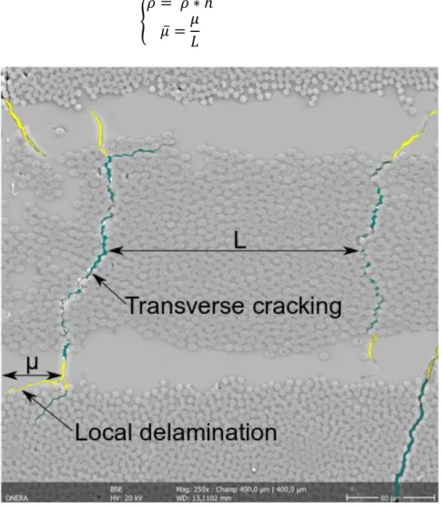
As shown in figure 6, when a transverse crack reaches the interface between 2 adjacent plies, local-delamination appears at crack-tip where the stress gradient is very high. This local-delamination induces the saturation of transverse cracks.
It is important to take into account of matrix cracking because it induces load transfer to the neighborhood and stress concentration which are important to predict ply failure. Therefore, as proposed in [13], 2 damage variables are introduced using observable parameters called 𝜌̅ and 𝜇̅ as shown in equation 2, which are respectively the normalized matrix crack density and the delamination ratio, where L being the length of the interface and h the thickness of the ply.
{
𝜌̅ = 𝜌 ∗ ℎ 𝜇̅ =𝜇
𝐿
(2)
Figure 6 Damage variables observable from SEM micrograph on quasi-isotropic (A) sample impacted at 21 J
A damage model can be decomposed in three main parts (i) onset of damage, (ii) evolution laws and (iii) effect of damages. These parts are described in the following.
DAMAGE ONSET
To create a crack in a UD ply, it is assumed that only 𝜏12, 𝜎22 and 𝜏23 stresses expressed in the material axis can contribute. Therefore, these 3 stresses are taken into account in the calculation of the driving force Y reported in equation 3.
Y =1 2(𝜎22 +2𝑆̃ 22+ 𝜏23+2𝑎24𝑆̃44+ 𝜏12+2𝑎26𝑆̃66) (3) With { 𝑎24 = 8𝑌0−𝑆022 𝑆23𝑅 𝑆044 𝑎26 = 8𝑌0−𝑆022 𝑆12𝑅 𝑆066 (4)
From the equation, it can be relieved that:
The contribution of shear in the driving force Y is led by 2 parameters 𝑎24 and 𝑎26 depending on the shear strength (𝑆12𝑅, 𝑆23𝑅) and on the initial compliance tensor 𝑆0.
Y varies not only with stresses but also with effective compliance which increases with damage.
Positive part of the stress tensor 𝜎+ is used. It allows predicting the apparent reinforcement of the strength obtained for combined shear/compression loading.
It is assumed that the onset of transverse cracking is reached when the driving force threshold 𝑌0 detailed in equation (5) is achieved.
Y0 =1 2(Y
T2S 0 22)
(5)
The threshold is identified using the in-situ transverse strength 𝑌𝑇. Due to the strongly
dependency of the damage threshold to the ply thickness, the in-situ strength is expressed using 2 complementary criteria (a stress criterion and an energetic criterion) that have to be fulfilled for damage onset. The in-situ strength 𝑌𝑇 is determined based on the work of [14]. In order to obtain accurate onset of damage for shear loadings the (𝑎24, 𝑎26) parameters are considered and depend on the shear strength. The in-plane strength 𝑆12𝑅 is calculated using [15] methodology. As no Interlaminar Shear Strength (ILSS) tests haven’t been yet performed, the resistance 𝑆23𝑅 is used from T700GC/M21.
DAMAGE EVOLUTION LAW
Once the driving force Y becomes higher than the threshold 𝑌0, damage is initiated, and evolves thanks to a damage evolution law defined in equation 6, proposed firstly in [1].
A strong coupling between 𝜌̅ and 𝜇̅ has been introduced, as noticed in [13], local delamination tends to slow down the evolution of transverse cracks.
𝛼𝐼, 𝑛 are material parameters which control the damage kinetics of transverse cracking, 𝑎ℎ and 𝑏ℎ being also material parameters that control local delamination kinetics.
It can be seen that for thicker plies, transverse cracks and local-delaminations will be more important due to the introduction of the ply thickness h in the equation 6. {ρ̅ = (1 − μ̅)ℎ𝛼𝐼〈Y − Y0〉 𝑛 + μ̅ = 〈ahρ̅2+ bhhρ̅〉+ (6) DAMAGE EFFECT
These two damage variables affect the effective stiffness matrix as exposed in equation 7. The effective compliance is calculated by adding to the initial elastic compliance S0 , fourth order tensors to express damage effects in the different directions of the material.
The effect tensors HX (with x ∈ (a, b, c)) are diagonal tensors, the different parameters ahead of tensor effects are identified numerically.
Indeed, stiffness reduction is determined numerically thanks to finite element simulations on a representative elementary volume (REV) with a discrete crack as proposed in [1, 2, 13]. The effect tensors are therefore determined by homogenization knowing only the 3D elastic properties of a composite material.
S̃ = S0+ ρ̅Ha+ μ ̅ 1−μ̅Hb+ ρ ̅2 1−μ̅Hc (7) Delamination modeling
To model delamination, a cohesive zone model has been considered. A damage model is associated with interface elements with initial zero-thickness introduced between plies with different orientations. Such a damage model can be decomposed in two parts, (i) the onset of delamination and (ii) the delamination propagation. An initial elastic stiffness is associated with the interface element fixed here at 106 MPa/ mm, as it is widely used in the literature and allows a good compromise between convergence and spurious softening of the structure.
ONSET CRITERION
2 criteria have been considered for the onset of delamination :
Quadratic criterion based on Yeh and Stratton criterion (〈σ33〉+ Zt ) 2 + (τ13 Sc ) 2 + (τ23 Sc ) 2 = 1 (8)
Where 〈−〉+ is the Macauley bracket, 𝑍𝑡 is the out-of-plane tensile strength and 𝑆𝑐 is the out-of-plane shear strength. It is assumed that the out-of-plane shear strength associated to τ13 is equal to that associated with τ23.
Quadratic criterion with a strength reinforcement under combined shear/out-of-plane compression [16] (σ33 + Zt ) 2 + (τ13 + Scr) 2 + (τ23 + Scr ) 2 = 1 (9)
Where σ+ corresponding again to the positive part of the stress. For the first classical criterion, it is assumed that the onset of delamination due to shear is insensitive to the level of out-of-plane compression (σ33< 0). But experimentally, it has been reported in [17,18] that through-thickness compressive stress delays the delamination onset and increases the mode-II interlaminar fracture toughness GIIc. During an impact, the presence of a high gradient of through-thickness compressive stress under the impactor has led us to consider the second onset criterion. It has been developed in [16] for bolted joint problem with pre-loading but hasn’t been tested for impact test.
In figure 7, the two onset criteria are compared. Using the first criterion, the onset of delamination doesn’t evolve with through-thickness compression σ33. Whereas, for the second criterion the failure onset evolves with through-thickness compression.
PROPAGATION CRITERION
Benzeggagh-Kenane criterion [19] is used to model delamination propagation. The criterion reported in equation 10, is formulated with interlaminar fracture toughness. Double cantilever beam (DCB) and mixed-mode bending (MMB) have been performed for this material in [2] to identify interface properties. 4-point end notch flexure (ENF) should be performed soon to consolidate the identification of the mode II fracture toughness.
𝐺𝑐 = 𝐺𝐼𝑐+ (𝐺𝐼𝑐− 𝐺𝐼𝐼𝑐) ( 𝐺𝐼𝐼𝑐
𝐺𝐼𝑐 + 𝐺𝐼𝐼𝑐+ 𝐺𝐼𝐼𝐼𝑐) 𝜂
(10)
Finite element model
The proposed finite element model simulates the impact experiments on 150 mm x 100 mm laminated samples. The sample is simply supported on an impact window of 125 mm x 75 mm. The sample is impacted by a 13.01 kg impactor, with an initial velocity of 1.8 m. s−1corresponding to a 21 J impact. Each ply of the composite laminate is meshed using a solid element as presented in figure 8. Interface elements are introduced to model delamination between each ply. The damage model is associated with each ply. The impactor and the impact window are meshed using solid elements, the behavior of the impactor and the impact window are assumed isotropic linear elastic using the properties E=200 GPa and ν=0.3. Contact without friction is used with a penalty contact law for the impactor/laminate and laminate/impact window. The assumption for small displacement is not relevant, geometric nonlinearity is thus taken into account.
Despite all the non-linearities and convergence issues, a dynamic implicit
scheme (HILBER-HUGHES-TAYLOR method) is used. The FE simulations have
Analysis and discussion of calculation results
5 simulations summarized in table III, are compared. Firstly, the effect of the two onset criterion on delamination is analyzed in the simulations 1 and 2. Simulations 1 and 2 were run with CZM using interface elements between each ply and without intra-ply damage law. The simulation 3 was run with only intra-ply damage law for each ply in order to study the effect of matrix cracking and to visualize the shape of matrix cracks. Then, the simulations 4 and 5 were carried out using intra-ply damage model and CZM to study how damages (inter-ply/intra-ply) interact. Finally, a comparison of simulations 4 and 5 are made with the experimental results in terms of the global response and projected delaminated area.
TABLE III. FINITE ELEMENT SIMULATIONS SUMMARY
INFLUENCE OF ONSET CRITERION ON DELAMINATION
In figure 4b, X-ray tomography have relieved that for the impact energy at 11J and 21J, no damages are localized under the impact. In fact, under combined shear/out-of-plane compression, shear reinforcement is observed experimentally. Therefore, the second onset criterion has been used in simulation 2, in order to study the influence of the onset criterion on damage extend. By using the second onset criterion, the onset of damage under the contact zone (i.e. where a high through the thickness compressive stress gradient is present) is delayed due to the reinforcement of the material in presence of out-of-plane compression.
In figure 9, projected delaminated area is presented between simulation 1 and 2 for the front (impact side) and rear views. In this figure, all damaged Gauss points (d >0, where d being the damaged variable) are shown, the figure is observed as a C-scan in depth with 0 being the impacted face and 1 being the non-impacted face for the front view.
Delamination patterns are differents between simulations 1 and 2. Thus, by taking into account the shear reinforcement, a significant change on the delamination extend is observed. In figure 9, the simulation 2 using the reinforcement criterion is getting closer from the experimental assessment than simulation 1, indeed on the rear view, the first interfaces are more damaged as seen in the tomography. Moreover, as shown in figure 10, the simulation 2 allows a delamination distributed more regularly for each interface.
Damage model CZM Delamination Onset criterion Simulation 1 - Yeh and Stratton Simulation 2 - Reinforcement Simulation 3 - -
Simulation 4 Yeh and Stratton Simulation 5 Reinforcement
Figure 9 Comparison of the delamination extends in the simulations 1 and 2
Figure 10 Edge view of the delaminated interfaces for the simulations 1 and 2
INFLUENCE OF INTRA-PLY DAMAGES
In figure 11, 3 cuts are exposed which are respectively simulations 3, 4 and 5. As shown in figure 11, the rectangle in red dotted line represents the cut. The first slice (simulation 3) shows the conical shape observed experimentally during impact. It is interesting to note that no matrix damage are present under the impact, but matrix damages are present in the vicinity of the non-impacted face due to high positive bending stresses σ22.
By comparing the simulation 3 with the simulations 4 and 5, the introduction of interface elements with CZM changes in a meaningful way the matrix crack shapes. As delamination cracks propagate, the initial laminate flips through sub-laminates
In figure 12, the effect of intra-ply damage on the delamination extend is shown. By comparing, for fixed onset criteria, the simulation with CZM and elastic behavior and simulation with intra-ply damage + CZM, it can be relieved that the matrix cracks have an influence on delamination extend. The influence of intra-ply damage on delamination is higher using the reinforced onset delamination criterion, especially at the rear side. In fact, transfers loading of damaged gauss points due to matrix cracks effects on the neighborhood, induce modifications in delamination onset.
Figure 11 Longitudinal cut under the impact showing matrix cracks and delamination shape for the simulations 3, 4 and 5
TOWARD SIMULATION-EXPERIMENT COMPARISON
A first comparison is illustrated in figure 13 between the simulations 4 and 5 and the experimental results at 21 J. Values are normalized using the experimental results. For the macroscopic behavior, it can be seen that the global impact response is almost the same for the 2 simulations even if delamination patterns are quite different.
The global behavior of the laminate is well reproduced until 55% of the load and then simulations are getting stiffer. It could be explained by the fact that fibers kinking under the impactor are not yet taken into account in the current model, resulting on underestimated dissipated energies as seen in figure 13. A damage model for fiber failure in tension and compression will be developed soon.
In figure 14, projected delaminated area for the front and the rear views are shown. The extent of damages is higher in simulations forecasting than obtained by X-ray tomography. As explained previously, fibers damage are not taken into account actually, therefore, the two only dissipative mechanisms are matrix cracking and delamination which will surestimate the dissipated energy by those mechanisms. Besides, the value of GIIc has been fitted using the mixed mode bending curves for a 100 % mixity. For this kind of material, the impact toughness is linked to the increase of GIIc. 4 points-ENF test will be performed soon to estimate rigorously GIIc value. For the rear view, the simulation 5 (using the reinforcement criterion) seems to show a better agreement with the experiment than the simulation 4.
Figure 13 Macroscopic comparison of load-displacement curves between tests and simulations on (A) laminate for 21 J impact energy
Figure 14 Local comparison of delaminated projected area between test and simulations on (A) laminate for 21 J impact energy
CONCLUSIONS
Conclusions and outlooks
A first study has been presented on LVI/LEI for a carbon/epoxy composite interleaved laminate. The data obtained from inspections allowed us understanding the damage pattern obtained after the LVI/LEI in a new generation of UD ply material. However, questions remain. All of inspections have been performed after impact event, therefore, the evolution of damages hasn’t been monitored during loading. To validate the damage model, it seems relevant to understand how damage kinetics evolves and how the different damage mechanisms interact with each other. To do so, modifications of our impact experimental device have been performed. It will allow to monitor damage in real-time by adding high-speed infrared and optical cameras for digital image correlation in order to establish precisely the damage scenario.
Numerically, an intra-ply damage model based on observable variables has been introduced in order to simulate LVI/LEI on an industrial CFRP laminate. This model has been identified and validated previously in [2] for in-plane loadings and will be enhanced for out-of-plane loadings. Impact simulations have been performed using the in-house Z-set code. Despite the complexity of the problem, simulations have been carried out with a dynamic implicit scheme and first comparisons with experimental data have been performed. Results have shown that the current limitation of the numerical model is the non-introduction of a fiber damage law to simulate the progressive but violent degradation of mechanical properties of fiber breakage. Therefore, the numerical model will be improved taking into account the fiber breakage in tension and compression in a near future.
REFERENCES
1. F. Laurin, 2013.‘‘A multiscale hybrid approach for damage and final failure predictions of composite structures’’,Journal of Composite Materials, 47:20-21.
2. J.Germain, 2019, ‘‘Evaluation des capacités prédictives et de la robustesse de modèles à bases physiques pour la prévision de la tenue des structures composites présentant des singularités géométriques ’’, Doctorate thesis of Université Paris-Saclay.
3. C.Fualdes, 2006. “Composite Airbus damage tolerance methodology”, presented at the FAA Workshop for Composite Damage Tolerance and Maintenance, July 19-21.
4. C.Bouvet, S.Rivallant, J.J.Barrau, 2012. ‘‘Low velocity impact modeling in composite laminates capturing permanent indentation’’,Composites Science and Technology, 72(16):1977-1988.
5. A.H.Baluch, 2019. ‘‘An efficient numerical approach to the prediction of laminate tolerance to Barely Visible Impact Damage’’, Composite Structures, 225, 111017.
6. A.Aksoy, 1992, “Interlaminar shear fracture of interleaved graphite/epoxy composites”, Composites
Science and Technology, 43 55-69.
7. V.Priasso, 2017, ‘‘Modélisation multi-échelle de l'endommagement des composites stratifiés avec intercouches’’, Doctorate thesis of Université Paris-Saclay.
8. D.J.Bull, 2014 ‘‘Damage assessment of particle-toughened carbon fibre composites subjected to impact and compression-after-impact using 3D X-ray tomography’’, doctorate thesis of university of Southampton.
9. ASTM D 7136/D 7136M 07, 2007, “Standard test method for measuring thedamage resistance
of a fiber-reinforced polymer matrix composite to a drop-weight impact event”, ASTM
International.
10. Yi Liv, 2017. ‘‘Experimental study into compression after impact strength of laminates with conventional and nonconventional ply orientations”, Composites Part B,126:133-142.
11. F.Gao, 2007. ‘‘Mode II Delamination and Damage Resistance of Carbon/Epoxy Composite Laminates Interleaved with Thermoplastic Particles”, Journal of Composite Materials, 41:11-123.
12. F.Léonard, 2017. ‘‘The quantification of impact damage distribution in composite laminates by
analysis of X-ray computed tomograms’’, Composites Science and Technology, 152:139-148.
13. C.Huchette, 2005, ‘‘Sur la complémentarité des approches expérimentales et numériques pour la
modélisation des mécanismes d'endommagement des composites stratifiés, , Doctorate thesis of Université de Paris 6.
14. G. J.Dvorak, 1987, ‘‘Analysis of Progressive Matrix Cracking In Composite Laminates II. First Ply Failure’’,Journal of Composite Materials, 21:309-329.
15. Camanho, 2006, ‘‘Prediction of in situ strengths and matrix cracking in composites under
transverse tension and in-plane shear’’, Composites Part A: Applied Science and Manufacturing, 37:165-176.
16. T.Vandellos, 2011, ‘‘Développement d’une stratégie de modélisation du délaminage dans les
structures composites stratifiées’’, Doctorate thesis of Université de Bordeaux 1
17. G.Catalanotti, 2017, ‘‘The effect of through-thickness compressive stress on mode II
interlaminar fracture toughness’’, Composite Structures, 182:153-163.
18. Xiangqian Li, 2007,‘‘Predicting the effect of through-thickness compressive stress on
delamination using interface elements’’, Composites Part A ,39: 218–230.
19. M.L.Benzeggagh, 1995, ‘‘Measurement of mixed-mode delamination fracture toughness of
unidirectional glass/epoxy composites with mixed mode bending apparatus’’, Composites Science