is an open access repository that collects the work of Arts et Métiers Institute of Technology researchers and makes it freely available over the web where possible.
This is an author-deposited version published in: https://sam.ensam.eu Handle ID: .http://hdl.handle.net/10985/7469
To cite this version :
Guillaume FROMENTIN, Gérard POULACHON - Geometrical analysis of thread milling – Part 2:Calculation of uncut chip thickness - The International Journal of Advanced Manufacturing Technology - Vol. 49, n°1-4, p.81-87 - 2010
1 2 3 4 5 6 7 8 9 10 11 12 13 14 15 16 17 18 19 20 21 22 23 24 25 26 27 28 29 30 31 32 33 34 35 36 37 38 39 40 41 42 43 44 45 46 47 48 49 50 51 52 53 54 55 56 57 58 59 60 61 62 63
Geometrical analysis of thread milling – Part 2:
Calculation of uncut chip thickness
G. Fromentin, G. Poulachon
Arts et Metiers ParisTech, LaBoMaP, 71250 Cluny, France Email: guillaume.fromentin@cluny.ensam.fr
Tel.: +33 3 85 59 53 30 Fax: +33 3 85 59 53 70
Keywords: thread milling, uncut chip thickness
Abstract: Thread milling offers interesting possibilities for machining internal or external threads. This machining technique uses a mill with a triangular profile for metric threads and a helical interpolation
strategy. Thus, the uncut chip thickness can not be easily evaluated from a simplified approach. The present study deals with a model for calculating uncut chip thickness during internal thread milling. This step is needed to understand and model the cutting forces. The model developed uses the geometrical definitions of the mill, and takes into account the milling mode and the cutting conditions. The link with the interferences between the tool and the thread is also established and corroborates a previous study. A full analytical formulation of the problem is proposed, and results from different milling settings are presented.
*Manuscript
2 3 4 5 6 7 8 9 10 11 12 13 14 15 16 17 18 19 20 21 22 23 24 25 26 27 28 29 30 31 32 33 34 35 36 37 38 39 40 41 42 43 44 45 46 47 48 49 50 51 52 53 54 55 56 57 58 59 60 61 62 NOMENCLATURE
Subscripts and abbreviations: m relative to the mill
t relative to the thread r,θ,z cylindrical coordinates fce: front cutting edge uce: upper cutting edge lce: lower cutting edge Referentials and parameters:
RO = (O,E1,E2,E3) referential linked to the thread (O,E3): hole axis
Ro = (o, e1,e2,e3) referential linked to the mill with E3 = e3 and ∠( 1111, 1111)= Θ E e E e E e E e
t: time
θ: angular position of the mill
Θ:angular position of the mill axis
zce: altitude of a cutting edge point in the Ro referential u: parameter
Metric thread dimensions:
D: nominal diameter of the internal thread D1: minor diameter of the internal thread D2: pitch diameter of the internal thread P: thread pitch (mm)
p: angular thread pitch (mm/rad)
td: thread direction (right-hand thread td = 1, left-hand thread td = -1) kt: reduction coefficient of the thread profile height
Mill dimensions:
Dm: maximum diameter (mm)
km: reduction coefficient of the mill profile height nfm: flute number
pfm: pitch per radian of the helicoidal flute
2 3 4 5 6 7 8 9 10 11 12 13 14 15 16 17 18 19 20 21 22 23 24 25 26 27 28 29 30 31 32 33 34 35 36 37 38 39 40 41 42 43 44 45 46 47 48 49 50 51 52 53 54 55 56 57 58 59 60 61 62 63
γom: orthogonal rake angle
λsm: flute angle (or helix angle) on the Dm diameter Cutting parameters:
Vc: cutting speed (mm/min) ft: feed rate (mm/rev/tooth) rdoc: radial depth of cut (mm) rp: radial penetration (mm)
Rmc: helix radius of the mill center trajectory (mm)
mm: milling mode (down-milling mm = 1, up-milling mm = -1) Geometrical objects:
MC(t): mill center trajectory MP(zce): mill profile
RF(r,zce): mill rake face (flute surface) CEi(zce): i
th
mill cutting edge SCEi(t,zce): surface generated by i
th
mill cutting edge ADSCE(i,t,zce): distance from SCEi to the hole axis NVSCE(i,t,zce): normal vector with respect to SCEi NLSCE(i,u,t,zce): normal line with respect to SCEi NTS(θ,z): nominal thread surface
Computing parameters:
ft12: feed rate projected onto plane (e1,e2) (mm/rev/tooth) Ss: spindle speed (rpm)
ω: mill rotation speed (rad/s)
Ω: mill axis rotation speed (rad/s) Vf: feed rate (mm/min)
tc: undeformed chip thickness (mm)
Ea: axial error between nominal and generated thread (mm) Operators:
2 3 4 5 6 7 8 9 10 11 12 13 14 15 16 17 18 19 20 21 22 23 24 25 26 27 28 29 30 31 32 33 34 35 36 37 38 39 40 41 42 43 44 45 46 47 48 49 50 51 52 53 54 55 56 57 58 59 60 61 62 R(θ): rotating operator cos( ) sin( ) 0 ( ) sin( ) cos( ) 0 0 0 1 θ θ θ = − θ θ R N(V): normative operator N V( )= 1 V V
2 3 4 5 6 7 8 9 10 11 12 13 14 15 16 17 18 19 20 21 22 23 24 25 26 27 28 29 30 31 32 33 34 35 36 37 38 39 40 41 42 43 44 45 46 47 48 49 50 51 52 53 54 55 56 57 58 59 60 61 62 63
1 Introduction
Thread milling is becoming a more and more used method for producing internal and external threads [1-2], which is especially interesting for producing high cost parts as mention in [3-4]. This milling technique allow greater cutting speed compared to tapping and then could be adapted for machining difficult to cut materials. Thread milling cycle apply a helical interpolation and it is described in [3].
Thread milling improvement, tool geometry optimization are needed for cutting force analysis. There exists many studies on cutting force modelling, but quite a few deal with mutli-edge form tools which is usually not the case in milling. Mutli-edge form tools is a specific aspect linked to threading techniques. The case of vee groove tools has been studied [5,6], nevertheless threading tool also include a front cutting edge that should have a significant effect and then it can not be considered like vee groove tool. In tapping, only the front cutting edge is working [7,8]. As a consequence, there are two aspects to deal with the cutting force modelling in thread milling: cutting force model linked to edge form, and uncut chip thickness calculation. There are several difficulties to execute the
calculation of the chip area in thread milling. It is because the mill has a triangular profile and also that a helical interpolation is required to machine the thread. It results in a complex 3D geometrical problem, and a simplified approach for that has been proposed [9].
The present study deals with the computation of uncut chip thickness (tc). It takes into account likely considerations concerning the cutting edge (CE) [4] and a full analytical formulation is proposed to produce a more precise model than those which consider a sine function. Knowledge of the uncut chip thickness (tc) is needed for process control and force modelling, and is useful to complete existing studies [9]. Moreover, it is necessary to analyse the effect of tool design parameters, such as the flute angle. Finally, the
calculation of the uncut chip thickness (tc) enables the effect of the milling mode to be evaluated.
This article is related to [3-4] and the general context is identical. It also considers metric thread milling and the same notations are used. Fig. 1 defines the parameterization of an internal thread milling operation which is used. All calculations are computed using Mathematica software. For the different cases studied, the common model parameter values are: D = 16 mm, P = 2 mm, kt = 1/8, Dm = 12 mm, nfm = 5, km = 1/8, Rmc = 2 mm, ft = 0.15 mm/rev/tooth
2 3 4 5 6 7 8 9 10 11 12 13 14 15 16 17 18 19 20 21 22 23 24 25 26 27 28 29 30 31 32 33 34 35 36 37 38 39 40 41 42 43 44 45 46 47 48 49 50 51 52 53 54 55 56 57 58 59 60 61 62
2 Parameterization of thread milling
The milling machine moves the mill center (MC) along a circular helix. Equation (1) defines the mill axis rotation speed [3]. Based on the milling mode (mm) and the thread direction (td), the mill center trajectory (MC) is expressed by the equation (2) [1] in the RO referential. Table 1 sums up the combinations of coefficients mm and td. The sign of the mill axis rotation speed is the consequence of the chosen milling mode (mm).The thread direction (td) conditions the sign of the mill axis speed of the mill center trajectory (MC).
(
)
m fm t mc m .n .f . 2 . p² R ² Ω = ω π + (1) T mc mc d (t)= R .cos( .t), RΩ .sin( .t), t .p. .tΩ Ω MC [ ] (2)The thread profile comes from standard [10] and the mill profile (MP) is resulting from it as explain in [3]. To define cutting edges, it is necessary to have expressions of the mill profile (MP) and the rake face (RF). The formulations used are those defined in [4]. Thus the ith cutting edge (CEi) can be expressed by equation (3) in the Ro referential.
i(z )ce = (2 .(i 1) / n ).π − fm (z , MP (z ))ce r ce
CE R RF (3)
3 Uncut chip thickness calculation
The surface generated by the ith cutting edge (SCEi) is obtained from the mill rotation and the mill center trajectory (MC). It is expressed by equation (4) in the RO referential. Based on equation (2), equation (5) is deduced.
i(t, z )ce = (t)+ (−ω.t). i(z )ce
SCE MC R CE (4)
T
i(t, z )ce = Rmc.cos( .t), RΩ mc.sin( .t), t .p. .tΩ t Ω + (−ω.t). i(z )ce
SCE [ ] R CE (5)
It is intended to limit the surface generated by the ith cutting edge (SCEi) to the work material. That may be done by considering the axial distance (ADSCE) from this surface to the hole axis. This distance is simply expressed by equation (6). If the hole diameter is equal to the minor diameter of the thread (D1), then equation (7) is the condition for the surface generated by the ith cutting edge (SCEi) to be within in the limits of material. Fig. 2 represents these surfaces for the case under study.
2 3 4 5 6 7 8 9 10 11 12 13 14 15 16 17 18 19 20 21 22 23 24 25 26 27 28 29 30 31 32 33 34 35 36 37 38 39 40 41 42 43 44 45 46 47 48 49 50 51 52 53 54 55 56 57 58 59 60 61 62 63
(
) (
2)
2 SCE ce i ce 1 i ce 2AD (i, t, z )= SCE(t, z ).E + SCE(t, z ).E (6)
SCE ce 1
AD (i, t, z )>D / 2 (7)
The uncut chip thickness (tc) is considered as being the normal distance from the surface generated by the ith cutting edge (SCEi) to the surface generated by the i-1th cutting edge (SCEi-1), as shown in Fig. 3. The normal vector with respect to surface (SCEi) can be evaluated by equation (8). Consequently, the normal line with respect to the surface generated by the ith cutting edge (NLSCE) can be expressed by equation (9). Then, at a
given point SCEi(t1,zce1), the uncut chip thickness (tc) may be evaluated by solving
equation (10) numerically, (tc,t2,zce2) values are calculated. If a negative value is obtained for tc, it indicates that the CEi cutting edge extends further than the CEi-1 cutting edge. Thus, the CEi cutting edge is clear of the work material because this was previously removed by the CEi-1 cutting edge.
SCE ce i ce i ce ce (i, t, z ) (t, z ) (t, z ) t z ∂ ∂ = ∂ ×∂ NV N SCE SCE (8)
SCE(i, u, t, z )ce = i(t, z ) u.ce + SCE(i, t, z )ce
NL SCE NV (9)
SCE(i, t , t , z )c 1 ce1 = i 1− (t , z2 ce2)
NL SCE (10)
4 Analysis of the uncut chip thickness
4.1 Case studiedThe previously explained method is applied to a particular case. It is shown that the uncut chip thickness (tc) is a function of both time (t) [the angular position of the tooth (θ)], and the altitude (zce) of the cutting edge point.
Fig. 4 represents the uncut chip thickness (tc) during tooth engagement by cutting edge point Pm0. This point is the mid point of the front cutting edge (fce), i.e. zce is equal to half the pitch. The uncut chip thickness (tc) decreases from a maximum value of 0.139 to 0 mm when the tooth moves clear of the work material. This is expected, because at the
considered point the result resembles cylindrical down milling, even if this result includes the fact that there is a helical interpolation.
The maximum value of the uncut chip thickness (tcfce) may be analytically approximated. The feed (ft12) projected onto plane (E1,E2) is expressed by equation (9). The radial depth
2 3 4 5 6 7 8 9 10 11 12 13 14 15 16 17 18 19 20 21 22 23 24 25 26 27 28 29 30 31 32 33 34 35 36 37 38 39 40 41 42 43 44 45 46 47 48 49 50 51 52 53 54 55 56 57 58 59 60 61 62
of cut (rdoc), if the hole diameter is equal to the minor diameter of the thread (D1), is given by equation (10). Thus, the value of the uncut chip thickness (tcfce) removed by the front cutting edge (fce) can be evaluated by equation (11). For the case studied, this is an approximation, with only 1% error, of the exact uncut chip thickness (tc).
1 2 t12 t mc p f f 1 R − = + (9) doc m 80 3D 75.P r P 256(D D ) − = − (10) doc doc fce t12 m m r r tc 2.f . 1 D D = − (11)
Fig. 5 represents the thickness (tc) along the cutting edge at a fixed time. Globally the front cutting edge (fce) cuts a greater thickness than the upper and lower cutting edges due to the different cutting edge angle. In the present case, with a right-hand thread and down-milling mode, the mill axis speed is positive, and the upper cutting edge (uce) is in this direction. As a consequence, the thickness (tc) cut by the upper cutting edge (uce) is greater than that cut by the lower cutting edge (lce).
Locally, at the points where the front cutting edge (fce) and the flank cutting edges join, the uncut chip thickness (tc) rises to higher values, which can easily be understood by
observing the geometric construction in Fig. 3. This is due to the fact that the cutting edge is only a C0 continuous parametric function. If a cutting edge with corner radii were
considered, this result might not be observed or would not be so large. As a consequence, force modelling by a cutting edge discretization method can not be applied in this zone because the segments are not independent. However, this part of the chip area is
negligible compared to the whole chip area, and may therefore be omitted from the model. Instead of discretizing the cutting edge into segments, a model with a global area
approach can be considered, as proposed by Armarego [5-6] with a full triangular cutting edge (vee groove tool).
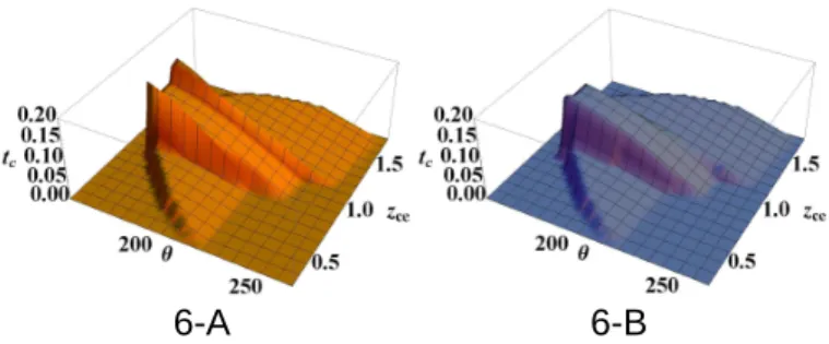
Fig. 6 represents uncut chip thickness (tc) as a function of the angular position of the tooth (θ) and the altitude (zce) of the cutting edge point. The two previous figures show cross section curves of the surface in Fig. 6-A. The surface representing the uncut chip
thickness (tc) in Fig. 6-B is corrected in order to suppress high local values produced at the points where the front cutting edge (fce) and the flank cutting edges join. In addition to the previous observations, it can be added that the upper cutting edge (uce) is engaged for a
2 3 4 5 6 7 8 9 10 11 12 13 14 15 16 17 18 19 20 21 22 23 24 25 26 27 28 29 30 31 32 33 34 35 36 37 38 39 40 41 42 43 44 45 46 47 48 49 50 51 52 53 54 55 56 57 58 59 60 61 62 63
longer time than the lower one (lce). Furthermore, over the time a wider portion of the cutting edge (CE) engages the workmaterial, while the uncut chip thickness (tc) decreases.
4.2 Effect of milling mode and thread direction
Other computations of uncut chip thickness (tc) are made at different settings, by changing the thread direction (td) and milling mode (mm). The results are presented in Fig. 7. In down-milling mode, the uncut chip thickness (tc) decreases as a function of time; it is the opposite case for up-milling. Moreover, the flank cutting edges in the direction of axial speed (refer table 1), remove greater chip thickness. Thus, this cutting edge can be either the lower cutting edge (lce) or the upper cutting edge (uce), depending on both the milling mode and the thread direction.
There exists a practice to balance the wear on the two flank cutting edges. It consists of milling a thread in two passes and changing the milling mode between the two. This practice may be explained because the change in milling mode reverses the uncut chip thickness of the flank cutting edges.
It is demonstrated [4] that there is negative cutting on the upper cutting edge (uce) of mills having too high a flute angle. If the work material may be cut in both milling modes, in order to reduce cutting forces it would be interesting to mill the thread such that the uncut chip thickness is lower on this upper cutting edge (uce). Thus, with such a kind of mill, a right-hand thread should be up-milled and a left-hand thread should be down-milled.
4.3 Effect of milling geometry
In flank milling with a cylindrical mill, the flute angle induces an angular delay on the uncut chip thickness (tc) at each point of the cutting edge. In thread milling, the flute angle (λsm) and the orthogonal rake angle (γom) both lead to an angular delay. As shown in Fig. 8, with a straight flute mill having no rake angle, a wider portion of the upper cutting edge (uce) is engaged compared to a helical flute mill. Furthermore, the uncut chip thickness is strictly constant along the flank cutting edges at a fixed time. The difference between these two mills may not appear as significant; nevertheless when the mill is completely engaged axially, the effect of the flute angle (λsm) participates significantly to reduce the chip area at a given time. It can not be concluded that flute angle may contribute to reduce cutting forces, because this angle also induces a negative rake angle [4]. Thus, there exists an optimized flute angle value to reduce cutting forces which may avoid effect of large negative rake angle [11].
2 3 4 5 6 7 8 9 10 11 12 13 14 15 16 17 18 19 20 21 22 23 24 25 26 27 28 29 30 31 32 33 34 35 36 37 38 39 40 41 42 43 44 45 46 47 48 49 50 51 52 53 54 55 56 57 58 59 60 61 62
5 Interference analysis
It is usually that machining with form tools induces interference (overcut or undercut) and machined surfaces are not exactly as the nominally ones. It is concerned with many cases like: worm, grooves grinding or milling [12-13], threads grinding [14], or flank milling of free form surfaces [15].
The milling of threads also leads to interference. There is an overcut on the nominal thread surface (NTS), as presented in [3]. The approach which was developed considered the mill envelope (ME). A second approach is now developed, directly based on the surface
generated by the ith cutting edge (SCEi).
It can be established from test equations whether the surface generated by the ith cutting edge (SCEi) crosses over the nominal thread surface (NTS) or not. On the lower thread flank, this condition is expressed by equation (12), and for the upper one it is given by equation (13). Thus, from the solution parameters, the axial distance between the surface generated by the ith cutting edge (SCEi) and the nominal thread surface (NTS) can be calculated. This axial distance is the axial error (Ea) linked to the interference. It is also possible to identify, on the cutting area, when and at which cutting edge point too much work material is cut. In Fig. 7, the yellow (light shaded) surface indicates the uncut chip thickness contributing to the interference phenomenon.
i ce ce inf .lim. ce m3z ( , z).θ < (t, z ). if z <z <P NTS E 3333 SCE E 3333 (12) i ce m 4z ce ce sup.lim. ( , z).θ > (t, z ). if P <z <z NTS E 3333 SCE E3333 (13)
Fig. 9 shows the values of the axial error (Ea) in the cross section which leads to maximum interference on the lower flank of the thread. This axial error is between 31.4 µm and 33 µm. With the approach developed in [3], the computation of interference for this case, the axial error was between 31.5 µm and 33 µm. Thus, it can be concluded that considering the mill envelope or the surface generated by the ith cutting edge are coherent approaches. The first approach needs far fewer computations, and is sufficient with respect to the slight gain in precision offered by the second approach.
6 Conclusion
The present study proposed an analytical formulation of the problem for modelling uncut chip thickness in single pass thread milling. It is based on a realistic cutting edge definition,
2 3 4 5 6 7 8 9 10 11 12 13 14 15 16 17 18 19 20 21 22 23 24 25 26 27 28 29 30 31 32 33 34 35 36 37 38 39 40 41 42 43 44 45 46 47 48 49 50 51 52 53 54 55 56 57 58 59 60 61 62 63
and takes into consideration the real kinematic movement of the mill teeth. The proposed model takes into account thread geometry, mill geometry, and cutting conditions.
The results show the specific aspects of the chip area in thread milling. The uncut chip thickness along the cutting edge is clearly non-constant and the milling mode establishes the cutting conditions of the flank cutting edges. It is shown that milling strategy should be adapted to thread direction and mill geometry. The mill geometry and especially the flute angle have more effect on uncut chip thickness than in cylindrical milling. Even if the flute angle introduces a negative rake angle, it reduces the chip area at a given time. Thus, it is assumed that there is an optimum combination of flute angle and orthogonal rake angle to control the cutting forces and their variations.
Furthermore, the presented model enables interference and overcut to be evaluated directly from the surface generated by the cutting edge.
2 3 4 5 6 7 8 9 10 11 12 13 14 15 16 17 18 19 20 21 22 23 24 25 26 27 28 29 30 31 32 33 34 35 36 37 38 39 40 41 42 43 44 45 46 47 48 49 50 51 52 53 54 55 56 57 58 59 60 61 62
References
1. Koelsch JR (2005) Thread milling takes on tapping. Manufacturing Engineer 115:77-83 2. Halas D (1996) Tapping vs thread milling. Tooling and Production 62:99-102
3. Fromentin G, Poulachon G (2009) Modeling of interferences during thread milling operation. International Journal of Advanced Manufacturing Technology DOI: 10.1007/s00170-009-2372-5
4. Fromentin G, Poulachon G (200X) Geometrical analysis of thread milling - Part 1: Evaluation of tool angles. International Journal of Advanced Manufacturing Technology XXX
5. Armarego EJA, Herath AB (2000) Predictive models for machining with multi-edge form tools based on a generalised cutting approach. Annals of the CIRP Manufacturing Technology 29(1):25-30
6. Armarego EJA (2000) The unified generalised mechanics of cutting approach – a step towards a house of predictive performance models for machining operations. 3rd International Workshop on the Modelling of Machining Operations, Sydney, Australia, 20 August, 2000,6–24
7. Mezentsev OA, Zhu R, DeVor RE, Kapoor SG, Kline WA (2002) Use of radial forces for fault detection in tapping. International Journal of Machine Tools & Manufacturre 42:470-488
8. Armarego EJA, Chen MNP (2002) Predictive cutting models for the forces and torque in machine tapping with straight flute taps. Annals of the CIRP Manufacturing Technology 51:75-78
9. Araujo AC, Silveira JL, Jun MBG, Kapoor SG, DeVor R (2006) A model for thread milling cutting forces. International Journal of Machine Tools & Manufacture 46:2057-2065
10. ISO 68-1:1998 standard, ISO general purpose screw threads - Basic profile - Part 1: Metric screw threads
11. Fang N (2005) Tool-chip friction in machining with a large negative rake angle tool. Wear 258(5-6):890-897
12. Bar G (1997) Curvatures of enveloped helicoids. Mechanism and Machine Theory 32(1):111-120 13. Kang SK, Ehmann KF, Lin C (1996) A CAD approach to helical groove machining Part 1: Mathematical model and model solution. International Journal of Machine Tools and Manufacture 36(1):141–153
14. Chiang CJ, Fong ZH, Tseng JT (2009) Computerized simulation of thread form grinding process. Mechanism and Machine Theory 44(4):685-696
15. Redonnet JM, Rubio W, Dessein G (1998) Side milling of ruled surfaces: Optimum positioning of the milling cutter and calculation of interference. International Journal of Advanced Manufacturing Technology 14(7):459-465
1 FIGURES E2 E1 E3 e1 e2 Ø D Ø D Ø D 2 1 Θ = Ω.t θ = -ω.t R mc Ø D m o O MC rp doc r
Fig. 1 Parameterization of thread milling operation
Fig. 2 SCE1 and SCE2 surfaces generated by cutting edges - td = 1, αom= 10 °,
sm λ = 30 °, mm = 1 D1/2 SCE1 SCE2 z (mm) 2 Figure
Fig. 3 Cross sections of surfaces generated by cutting edges - td = 1, αom= 10 °, sm λ = 30 °, mm = 1 180 190 200 210 220 230 240 0.02 0.04 0.06 0.08 0.10 0.12 0.14 tc mm
Fig. 4 Uncut chip thickness at the cutting edge mid point - td = 1, αom= 10 °, λsm= 30 °, mm = 1 0.6 0.8 1.0 1.2 1.4 1.6 zce mm 0.05 0.10 0.15 0.20 tc mm
Fig. 5 Uncut chip thickness in cross section - td = 1, αom= 10 °, λsm= 30 °, mm = 1
6.5 7.0 7.5 8.0 0.0 0.5 1.0 1.5 2.0 r mm SCE2 SCE1 NL tc NTP MP
3
Fig. 6 Uncut chip thickness and its correction (tc in mm, θ in °, zce in mm) - td = 1,
om α = 10 °, λsm= 30 °, mm = 1 Down-milling (mm = 1) Up-milling (mm = -1) R ig h t-h a n d t h re a d (tt = 1 ) L e ft -h a n d t h re a d ( tt = -1 )
Fig. 7 Uncut chip thickness depending milling mode and thread direction (tc in mm, θ in °, zce in mm) - αom= 10 °, λsm= 30 °
6-A 6-B
Fig. 8 Uncut chip thickness at a fixed time for three mill geometries
Fig. 9 Axial error linked to overcut - td = 1, αom= 10 °, λsm= 30 °, mm = 1
0.3 0.4 0.5 0.6 0.7 0.8 zce mm 31.5 32.0 32.5 33.0 33.5 34.0Ea m Mill enveloppe approach [3] SCE approach 0 0.02 0.04 0.06 0.08 0.1 0.12 0.14 0 2 4 6 8 10 12 14 16 zce (mm) tc ( m m ) -- γom = 10 ° ; λsm = 0° - - γom = 10 ° ; λsm = 15° -- γom = 10 ° ; λsm = 30°
1
TABLEMilling mode
Down-milling
Up-milling
Thread type
m
m= 1
m
m= -1
Right-hand
thread
t
d= 1
0
;
3
d (t). 0 dt MC E 0
;
3
d (t). 0 dt MC E Left-hand
thread
t
d= -1
0
;
3
d (t). 0 dt MC E 0
;
3
d (t). 0 dt MC E Table 1: Properties of mill center trajectory (MC)
Table