Steel and composite building frames: sway response under conventional loading and developmet of membrane effects in beams further to an exceptional action
320
0
0
Texte intégral
(2)
(3)
(4)
(5) Université de Liège Faculté des Sciences Appliquées. Steel and composite building frames: sway response under conventional loading and development of membrane effects in beams further to an exceptional action. Thèse présentée par. Jean-François Demonceau en vue de l’obtention du grade scientifique de Docteur en Sciences de l’Ingénieur. Année académique 2007 – 2008.
(6)
(7) Members of the Jury Prof. André PLUMIER (President of the Jury) University of Liège, Department Argenco Chemin des Chevreuils, 1 B52 4000 Liège – Belgium. Prof. Jean-Pierre JASPART (Promoter of the thesis) University of Liège, Department Argenco Chemin des Chevreuils, 1 B52 4000 Liège – Belgium. Prof. René MAQUOI University of Liège, Department Argenco Chemin des Chevreuils, 1 B52 4000 Liège – Belgium. Prof. Philippe BOUILLARD University of Bruxelles Campus du Solbosch CP 194/02, Avenue F.D. Roosvelt, 50 1050 Bruxelles – Belgium. Dr. Louis-Guy CAJOT ArcelorMittal Belval et Differdange S.A. Rue de Luxembourg, 66 4009 Esch-Sur-Alzette - Grand Duchy of Luxembourg. Prof. Luis SIMOES DA SILVA University of Coimbra, Departemento de Engenharia Civil Rua Luis Reis Santos Polo II da Universida. Pinhal de Marrocos 3030-688 Coimbra – Portugal. Prof. BASSAM IZZUDINE Imperial College London; Department of Civil and Environmental Engineering Skempton Building Imperial College London London SW7 2AZ – United Kingdom. 1.
(8)
(9) Table of contents Acknowledgements Notations Summary Résumé I.. General introduction ...................................................................................................I.1 I.1.. Generalities .....................................................................................................................I.3. I.2.. General plan of the thesis ..............................................................................................I.4. II.. Sway response of composite building frames subjected to “conventional” loading II.1. II.1.. Introduction .................................................................................................................. II.3. II.1.1. II.1.2.. II.2.. Context ...................................................................................................................................II.3 Objectives and research steps .................................................................................................II.4. State-of-the-art knowledge on composite sway building frames.............................. II.7. II.2.1. Introduction ............................................................................................................................II.7 II.2.2. Sway effects in steel building frames .....................................................................................II.7 II.2.2.1. Introduction...................................................................................................................II.7 II.2.2.2. Member cross section classification..............................................................................II.8 II.2.2.3. Frame classification ......................................................................................................II.9 A. Braced and unbraced..........................................................................................................II.9 B. Sway and non-sway .........................................................................................................II.10 C. Summary..........................................................................................................................II.13 II.2.2.4. Types of structural analyses and associated verifications ...........................................II.13 A. Introduction......................................................................................................................II.13 B. First-order elastic analysis ...............................................................................................II.15 C. Critical elastic analysis ....................................................................................................II.15 D. Second-order elastic analysis ...........................................................................................II.15 E. First-order rigid-plastic analysis ......................................................................................II.16 F. Second-order rigid-plastic analysis..................................................................................II.16 G. Non-linear analysis ..........................................................................................................II.17 H. Overview of the considered frame analyses.....................................................................II.17 II.2.2.5. Simplified analytical methods for steel sway frames ..................................................II.18 A. Introduction......................................................................................................................II.18 B. Amplified sway moment method.....................................................................................II.18 C. Sway-mode buckling length method................................................................................II.20 D. Merchant-Rankine approach............................................................................................II.20 E. Simplified second-order plastic analysis..........................................................................II.22 F. Wind moment method .....................................................................................................II.22 II.2.2.6. Conclusions.................................................................................................................II.23 II.2.3. Sway effects in composite building frames ..........................................................................II.23 II.2.4. Conclusions ..........................................................................................................................II.24. II.3.. Behaviour of beam-to-column composite joints subjected to bending moments.. II.24. II.3.1. Introduction ..........................................................................................................................II.24 II.3.2. Available experimental data for composite beam-to-column joints .....................................II.25 II.3.2.1. Introduction.................................................................................................................II.25 II.3.2.2. “Sway frames” project ................................................................................................II.26 A. Description of the tested joint configuration....................................................................II.26 B. Experimental results ........................................................................................................II.27. 3.
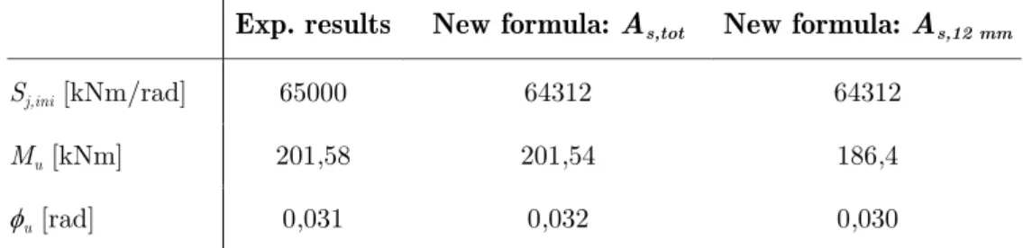
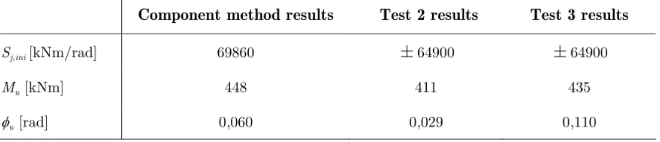
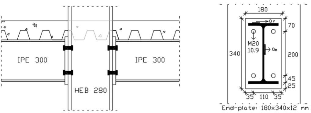
(10) II.3.2.3. “Robustness” project .................................................................................................. II.29 A. Description of the tested joint configuration ................................................................... II.29 B. Experimental results – TEST 1 (hogging moment) ......................................................... II.31 C. Experimental results – TEST 4 (sagging moment).......................................................... II.32 II.3.2.4. “Precious” project....................................................................................................... II.33 A. Description of the tested joint configuration ................................................................... II.33 B. Experimental results – TEST 1 (hogging moment) ......................................................... II.34 C. Experimental results – TEST 2 & 3 (sagging moment)................................................... II.36 II.3.3. Analytical prediction of the composite beam-to-column joint response .............................. II.38 II.3.3.1. Introduction ................................................................................................................ II.38 II.3.3.2. Brief description of the component method................................................................ II.38 A. General principles............................................................................................................ II.38 B. Joint classification ........................................................................................................... II.41 C. Joint modelling and idealisation ...................................................................................... II.41 II.3.3.3. Composite joints subjected to hogging moments ....................................................... II.43 A. Introduction ..................................................................................................................... II.43 B. First comparison – TEST 1 of the “sway frames” project ............................................... II.44 C. Second comparison – TEST 1 of the “Precious” project................................................. II.47 D. Third comparison – TEST 1 of the “Robustness” project ............................................... II.49 II.3.3.4. Composite joints subjected to sagging moments ........................................................ II.51 A. Introduction ..................................................................................................................... II.51 B. Proposed method for the characterisation of the new component “Concrete slab in compression” .............................................................................................................................. II.51 C. First comparison – TEST 4 of the “Robustness” project................................................. II.54 D. Second comparison – TEST 2 & 3 of the “Precious” project.......................................... II.56 II.3.4. Conclusions .......................................................................................................................... II.57. II.4.. Description and validation of the numerical tool .................................................... II.58. II.4.1. Introduction .......................................................................................................................... II.58 II.4.2. Brief description of the homemade FEM software FINELG ............................................... II.58 II.4.3. Assumptions relative to the modelling of the composite structures ..................................... II.59 II.4.4. Benchmark study – UK building.......................................................................................... II.61 II.4.4.1. Introduction ................................................................................................................ II.61 II.4.4.2. Obtained results .......................................................................................................... II.63 A. Displacements in the frames............................................................................................ II.64 B. Bending moment diagrams.............................................................................................. II.65 C. Reasons explaining the result differences........................................................................ II.65 II.4.5. Comparison to experimental test results – Bochum test....................................................... II.66 II.4.5.1. Introduction ................................................................................................................ II.66 II.4.5.2. Brief description of the Bochum frame ...................................................................... II.66 II.4.5.3. Test results.................................................................................................................. II.68 A. Isolated joint test results .................................................................................................. II.68 B. Frame test results............................................................................................................. II.70 II.4.5.4. Comparison numerical prediction vs. experimental results ........................................ II.72 II.4.6. Conclusions .......................................................................................................................... II.73. II.5.. Numerical and analytical investigations of actual composite sway frames........... II.73. II.5.1. Introduction .......................................................................................................................... II.73 II.5.2. Numerical investigations of actual composite sway frames................................................. II.74 II.5.3. Applicability of simplified analytical methods .................................................................... II.77 II.5.3.1. Introduction ................................................................................................................ II.77 II.5.3.2. Amplified sway moment method (“ASMM”) ............................................................ II.78 II.5.3.3. Merchant-Rankine approach (“MR”) ......................................................................... II.81 II.5.3.4. Conclusions ................................................................................................................ II.86. II.6.. Development of a simplified design method for steel and composite sway frames II.87. II.6.1. Introduction .......................................................................................................................... II.87 II.6.2. Parametrical study on steel sway frames.............................................................................. II.90 II.6.2.1. Introduction ................................................................................................................ II.90 II.6.2.2. Parametrical study results ........................................................................................... II.93. 4.
(11) II.6.2.3. Conclusions.................................................................................................................II.96 II.6.3. Parametrical study on composite sway frames .....................................................................II.97 II.6.3.1. Introduction.................................................................................................................II.97 II.6.3.2. Parametrical study results .........................................................................................II.100 II.6.3.3. Conclusions...............................................................................................................II.104 II.6.4. Application of the new method to the actual frames investigated in § II.5.........................II.104 II.6.5. Conclusions ........................................................................................................................II.105. II.7.. Part II conclusions.................................................................................................... II.105. III. Development of membrane effects in steel and composite beams further to an exceptional action ........................................................................................................... III.1 III.1.. Introduction ...........................................................................................................III.3. III.2.. State-of-the-art knowledge on buildings subjected to exceptional events ........III.4. III.2.1. III.2.2. III.2.3. III.2.3.1. III.2.3.2. III.2.3.3. III.2.3.4. III.2.3.5. III.2.3.6. III.2.3.7. III.2.3.8. III.2.4. III.2.5.. Introduction...................................................................................................................... III.4 Important definitions........................................................................................................ III.5 Codes and Standards........................................................................................................ III.6 Introduction................................................................................................................. III.6 British Standards ([52] and [48]) ................................................................................ III.7 Eurocodes [46] ............................................................................................................ III.8 United State General Services Administration guidelines [49]................................... III.9 Unified Facilities Criteria (UFC) of the United State Department of Defence [50].. III.10 United States Civilian Standards [57] ....................................................................... III.11 Canadian code ........................................................................................................... III.11 Conclusions............................................................................................................... III.11 Recent researches........................................................................................................... III.12 Conclusions.................................................................................................................... III.14. III.3. Definition of the general concept adopted for the investigation of the exceptional event “loss of a column in a steel or composite frame”......................................................III.16 III.3.1. Introduction.................................................................................................................... III.16 III.3.2. Description of the adopted general concept ................................................................... III.17 III.3.2.1. Definitions, main assumptions and objectives .......................................................... III.17 III.3.2.2. Loss of a column in a structure ................................................................................. III.19 III.3.3. Adopted strategy within the thesis ................................................................................. III.20. III.4.. Experimental test simulating the loss of a column in a composite frame.......III.24. III.4.1. III.4.2. III.4.2.1. III.4.2.2. III.4.2.3. A. B. C. III.4.2.4. III.4.2.5. III.4.3. III.4.3.1. III.4.3.2. III.4.3.3. III.4.3.4. III.4.3.5. III.4.3.6. III.4.4. III.4.4.1. III.4.4.2.. Introduction.................................................................................................................... III.24 Design of an “actual” composite building according to Eurocode 4 recommendations III.24 Introduction............................................................................................................... III.24 Design of the structural members.............................................................................. III.25 Design of the structural joints subjected to hogging bending moments.................... III.27 Design of the external steel joints .................................................................................. III.27 Design of the internal composite joints.......................................................................... III.28 Conclusions.................................................................................................................... III.29 Verification of the internal main frame modelled with the predicted joint properties III.30 Conclusions............................................................................................................... III.32 Extracted substructure tested at Liège University.......................................................... III.32 Introduction............................................................................................................... III.32 Substructure geometric layout................................................................................... III.32 Reinforcement and stud layouts of the substructure.................................................. III.33 Joint and column base configurations within the substructure.................................. III.34 Simulation of the lateral restraint during the test ...................................................... III.35 Conclusions............................................................................................................... III.36 Performed substructure test............................................................................................ III.36 Introduction............................................................................................................... III.36 Characterization of the constitutive materials ........................................................... III.37. 5.
(12) A. B. III.4.4.3. III.4.4.4. A. B. III.4.4.5. A. B. C. III.4.4.6. III.4.5.. Member steel ..................................................................................................................III.37 Slab concrete (C25/30 concrete).....................................................................................III.37 Geometrical measurements........................................................................................III.38 Description of the loading sequence followed during the test ...................................III.38 Introduction ....................................................................................................................III.38 Loading sequence ...........................................................................................................III.39 Test equipment ..........................................................................................................III.40 Hydraulic jacks (controlled displacement) .....................................................................III.40 Displacement and rotational transducers ........................................................................III.41 Strain gauges ..................................................................................................................III.42 Substructure test results .............................................................................................III.43 Conclusions ....................................................................................................................III.53. III.5. Behaviour of composite joints subjected to combined bending moments and normal forces .........................................................................................................................III.54 III.5.1. Introduction ....................................................................................................................III.54 III.5.2. Experimental tests ..........................................................................................................III.54 III.5.2.1. Introduction ...............................................................................................................III.54 III.5.2.2. Description of the test setup.......................................................................................III.55 III.5.2.3. Test results.................................................................................................................III.57 A. Tested specimen subjected to combined hogging bending moments and normal forces – TEST 1, TEST 2 and TEST 3....................................................................................................III.57 B. Tested specimen subjected to combined sagging bending moments and normal forces – TEST 4 and TEST 5 ..................................................................................................................III.60 C. Conclusions ....................................................................................................................III.61 III.5.3. Development and validation of an analytical procedure to predict the resistance of composite joints subjected to M-N.....................................................................................................III.62 III.5.3.1. Introduction ...............................................................................................................III.62 III.5.3.2. Brief description of the available analytical procedure for steel joints [72] ..............III.63 A. Introduction ....................................................................................................................III.63 B. General concept..............................................................................................................III.63 C. Conventions....................................................................................................................III.65 D. Equilibrium equations for the connection and load eccentricity.....................................III.65 E. Resistance criteria...........................................................................................................III.66 F. Definition of the failure criterion for the whole connection ...........................................III.66 G. Conclusions ....................................................................................................................III.68 III.5.3.3. Extension and validation of the analytical procedure to composite joints .................III.69 A. Introduction ....................................................................................................................III.69 B. Extension of the analytical procedure to composite joints .............................................III.69 C. Validation of the proposed analytical procedure ............................................................III.70 D. Conclusions ....................................................................................................................III.72 III.5.4. Conclusions ....................................................................................................................III.73. III.6.. Validation of the numerical tool.........................................................................III.73. III.6.1. III.6.2. III.6.2.1. III.6.2.2. III.6.2.3. III.6.3. III.6.3.1. III.6.3.2. III.6.3.3. III.6.4.. III.7.. Introduction ....................................................................................................................III.73 Numerical simulation of the substructure test ................................................................III.74 Introduction ...............................................................................................................III.74 Description of the numerical model...........................................................................III.74 Comparison numerical predictions vs. experimental results......................................III.76 Benchmark study............................................................................................................III.77 Introduction ...............................................................................................................III.77 Description of the investigated frame ........................................................................III.77 Comparison of the numerical predictions obtained through different FE software ...III.78 Conclusions ....................................................................................................................III.79. From the actual frame to a simplified substructure modelling .......................III.80. III.7.1. Introduction ....................................................................................................................III.80 III.7.2. Validation of the “simplified substructure approach” ....................................................III.81 III.7.3. Definition of the simplified substructure properties .......................................................III.84 III.7.3.1. Introduction ...............................................................................................................III.84 III.7.3.2. Estimation of K..........................................................................................................III.84. 6.
(13) III.7.3.3. Estimation of FRd ....................................................................................................... III.84 III.7.4. Conclusions.................................................................................................................... III.85. III.8. Analytical method to predict the simplified substructure response with account of the development of the membrane forces .......................................................................III.86 III.8.1. III.8.2. III.8.2.1. III.8.2.2. III.8.2.3. III.8.3. III.8.3.1. III.8.3.2. III.8.3.3. III.8.4.. III.9.. IV.. Introduction.................................................................................................................... III.86 Identification of the parameters to be considered .......................................................... III.86 Introduction............................................................................................................... III.86 Parametrical studies .................................................................................................. III.87 Conclusion ................................................................................................................ III.91 Development of an analytical method ........................................................................... III.92 Introduction............................................................................................................... III.92 Developed analytical method.................................................................................... III.93 Validation through comparisons to the substructure experimental test results ......... III.95 Conclusions.................................................................................................................... III.97. Part III conclusions .............................................................................................III.98. General conclusions, perspectives and personal contributions ..........................IV.1. IV.1.. General conclusions...............................................................................................IV.3. IV.1.1. Main achievements related to the behaviour of composite sway frames subjected to “conventional” loading ........................................................................................................................ IV.3 IV.1.2. Main achievements related to the development of membrane effects in structural steel or composite beams further to a column loss........................................................................................... IV.6. IV.2.. Perspectives ............................................................................................................IV.8. IV.3.. Personal contributions ........................................................................................IV.11. V.. References .............................................................................................................. V.1. VI.. Appendixes ............................................................................................................VI.1. VI.1. Actual properties of the materials used for the experimental tests presented in the thesis VI.3 VI.1.1. Material properties – “Sway frames” project – Isolated single-sided composite joint test and Bochum frame test ........................................................................................................................ VI.3 VI.1.2. Material properties – “Robustness” project – Isolated double-sided composite joint tests and substructure test ............................................................................................................................ VI.4 VI.1.2.1. Introduction................................................................................................................. VI.4 VI.1.2.2. Material properties ...................................................................................................... VI.4 VI.1.3. Material properties – “Precious” project – Isolated single-sided composite joint tests ... VI.5. VI.2. Exploitation of the apparatus measurements obtained for the experimental test performed at Liège University on isolated single-sided composite joints...........................VI.6 VI.2.1. VI.2.2. VI.2.3. VI.2.4.. VI.3. II.4.4) VI.3.1. VI.3.2. VI.3.3.. VI.4.. Introduction...................................................................................................................... VI.6 Computation of the bending moment applied at the joint................................................ VI.7 Rotational transducer measurements ............................................................................... VI.7 Translational transducer measurements ........................................................................... VI.7. Additional results for the benchmark study performed on the “UK” building (§ VI.10 Frame A ......................................................................................................................... VI.10 Frame B ......................................................................................................................... VI.11 Bending moment diagrams at collapse .......................................................................... VI.12. Investigated actual buildings ..............................................................................VI.13 7.
(14) VI.4.1. VI.4.2. VI.4.3. VI.4.4. VI.4.5. VI.4.6. VI.4.7.. Introduction ....................................................................................................................VI.13 “Ispra” building ..............................................................................................................VI.13 “Bochum” building.........................................................................................................VI.15 “UK” building ................................................................................................................VI.15 “Eisenach” building........................................................................................................VI.16 “Luxembourg” building..................................................................................................VI.17 Conclusions ....................................................................................................................VI.18. VI.5. Example of frame investigation in the framework of the parametrical study presented in § II.6.2...............................................................................................................VI.18 VI.5.1. VI.5.2. VI.5.3. VI.5.4.. Investigated frame ..........................................................................................................VI.18 Numerical results............................................................................................................VI.19 Analytical prediction of the ultimate load factor λu........................................................VI.20 Conclusions ....................................................................................................................VI.22. VI.6. Actual dimensions of the substructure (measured at the Argenco laboratory – Liège University)....................................................................................................................VI.22 VI.7. Analytical prediction of the M-N resistance interaction curve of the substructure joint configuration.................................................................................................................VI.26 VI.7.1. VI.7.2. VI.7.3. VI.7.3.1. VI.7.3.2. A. B. C. D. VI.7.3.3. A. B. C. VI.7.3.4.. Introduction ....................................................................................................................VI.26 Studied composite joint configuration............................................................................VI.27 Computation of the M-N resistance interaction curve....................................................VI.30 Introduction ...............................................................................................................VI.30 Upper rows in tension ( Fi Rd ,+ )..................................................................................VI.30 Point A: all the rows are in tension.................................................................................VI.30 Point B: rows 1 to 10 in tension and row 11 in compression .........................................VI.30 Point C: rows 1 to 9 in tension and rows 10 and 11 in compression ..............................VI.30 Point D: rows 1 to 8 in tension and rows 9 to 11 in compression...................................VI.30 Lower rows in tension ( Fi Rd ,− ) .................................................................................VI.31 Point E: all the rows are in tension .................................................................................VI.31 Zone F: rows 2 to 11 in tension and row 1 in compression ............................................VI.31 Zone G: rows 4 to 11 in tension and row 1 to 3 in compression ....................................VI.31 Obtained M-N resistance interaction curves..............................................................VI.31. VI.8. Details of computation relative to the developed analytical method to predict the development of the membrane forces in the simplified substructure and their effect in the substructure response ...........................................................................................................VI.32 VI.8.1. VI.8.2. VI.8.3.. Introduction ....................................................................................................................VI.32 Analytical procedure with account of p..........................................................................VI.34 Analytical procedure without account of p.....................................................................VI.37. List of Figures List of Tables. 8.
(15) Acknowledgements. The present thesis is the result of six years of research at Liège University and is the fruit of kind collaborations. Within the present acknowledgement, I would like to express my gratitude to different persons who significantly contributed to the achievement of the present work. I would like to thank first Prof. Jean-Pierre Jaspart, the promoter of the thesis, for his support and his advices. During this six year period, he created the best conditions to make possible the achievement of this work, offering me the possibility to participate actively to European projects and actions. My gratitude goes also to Prof. Maquoi for his encouragements and all the interesting discussions we had, in particular on the rules of Eurocode 4. Then, my acknowledgments go to the technical staff of the Argenco laboratory and in particular, to Carl Vroomen and Etienne Rondia who contributed actively to the success of the experimental tests I had the opportunity to realise within the present work. I would like also to thank my “office” colleague, Dr. Lam Ly with whom I have the chance to collaborate since my arrival at University, for his help and for all the interesting discussions we had. Now, I will switch to French to thank my friends and my family. Je tiens à remercier mes amis et ma famille et en particulier, mes parents, pour toutes les marques de soutien qu’ils ont manifesté. Je terminerai en remerciant mon épouse, Valérie, pour son soutien permanent et ma petite Nora qui, dès ses premiers jours, a dû supporter les absences répétées de son papa.. 9.
(16)
(17) Notations Latin letters: A. : total area of a cross section. AIPE200. : cross section area of an IPE200 profile. As. : steel rebars area of a concrete or composite slab. As,2. : total area of the transverse slab rebars behind the column in the vicinity of an external composite joint. ASMM. : amplified sway moment method. Aw. : area of the web of a double T cross section. b. : width of the flanges of a double T cross section. bc. : width of a column profile flange. beff. : effective width of a composite slab. beff,conn. : effective width of the concrete/composite slab contributing to the composite joint resistance subjected to sagging moments. DL. : dead loads. E. : Young elastic modulus. Ea. : Young elastic modulus for the steel material. Ec or Ecm : secant Young modulus for the concrete. εu,average. : average ultimate strain of a material. fck. : characteristic resistance stress for the concrete. fck,actual. : actual resistance stress for the concrete obtained through cylinder tests. fck,column. : characteristic resistance stress for the concrete of a composite column. fck,slab. : characteristic resistance stress for the concrete of a composite or reinforced concrete slab. FE. : Finite Elements. FEM. : Finite Element Method. Fi. : load in row i within a connection. 11.
(18) FRd. : resistance of the indirectly affected part subjected to horizontal loads. FRd,i. : design resistance load of the component i. fsk. : characteristic resistance stress for steel rebars. fu. : ultimate stress of a material. fu,average. : average value of a ultimate stress. fu,flange. : ultimate stress of the flanges of a double T cross section. fu,long.. : longitudinal ultimate stress of a plate (according to the rolling process). fu,trans.. : transversal ultimate stress of a plate (according to the rolling process). fu,web. : ultimate stress of the web of a double T cross section. fy. : yielding stress of a material. fy,average. : average value of a yielding stress. fy,flange. : yielding stress of the flanges of a double T cross section. fyk. : characteristic yielding stress of a material. fy,long.. : longitudinal yielding stress of a plate (according to the rolling process). fy,overstrength : yielding stress affected by an overstrength coefficient fy,trans.. : transversal yielding stress of a plate (according to the rolling process). fy,web. : yielding stress of the web of a double T cross section. h. : height of a storey, of a column or of an element cross section. hc. : height of a column profile cross section. hconcrete. : total height of a concrete slab. HEd,i. : design value of the horizontal reaction at the bottom of storey i. hi. : height of storey i or position of row according to the beam reference point within a connection. hstruc. : total height of a structure. I or Ib. : moment of inertia of a beam according to the major axis. IIPE200. : moment of inertia of an IPE200 profile according to the major axis. K. : lateral restraint coming from the indirectly affected part of a structure losing a column. 12.
(19) kcsc. : stiffness of the component “concrete slab in compression”. ki. : stiffness of the component i. L. : span or length of a beam. LL. : live loads. m. : number of columns in a row. M. : bending moment. Me. : elastic resistance to bending moments of a joint. MEd. : design applied moment on an element or a joint. MMR. : modified Merchant-Rankine. MN,Rd. : design resistance to bending moments of a cross section associated to NEd. Mpl,Rd. : design plastic resistance to bending moments of a structural element. MR. : Merchant-Rankine. MRd. : design resistance to bending moments of a joint. MRd1. : resistance to bending moments of the plastic hinges 1 and 4 in the simplified substructure modelling associated to the axial resistance NRd1. MRd2. : resistance to bending moments of the plastic hinges 2 and 3 in the simplified substructure modelling associated to the axial resistance NRd2. Mu. : ultimate resistance to bending moments of a joint. n. : total number of storeys in a structure or of rows within a connection. N. : axial load. Nb. : number of bolt rows within a connection. NEd. : design normal applied load. Nlo. : axial load in a loss column. Npl,Rd. : plastic resistance to normal forces of a cross section. NRd1. : resistance to normal forces of the plastic hinges 1 and 4 in the simplified substructure modelling associated to the resistance in bending MRd1. NRd2. : resistance to normal forces of the plastic hinges 2 and 3 in the simplified substructure modelling associated to the resistance in bending MRd2. Nup. : axial load in the column just above a loss column 13.
(20) p. : uniformly distributed load applied to the simplified substructure. Q. : concentrated load to be support by the simplified substructure. Sj,ini. : initial stiffness of a joint. Sj,post-limit. : post-limit stiffness of a joint. SLS. : serviceability limit states. tf. : thickness of a profile flange. ULS. : ultimate limit states. V1 and V2 : shear loads at the extremities of the left and right beams connected at the top of the loss column Vcr. : critical vertical load of a structure associated to a global sway mode of instability. VEd. : total vertical load applied to a structure. VEd,i. : design vertical load on the structure at the bottom of storey i. VRd. : design resistance to shear forces of a joint. z. : height of the concrete/composite slab contributing to the composite joint resistance subjected to sagging moments. Greek letters: αh. : reduction factor for height h applicable to columns. αm. : reduction factor for the number of columns in a row. β. : transformation parameter for the column web panel in shear in a joint. χ. : reduction factor used in the Ayrton-Perry formulation. χbeam. : reduction factor associated to a beam plastic mechanism in the developed new method. χcombined. : reduction factor associated to a combined plastic mechanism in the developed new method. χpanel. : reduction factor associated to a panel plastic mechanism in the developed new method. 14.
(21) Δ. : horizontal displacement at the top of a structure. Δa. : vertical displacement of the top of the loss column. δH,Ed,i. : horizontal displacement at the top of storey i, relative to the bottom of storey i, when the frame is loaded with horizontal loads which are applied at each floor level. δK. : elongation of the horizontal spring simulating the lateral restraint coming from the indirectly affected part in the simplified substructure. δN1. : elongation of the plastic hinges 1 and 4 in the simplified substructure. δN2. : elongation of the plastic hinges 2 and 3 in the simplified substructure. εcu. : ultimate deformation which can be reached in the concrete in compression. φ. : rotation of a joint. Φ0. : basic value for global initial sway imperfection. Φini. : global initial sway imperfection. φu. : rotation associated to the ultimate bending moment Mu of a joint. γ. : rotation associated to a column web panel in shear. γc. : safety coefficient associated to the concrete material. γs. : safety coefficient associated to the steel rebar material. ϕ. : rotation associated to a connection within a joint. λ. : non dimensional relative slenderness. λ0. : length of the plateau in a χ - λ graph. λbeam. : non dimensional relative slenderness associated to a beam plastic mechanism in the developed new method. λcombined. : non dimensional relative slenderness associated to a combined plastic mechanism in the developed new method. λpanel. : non dimensional relative slenderness associated to a panel plastic mechanism in the developed new method. λcr. : critical load factor (= Vcr/VEd). λcr,cracked : critical load factor of a composite structure with the concrete assumed to be cracked in the hogging moment zone. 15.
(22) λcr,uncracked : critical load factor of a composite structure with the concrete assumed to be uncracked. λEd. : design load factor associated to the applied load. λp. : load factor associated to the collapse mode obtained through a first order rigidplastic analysis. λp,beam. : plastic load factor associated to the development of a beam plastic mechanism. λp,combined : plastic load factor associated to the development of a combined plastic mechanism. λp,panel. : plastic load factor associated to the development of a panel plastic mechanism. λu. : load factor associated to the collapse mode obtained through a fully non-linear analysis. λu,beam. : ultimate load factor obtained through the developed new method and associated to the beam plastic load factor. λu,combined : ultimate load factor obtained through the developed new method and associated to the combined plastic load factor. λu,panel. : ultimate load factor obtained through the developed new method and associated to the panel plastic load factor. μ. : parameter influencing the shape of the curve obtained through the AyrtonPerry formulation. μbeam. : value of μ associated to a beam plastic mechanism in the developed new method. μcombined. : value of μ associated to a combined plastic mechanism in the developed new method. μpanel. : value of μ associated to a panel plastic mechanism in the developed new method. θ. : rotation of the plastic hinges at the simplified substructure extremities. σ. : axial stress. τ. : shear stress. Ψ. : parameter influencing the shape of the non-linear part of a moment-rotation curve of a joint. Ψbraced. : lateral flexibility of the structure with the bracing system 16.
(23) Ψunbraced. : lateral flexibility of the structure without the bracing system. 17.
(24)
(25) Summary The present thesis is dedicated to the study of the behaviour of steel and composite steelconcrete building frames with a particular attention paid to the beam-to-column joint behaviour. Two main topics are investigated herein: -. the behaviour of sway building frames subjected to “conventional” loadings and;. -. the development of the membrane forces in structural beams further to the loss of a column.. Regarding the first topic, the main objective is to propose a simplified analytical method to predict the ultimate load factor of composite sway building frames, a case not yet covered by the actual codes and standards. To achieve this goal, the behaviour of composite joints subjected to bending moments is first studied through experimental and analytical investigations; indeed, the joints are key elements influencing the response of sway frames. Through these investigations, a new collapse mode is identified for single-sided composite joints subjected to hogging moments and an analytical method is proposed and validated to introduce this new collapse mode in the joint design. In addition, an analytical method is also proposed and validated to predict the response of composite joints subjected to sagging moment, a situation which can occur in composite sway frames subjected to horizontal loads but not yet covered by the actual codes. Afterwards, the numerical tool used to predict the response of composite sway frames is validated through a benchmark study and through comparisons with experimental test results coming from two tests performed in European laboratories. With the so-validated software, the behaviour of actual sway building frames (i.e. frames extracted from existing buildings) is investigated, highlighting their particularities. The applicability to composite sway frames of two simplified analytical method initially developed for steel sway frames (an elastic one called the “amplified sway moment method” and a plastic one called the “Merchant-Rankine approach”) is then studied. From these investigations, it is demonstrated that the elastic method can be applied with good confidence to composite sway frames while the plastic one illustrates the same problems of accuracy already observed in previous studies on steel sway frames; in particular, the plastic method may prove to be very unsafe if the collapse mode associated to the ultimate limit state is a panel plastic mechanism.. 19.
(26) Finally, according to these results, a simplified analytical method is developed for the prediction of the ultimate load factor of steel and composite sway frames. The proposed method is founded on the Ayrton-Perry formulation and is validated through comparison to results obtained with full non-linear numerical analyses performed on more than 300 steel and composite frames. The so-validated method is easy to apply and permits to predict with a very good accuracy the ultimate load factor of a sway frame and the collapse mode appearing at the ultimate limit state. Founded on the knowledge gained from the previous topic on the structural behaviour of steel and composite structures, the behaviour of such structures subjected to an exceptional event is investigated within the second topic. The main objective is to propose a simplified analytical procedure to predict the development of the membrane forces within a structure further to the loss of a column and their effects on the structural response. In a first step, a general procedure allowing the prediction of the response of a structure further to the loss of a column is first defined, with a particular attention paid to the influence of the development of the catenary action on this response. Then, an experimental test performed at Liège University and simulating the loss of a column in a composite frame is described. The objective of this test is to observe the development of the catenary action within the tested structure and its effect on the joint behaviour. The described test constitutes a European first in this domain. Also, as for the previous topic, the behaviour of joints is investigated in details. Here, the particularity is the fact that the joints are subjected to combined bending moments and axial loads when the membrane effects developed in the structure. In a previous PhD thesis presented at Liège University, an analytical procedure founded on the component method was developed to predict the response of steel joints subjected to such loading. Within the present thesis, this method is extended to composite joints and validated through comparisons to experimental tests. Afterwards, the numerical tool used for the numerical investigations is validated through a benchmark study and through comparisons with the results of the experimental test performed at Liège University. In particular, the difficulty of simulating the actual behaviour of beam-to-column joints subjected to combined bending moments and axial loads is illustrated. With the so-validated software, a simplified substructure modelling, on which the developed analytical method is founded, is then validated. In addition, parametric. 20.
(27) numerical studies are performed on the substructure modelling in order to identify the parameters to be considered within the developed method. Finally, the developed simplified analytical method is described and validated through comparisons between the experimental results and the analytical prediction. With this “easy-to-apply” method, a very good accuracy is achieved; in particular, it is possible to predict the requested deformation capacity in the structural elements where plastic hinges are developed and the membrane forces which have to be supported by the structure.. 21.
(28)
(29) Résumé La présente thèse est dédiée à l’étude du comportement des portiques de bâtiments en acier et mixte acier-béton avec une attention particulière portée sur le comportement des assemblages poutre-colonne. Deux sujets principaux sont abordés : -. l’étude du comportement des portiques à nœuds transversalement déplaçables soumis à un chargement “classique” et ;. -. l’étude du développement des efforts membranaires dans les poutres d’un portique suite à la perte d’une colonne.. Concernant le premier sujet, l’objectif principal est de proposer une méthode analytique simplifiée permettant de prédire le multiplicateur de charge ultime de portiques mixtes à nœuds transversalement déplaçables, cas non encore couvert par les codes actuels. Pour atteindre cet objectif, le comportement des assemblages mixtes soumis à des moments de flexion est étudié dans un premier temps aux travers d’études expérimentales et analytiques, les assemblages étant des éléments clés dans l’étude du comportement des portiques à nœuds transversalement déplaçables. Via ces études, un nouveau mode de ruine est mis en évidence pour les assemblages mixtes externes et une méthode analytique est proposée et validée pour la prise en compte de ce nouveau mode de ruine dans le dimensionnement de ces assemblages. De plus, une méthode analytique est également proposée et validée pour prédire la réponse des assemblages mixtes soumis à moment positif, situation pouvant apparaître dans les portiques mixtes à nœuds transversalement déplaçables soumis à un chargement horizontal mais non encore couverte par les codes actuels. Ensuite, l’outil numérique utilisé pour prédire la réponse des portiques est validé par une étude comparative réalisée avec différents logiciels et par une comparaison à des résultats expérimentaux provenant de deux essais réalisés dans des laboratoires Européens. Avec cet outil ainsi validé, le comportement de portiques mixtes réels (c’est-à-dire extraits de bâtiments existants) est étudié en mettant en évidence leurs particularités. L’applicabilité à des structures mixtes de deux méthodes simplifiées initialement développées pour des portiques en acier à nœuds transversalement déplaçables (une élastique intitulée “amplified sway moment method” et une plastique intitulée “approche de Merchant-Rankine”) est alors étudiée. Suite à cette étude, il est démontré que la méthode élastique peut être assurément appliquée aux portiques mixtes tandis que la méthode plastique démontre les mêmes problèmes de précision que ceux déjà observés dans des études précédentes réalisées sur des portiques en acier ; en particulier, la méthode 23.
(30) peut se révéler être très insécuritaire si le mécanisme de ruine associé à l’état limite ultime est un mécanisme plastique de panneau. Finalement, suite à cette dernière observation, une méthode analytique simplifiée est développée pour la prédiction du multiplicateur de charge ultime de portiques mixtes et en acier à nœuds transversalement déplaçables. La méthode proposée est fondée sur la formulation d’Ayrton-Perry et est validée par des comparaisons à des résultats obtenus via des analyses non-linéaires réalisées sur plus de 300 portiques en acier et mixtes. La méthode ainsi validée est facile à utiliser et permet d’obtenir le multiplicateur de ruine d’un portique avec une très bonne précision ainsi que le mode de ruine apparaissant à l’état limite ultime. Suite à l’expérience acquise sur le comportement des structures en acier et mixtes soumises à un chargement « classique », le comportement de celles-ci soumises à une action exceptionnelle a alors été étudié. L’objectif principal est la proposition d’une méthode analytique simplifiée permettant de prédire le développement des forces membranaires dans une structure suite à la perte d’une colonne et leurs effets sur la réponse structurale. Dans un premier temps, une procédure générale permettant de prédire la réponse d’une structure lors de la perte d’une colonne est définie, mettant en évidence l’influence du développement des efforts membranaire sur cette réponse. Un essai expérimental réalisé à l’Université de Liège et simulant la perte d’une colonne dans un portique mixte est ensuite présenté. L’objectif de cet essai est d’observer le développement des efforts membranaires dans la structure testée et leurs effets sur le comportement des assemblages. L’essai présenté constitue une première Européenne dans ce domaine. Comme pour le sujet précédent, le comportement des assemblages est aussi étudié en détail. Ici, la particularité est le fait que les assemblages sont soumis à la fois à des moments de flexion et à des efforts axiaux lorsque les effets membranaires se développent dans la structure. Dans une thèse de doctorat précédente présentée à l’Université de Liège, une procédure analytique fondée sur la méthode des composantes a été développée pour prédire la réponse d’assemblages en acier soumis à un tel chargement. Dans la présente thèse, cette méthode est étendue au cas des assemblages mixtes et validées via des comparaisons à des résultats expérimentaux. Ensuite, l’outil numérique utilisé est validé par une étude comparative réalisée avec différents logiciels et par des comparaisons aux résultats de l’essai réalisé à l’Université de Liège. En particulier, la difficulté de simuler le comportement réel d’assemblages soumis à une action combinée d’efforts de flexion et d’efforts axiaux est illustrée. 24.
(31) Avec le logiciel ainsi validé, un modèle simplifié de sous-structure permettant de développer la méthode analytique simplifiée est défini et validé via des études numériques. De plus, des études paramétriques sont réalisées sur ce modèle afin d’identifier les paramètres à prendre en compte dans la méthode développée. Finalement, la méthode simplifiée développée est décrite et validée via des comparaisons entre les résultats expérimentaux et les prédictions analytiques. Avec cette méthode facile à utiliser, une très bonne précision est obtenue ; en particulier, il est possible de prédire la demande en terme de capacité de déformation au niveau des éléments structuraux où se forment des rotules plastiques et de déterminer les efforts membranaires devant être supportés par la structure.. 25.
(32)
(33) I. General introduction. I. General introduction. I.1.
(34)
(35) I.1.. Generalities. Since long time, the behaviour of steel and steel-concrete composite building frames has been the topic of a lot of researches worldwide; the results of these researches had significant impacts in the understanding of their behaviour, in the development of design procedures for such frames and, also, in the development of the associated codes and standards. In particular, in the last decade, the M&S department of Liège University (department which is now integrated in a bigger department called Argenco) had the opportunity to participate to European projects dedicated to the behaviour of steel-concrete composite sway building frames and to the behaviour of steel and composite buildings (or of their structural elements) subjected to exceptional actions; these projects are summarised here below: -. An ECSC (European Coal and Steel Community) project titled “Applicability of composite structures to sway frames” (contract N° 7210-PR-250 – acronym: Sway frame) [1]: the objective of this project was to provide background information on the behaviour of composite framework structures under monotonous and cyclic loads. Particular attention was paid to the sway behaviour and to the beam-tocolumn joint behaviour. In particular, limitations or particular provisions for such structures for both the serviceability and ultimate limit state were provided.. -. An ECOLEADER project titled “3-D full scale seismic testing of a steel-concrete composite building at ELSA” (EUR 21299 EN) [2]: this project was dedicated to the performance of an experimental test to investigate the behaviour of a high ductile steel-concrete composite frame structure characterized by partially encased columns and dissipative partial strength joints, where both the column web panel, not surrounded by concrete, and the beam-to-column connection share the energy dissipation demands. The performed test allows promoting the development of design rules currently not covered by Eurocode 8.. -. An RFCS. (Research Fund for Coal and Steel) project titled “Prefabricated. composite beam-to-concrete filled tube or partially reinforced-concrete-encased column connections for severe seismic and fire loadings” (Project N° RFS-PR02002 – acronym: Precious) [3]: this research programme intended to develop fundamental data, design procedures and promotion of two types of ductile and fire-resistant composite beam-to-column joints with: partially reinforced-concreteencased column with I-section and concrete filled tubular column with circular hollow steel section.. I. General introduction. I.3.
(36) -. An RFCS project titled “Robust structures by joint ductility” (Project N° RFSCR-04046 – acronym: Robustness) [4]: robustness ensures structural safety by preventing the collapse of the total structure when only one part of the structure is damaged or destroyed. By intelligent design the possibility of force redistribution is given after extensive plastification of joints and single structural elements. Thus the structure keeps its strength even under exceptional loading and under large deformations. Profiting from the inherent ductile behaviour of steel, this project analysed the requirements for robustness and developed new ductile joint solutions to allow for this force redistribution. Criteria for robust structures, especially concerning steel and composite joints were elaborated and illustrated by drawings in a handbook for an easy understanding and realisation by the constructor.. The present thesis reflects activities which were initiated in 2001. Part of the developments presented herein is directly linked to the activities of the department within these European projects. In particular, two investigated topics are addressed: -. the behaviour of steel-concrete composite building frames subjected to significant second-order effects when subjected to “conventional” loading and;. -. the development of membrane effects in structural steel or composite beams further to an exceptional event.. For each topic, the performed investigations include experimental, numerical and analytical aspects. The plan of the thesis is detailed in the following paragraph.. I.2.. General plan of the thesis. The present thesis is divided in six main parts (divided in paragraphs, themselves divided in sections). The first one is the present one and contains the general introduction of the thesis. The second one is dedicated to the study of the behaviour of steel-concrete composite sway frames subjected to “conventional” loading. The main objective of this study is to propose simplified analytical methods to predict the response of these frames. Within the study, a particular attention is paid to the behaviour of the beam-to-column composite joints as the latter are key elements influencing significantly the global sway frame behaviour. Also, the behaviour of actual composite building frames, i.e. frames extracted from “real” buildings, is numerically and analytically investigated. At the end, an analytical method, founded on the Ayrton-Perry formulation and applicable to steel and composite sway frames, is developed and validated to predict the ultimate load factor of. I. General introduction. I.4.
(37) these frames with a very good accuracy and to predict the collapse mode occurring at the ultimate limit state. Founded on the knowledge gained from the previous part on the structural behaviour of steel and composite structures subjected to significant second order effects, the third part is devoted to the study of such structures subjected to an exceptional event: loss of a column further to an impact. In particular, the development of the membrane effects in steel or composite structural beams associated to the column loss is investigated. The performed developments (including experimental, numerical and analytical approaches) are part of a general concept which is first described. Then, an experimental test simulating the loss of a column in a composite building performed at Liège University is presented; the performed test constitutes a European first. The behaviour of joints subjected to combined bending moments and axial loads (associated to the membrane forces) is also investigated in details through experimental and analytical studies; in particular, an analytical method to predict the response of composite joints subjected to such loadings is proposed and validated. Finally, a simplified analytical method to predict the development of the membrane forces in a steel or composite frame and their influence on the frame response is developed and validated. The fourth part presents the general conclusions of the thesis and perspectives. To ensure a fluidity of the lecture of the previous parts, the personal contributions to the presented developments are not highlighted within the text; however, a paragraph dedicated to these personal contributions is included in the fourth part. Finally, the fifth and the sixth parts are devoted to the references and appendixes respectively. In the appendixes, some additional information concerning the performed experimental tests or the performed computations are given.. I. General introduction. I.5.
(38)
(39) II. Sway response of composite building frames subjected to “conventional” loading. II. Sway response of composite building frames subjected to “conventional” loading. II.1.
(40)
(41) II.1.. Introduction. II.1.1.. Context. Most steel-concrete composite structures are laterally restrained by efficient bracing systems, such as concrete cores. This practice does not favour the use of composite structures. Indeed, once concrete construction companies are involved into major parts of a building, the reason for using composite structures for subsequent parts is often questionable. As an alternative, moment resisting frames, without bracing systems, offer a flexible solution to the user of the buildings, especially for the internal arrangements and the exploitation of the buildings. When sufficient stiffness and strength with regard to lateral forces are achieved, such frames offer a structural solution, which can resist lateral loads. In seismic regions, properly designed moment resisting frames are the best choice regarding the available ductility and the capacity to dissipate energy. This is stated in Eurocode 8 [5] devoted to earthquake engineering in which high values of the behaviour factor are recommended. Obviously, the construction of tall buildings and large industrial halls without wind bracing systems is susceptible to make global instability a relevant failure mode; this is not yet well covered by Eurocode 4 [6] and other references ([7], [8] and [9]) which mainly deals with composite construction under static loading. Indeed, as far as the European codes are concerned, Eurocode 4 contains design procedures for non-sway composite buildings and gives design rules for composite slabs, beams, columns and joints; composite sway frames are allowed in Eurocode 4 but no information on how to design them are given. That is the reason why two European research projects on composite sway frames, in which Liège University was involved, have been conducted recently: -. the first one involving seven institutions and titled “Applicability of composite structures to sway frames” (Contract N° 7210-PR-250) [1] was funded by the European Coal and Steel Community (ECSC) for three years (from July 2000 to June 2003);. -. the second one was an Ecoleader project (from July 2000 to June 2003) titled “3-D full scale seismic testing of a steel-concrete composite building at ELSA” involving six institutions [2].. II. Sway response of composite building frames subjected to “conventional” loading. II.3.
Figure

![Figure II.18. Moment-rotation curve of the joint obtained through TEST 1 [19]](https://thumb-eu.123doks.com/thumbv2/123doknet/6098001.154593/69.892.239.680.784.1042/figure-ii-moment-rotation-curve-joint-obtained-test.webp)
![Figure II.19. Photos of the joint at the end of TEST 4 [19]](https://thumb-eu.123doks.com/thumbv2/123doknet/6098001.154593/70.892.123.761.597.806/figure-ii-photos-joint-end-test.webp)

+7


Documents relatifs
En la Decimocuarta Reunión Ordinaria de la JIA, los representantes de los Estados Miembros del Instituto tomarán decisiones sobre políticas institucionales y sobre
Ce lien entre les TET et OGT suggère que les TET peuvent être impliquées dans l’étiologie de nombreuses mala- dies impliquant des défauts méta- boliques, en particulier le
La pause méridienne est donc un temps où se jouent également beaucoup de choses au niveau du rapport à l’espace pour les élèves : contribue-t-elle, avec son lot de conflits et de
Après avoir exploré la place que souhaite donner l’Education Nationale aux compétences orales mais également le caractère essentiel que celles-ci revêtent pour l’intégration
1 CSTB (France) Centre Scientifique et Technique du Bâtiment, 2 EBF GmbH (Germany) Energy Biosphere Food ; 3 ULg (Belgium) University of Liège, Gembloux Agro-Bio.. Tech & HEC
Experimental measurement of flow distribution in a parallel mini-channel fluidic network using PIV technique... For
Néanmoins, j’ai pu constater que ça marchait quand même pas mal, et dans l’utilisation, pour nous en tous cas, où au quotidien la téléconsultation est pas vraiment quelque chose
Troisième et quatrième volume de cette collection de la plus haute importance pour la docu- mentation ethnographique et sociologique; les peuplades y sont décrites dans
