1 INTRODUCTION 1.1 Objectives
The behaviour of steel and composite frames after failure of local structural elements caused by excep-tional loadings (e.g. failure of a column caused by a vehicle impact, explosion, fire, earth-quake, floods) is investigated. A progressive failure of the whole structure can be prevented by robust design. Robust-ness ensures structural safety by preventing the col-lapse of the total structure when only one part of the structure is damaged or destroyed.
This can be achieved by enabling the joints to provide large rotations, so that membrane forces can be activated allowing a redistribution of internal forces. Thus an adaptive structure is created which keeps sufficient strength even under exceptional loading and large deformations.
By increasing deformations joints are subjected to increased tensile forces, while bending moment ex-posure of the joints decreases or is even inversed. Within the research project various experimental in-vestigations are made on the behaviour of the joints under large deformations and combined loading of bending and tension, including a full scale test of a substructure, joint tests and component tests.
The main objective of the project is to derive and develop simplified and economic design criteria al-lowing the designer to satisfy, in practical situations, the general requirement for robustness.
1.2 Concept
As a general procedure to derive robustness re-quirements, different structural systems subjected to exceptional events are numerically investigated in order to see how the structures work when part of the structure is destroyed as well as how and how far redistribution takes place. Practically speaking, many exceptional events could be considered, but only few are covered by the present project and spe-cial focus is given to:
− loss of a column in an office or residential build-ing frame
− loss of a bracing in a car park
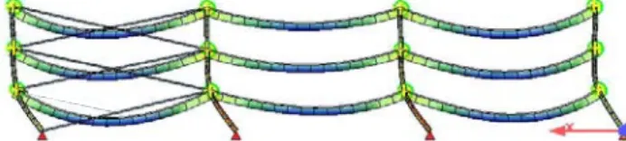
For these cases, FEM numerical simulations (see e.g. Figure 1) are carried out. In this process, a spe-cial attention is devoted to the study of the loading sequence inside the joints. As a result of these FEM numerical simulations and associated parametrical studies, simplified behavioural models will be de-veloped and validated; these should progressively lead to analytical models, from which requirements to be satisfied by the structural system and by the joints will be derived.
Figure 1. Car park frame with loss of a bracing
Robustness – Robust structures by joint ductility
Prof. Dr.-Ing. U. Kuhlmann, L. Rölle
Institute of Structural Design, Universität Stuttgart, Germany
Prof. Dr.-Ing. J.-P. Jaspart, J.-F. Demonceau
MS2F Devision, Département ArGEnCo, Université de Liège, Belgium
ABSTRACT: In view of recent disasters and their immense economical and human consequences more and more focus is given not only on the safety of structures - to reduce the risk for the life of people by collapse even under exceptional loading – but on minimizing the disastrous results and to enable a quick rebuilding and reuse. One crucial mean to achieve this aim is the design of redundant robust structures. Robustness pre-vents the collapse of the total structure when only parts of the structure are damaged or destroyed. To avoid progressive failure, redundant structures with inherent sufficient ductile behaviour allowing deformations when a local failure occurs, have to be built. Redundancy can be achieved by allowing force redistribution within a structural system. Therefore the single sections and joints have to be especially designed and opti-mized, not necessarily requiring additional fabrication costs. But until now no specific rules for robustness by ductile joints exist. The aim of the present project is to define general requirements for ductile joints as part of a structural system subjected to exceptional unforeseen loading.
In Figure 2, the strategy followed is described for the example of the substructure test as performed by the University of Liège. Within this strategy, ex-perimental, numerical and analytical aspects are in-volved. First (step 1), the experimental tests are per-formed. Then, with the obtained results, the numerical FEM tools used within the project are validated (step 2) so as to use it latter on to perform parametrical studies (step 3); the objective of the lat-ters is to identify the paramelat-ters influencing the frame response after the loss of the column or a bracing. In a last step, analytical simplified methods are developed (step 4) with due account taken of the parameters identified in step 3. Finally, design guidelines are derived through step 3 and 4 so as to reach the final objective of the RFCS project.
STEP 1: experimental test on a substructure
simulating the loss of a column
STEP 2: validation of the numerical FEM
tools
STEP 3: parametrical numerical studies
STEP 4: development of simplified analytical methods
Derivation of design guidelines for practitioners
Figure 2. Global strategy followed within this project
2 EXPERIMENTAL WORK
Aside of the numerical investigations a lot of fo-cus is given to the experimental tests which have been performed by three of the partners, in Trento, Stuttgart and Liège. So the adjustment of the various tests was very important (Figure 3).
component tests joint tests substructure test
part of part of
Trento Stuttgart Liège
Figure 3. Experiments form a unique chain.
It was agreed that the experiments should be a unique chain. This means the joints tested in Stutt-gart are part of the substructure test conducted in Liège, as well as the component tests of Trento in-clude all components which are relevant within the joint and substructure tests. Therefore profiles and
plates were used of one rolling. The reinforcement for the testing bodies has been ordered together us-ing reinforcement bars of one rollus-ing for each di-ameter and the same geometry was chosen.
2.1 Joint Tests
2.1.1 General
The joint tests realized at the University of Stuttgart can be subdivided into two main series: One series on composite joints with dimensions and design re-lated to the substructure test in Liège, and a second series bending tests on pure steel joints. The tests on composite joints mainly investigate the behaviour of the joints under combined loading. Special focus is given on the load path.
The aim of the pure steel joint tests on large IPE 500 profiles with thin endplates is to analyse the ductility for steel joints and its main components bolts in tension and endplate in bending. In previous tests conducted in Stuttgart by Kuhlmann/Schäfer brittle failure of the bolts had been observed al-though the ductility criterion according to EN 1993-1-8 was not violated. It is assumed that the brittle bolt failure occurred due to bending exposure of the bolts. This bending exposure seems to depend on the distance between the flange and the web of the beam on one hand side and the bolt on the other side. To receive more reliable criteria these tests with varied endplate thickness and bolt distances were con-ducted. A strong dependency of the failure mode re-sults from the behaviour of the single components. 2.1.2 Composite joint tests
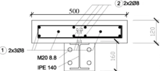
As explained for the substructure test in chapter 2.2 two different situations exist: a hogging bending moment for the first inner joint in Figure 10 which undergoes an increase of the bending moment as well as an additional membrane force action and a sagging moment with a combined tension force at the inner joint where the loss of the column oc-curred. To investigate this five composite joints un-der combined loading have been tested, three joints under negative (hogging) moment and two joints under positive (sagging) moment. The first of each group has been a pure bending test in order to evalu-ate the actual hogging and sagging bending capacity. For the following tests the joints were exposed to a change from pure bending moment to combined bending and tension. The dimensions as well as the used profiles for the joint configuration are given in Figure 4 and follow the chosen sections of the sub-structure test. For both types of composite joint tests, for hogging moment as well as sagging moment tests, special care has been taken of the loading pro-cedure, see Figure 5&6.
500
Figure 4. Cross-section of the composite joints
At the first stage, see Figure 5, by increasing force and deformation by the vertical hydraulic jack a moment just below the ultimate moment of the joint Mj,u was applied to the testing specimens. Then
the vertical jack was arrested in order to keep the ro-tation of the joint as presented in Figure 6. Then by the horizontal hydraulic jack a tensile force was ap-plied on the testing body, leading to a biaxial load-ing of the specimen. The tensile force was increased until collapse of the joint.
Figure 5. First stage of the composite testing procedure
Figure 6. Second stage of the composite testing procedure
The arrangement of the transducers at the composite joints was chosen in order to measure all compo-nents of the joints which contribute to the rotation capacity of the joint and to determine the single load deformation behaviour of the relevant components.
The most important outcome of the joint tests is the moment-rotation curves as well as the M-N-interaction behaviour. Both are needed later to com-pare and calibrate the joint behaviour which is given by the numerical simulations.
2.1.3 Test results of composite joint tests
The progress of the joint behaviour during the tests was as follows: By increasing the bending mo-ment in the test specimen for hogging momo-ment the cracks in the concrete slab developed at the column section. When reaching nearly Mu the slab at the
col-umn section was cracked over the total height. By applying an additional horizontal tensile force the deformations of the slab as well as of the endplate and column flange clearly increased. At the end the
failure mode for all specimens under hogging mo-ment was failure of the reinforcemo-ment bars. However the pure steel connection was still able to carry a certain amount of load. The collapse of the joint al-ways occurred under combined loading and hap-pened directly aside of the column flange, as shown in Figure 7.
Figure 7. Collapse of the joint (hogging) under biaxial loading
Figure 8. Collapse of the joint (sagging) under biaxial loading
To realize a high rotation capacity of the joint the relevant components have to be ductile. So for the joints under hogging moment it is not sufficient to have a ductile tension bar in the slab, also the ten-sion components of the steel joint such as endplate in bending or column flange in bending have to be ductile.
For the tests under sagging moment the concrete slab in the compression zone could not carry the high compressive stress due to the sharp bend caused by the beam rotation. For the joint tests under sagging moment crumbling of the concrete surface occurred, because the sharp bend to the beam rota-tion lead to high compressive stress.
By developing this crumbling effect the ultimate moment of the test specimen was nearly reached. So by further increase of the vertical displacement the joint kept his moment resistance on the maximum level but did not increase any more.
By increasing the horizontal tensile load for the tests under sagging moment cracks developed in the concrete slab at the location of the stirrups. Finally the fracture of all rebars in the column zone oc-curred, see Figure 8. The tests showed that although all rebars collapsed at the end the pure steel joint was able to carry a remarkable remaining biaxial loading.
2.2 Substructure Test
In this section, the experimental activity developed at Liège University as part of this European project is described; it is organized as follows:
− first, the tested specimen is described in details; − then, the main results are presented with the
2.2.1 Description of the tested specimen
To define the substructure properties, an “actual” composite building has been designed according to Eurocode 4 recommendations (NBN EN 1994-1-1, 2005), so under “normal” loading conditions (i.e. loads recommended in Eurocode 1 (EN 1991-1-1, 2002) for office buildings); the main properties of this building are briefly introduced below.
As it is not possible to test a full 2-D actual com-posite frame, a substructure has been extracted from the actual frame; it has been chosen so as to respect the dimensions of the testing slab but also to exhibit a similar behaviour than the one of the actual frame. 2.2.2 Description of the reference composite
build-ing
The prototype composite building is assumed to be-composed of three main frames at a distance of 3m, each frame with four bays of 4m width each and three storeys of 3.5m height each.
The building has been designed according to Eurocode 4 (NBN EN 1994-1-1, 2005). Its structural characteristics are as follows:
− The slab (see Figure 4) was also a reinforced con-crete one (12cm thick and C25/30 concon-crete). The reinforcement was composed of two steel S500C meshes: the upper one with 10mm rebars each 200mm and the lower one with 10mm rebars each 150mm.
− As also shown in Figure 4, a S355 IPE140 profile has been used and a full shear connection as-sumed between the steel profile and the concrete slab.
− The columns were steel ones (S355 HEA160). − Partial-strength and semi-rigid joints are
consid-ered (Figure 4 and Figure 9). The properties of these joints allow them to exhibit a ductile behav-iour (with account of possible overstrength ef-fects).
Figure 9. External steel joints and internal composite joints
2.2.3 From the actual building to the tested
sub-structure
For the testing a substructure has been extracted from the actual frame. This substructure should con-form to the dimensions of the testing slab but also
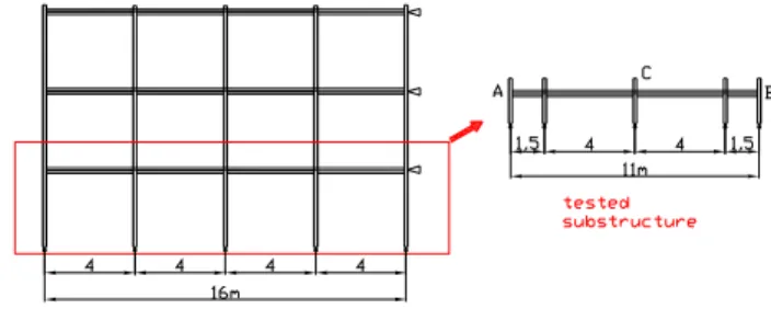
exhibit a similar behaviour than the one of the actual frame. To achieve this goal, the bottom storey has been isolated from the actual building and the width of the external spans has been then reduced (Figure 10).
The width of the concrete slab was chosen equal to 500mm, in order to ensure that, during the load-ing, the distribution of the stresses in the concrete was as uniform as possible; in fact, 500mm corre-sponds to the value of the effective width of the con-crete slab (under hogging moments) in the actual building, according to Eurocode 4 rules.
Figure 10. From the actual frame to the tested substructure
The 10 mm rebars used in the actual frame (see 2.2.2) have here been substituted by 8 mm ones, in order to increase the probability to develop a large number of small cracks in the slab, under hogging beam moments, instead of few big cracks and so to allow for more local ductility. Besides that the dis-tance between the first headed stud and the face of the column flange was larger than what is usually adopted and the amount of longitudinal re-inforcement within this area was kept constant (Fig-ure 11); as a consequence, the slab is subjected to constant tension forces in this zone, what results in an especially high ductile behaviour. This specific detailing has been investigated at Stuttgart Univer-sity (Kuhlmann et al, 2004) and its efficiency has been demonstrated.
Figure 11. Reinforcement and layout of shear studs
Column bases are assumed to be pinned. Teflon elements are used so as to limit the friction between the column steel supports and the pins during the loading. The composite joints in the substructure are the same as in the actual building (see 2.2.2). Only the external beams were simply connected to the ex-ternal columns so as to limit the number of pa-rameters which could influence the response of the internal beams during the test.
The response of the substructure should be as close as possible to the one of the reference frame. However by extracting the bottom storey of the ref-erence frame, reducing the length of the external beam spans and placing hinges at the external joints,
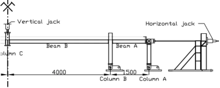
a key element has been modified: the frame restraint (K factor), which strongly influences the catenary action. That is why horizontal restraints were pro-vided at each side of the substructure (see point A and B in Figure 10) so as to simulate the actual frame restraints. Restraints were provided on both sides of the substructure in order to induce a sym-metrical response of the substructure during the test (see Figure 12); this should facilitate the application of the loads and the measurements during the test. In practice, the restraints were brought by two horizon-tal calibrated jacks (Figure 13); the restraint was as-sumed to be elastic until the end of the test and equal to the one exhibited by the actual structure.
K 2K 2K
Figure 12. From the unsymmetrical actual behaviour to the symmetrical test behaviour
Figure 13. Configuration of the substructure tested
The load path during the test was as follows:
− The substructure was first preloaded with an uni-formly distributed load on the internal beams to simulate the reaction of the concrete slab on the main frame in the actual building. During this loading phase, two locked jacks simulated the presence of the central column, as illustrated in Figure 14.
− In a second step, the support under the central column was progressively removed by unlocking the jacks; when the latter were removed, the free deflection of the system was observed. Finally, a vertical force was applied until collapse through a jack located above the structure on the column thus further deformations occurred (Figure 15). During the whole test the “K factor” simulating the frame restraint was kept constant.
Figure 14. Column at the middle simulated by two locked jacks
Figure 15. Application of a vertical load with vertical jacks un-til collapse
2.2.4 Substructure test results
The vertical reaction in the central column which is associated to the uniformly distributed load and to the self-weight of the substructure was equal to 33,5kN (value of the load at point “O” in Figure 16 presenting the evolution at point “C” of the vertical load versus the vertical displacement). After the ap-plication of the uniform load, the jacks were unlocked and progressively removed. The system was completely released when a deflection of 29mm was reached. At this stage, first cracks at the vicinity of the external joints were observed and first steel yielding zones were seen in the column web panel of the internal composite joint. This loading step corre-sponds to part “OA” of the curve in Figure 16; the structure was still in its elastic range of behaviour when “A” was reached.
Then, a vertical load was progressively applied until collapse. From point “A” to “B”, yielding pro-gressed until finally a beam plastic mechanism formed at point “B” (plastic hinges in the joints un-der sagging and hogging moments). During this stage, the cracks in the vicinity of the external com-posite joints were more pronounced and yielding of some steel joint components was observed (column web and beam flange in compression); also, for the internal composite joint, a separation of the end-plate and the column flange was seen under sagging moment.
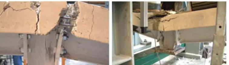
From point “B” to “C”, a yield plateau devel-oped; the concrete cracks in the vicinity of the ex-ternal composite joints continued to enlarge and yielding spreaded in the steel components. Another important phenomenon to be mentioned was the crushing of the concrete in the internal composite joints. At point “C”, significant membrane forces began to develop in the composite beams as con-firmed by the shape of the curve “CD” in Figure 16. When the point “D” was reached, the longitudinal rebars in the external composite joints failed in ten-sion and the concrete at the internal joint was fully crushed; at this moment, the joints worked as steel ones (Figure 17) and further plasticity developed in the different components of the internal and external composite joints. At point “D”, a loss of stiffness was observed which was linked to the loss of the longitudinal rebars in the vicinity of the external joints; indeed, when these rebars were lost, the ten-sile stiffness of the external joints decreased, phe-nomenon which affected the development of the membrane forces. At the end of the test (point “E”), a maximum vertical displacement of 775mm was reached for an applied vertical load of 114kN; the associated deformation of the specimen is shown in Figure 16. The maximum horizontal displacement at each side of the structure was equal to 45mm for a horizontal load of 147kN. The test was stopped when cracks occured in the welds connecting the
IPE140 profile to the end-plate in the internal com-posite joints, for a rotation of 190mRad.
-40 0 40 80 120 0 100 200 300 400 500 600 700 800 Deflection at the middle [mm]
Ja ck lo ad [k N ] O A B D C E
Figure 16. Vertical applied – “mid span” displacement curve
Figure 17. Internal and external composite joints at point “D” of Figure 16
2.3 First comparative experimental results Both composite joint tests as well as the substructure test showed the ability of the composite joints to un-dergo large rotations and to change the internal load combination from pure bending state to a combined bending and tension exposure. Failure was mainly induced by the concrete slab: for the hogging mo-ment joints by increased cracks and final rupture of the reinforcement, for the sagging moment joints by crushing of the concrete and decreasing of the con-crete compression zone. However also the steel joint components decisively contributed to the rotation capacity by bending of the endplate and column flange, tension of the column web or buckling of the column web under compression. In addition a re-markable resistance and ductility were left when the concrete slab had already failed. The tests even showed that the pure steel joints allowed a further increase of the joint rotation and resulting of this the membrane forces within the structure could be fur-ther increased. However to achieve this high ductil-ity all single relevant components had to be chosen such that a high local deformation could be fol-lowed. So the steel joint tests and the planned nu-merical investigations will have to give answers how to adapt strength and ductility of each of the single components to each other in order to achieve a duc-tile overall behaviour of the joint and a robust de-velopment of a biaxial loading resistance.
3 REFERENCES
ECCS Document No. 109. 1999. Design of Composite Joints for Buildings. ECCS Technical Committee 11-Composite
Structures, first edition 1999. Andersen, D.(ed.),Aribert, J.-M.; Bode, H.;Huber, G.; Jaspart, J.-P.; Kronenberger, H.-J.; Tschemmernegg, F
prEN 1994-1 Eurocode 4. 2004. Design of Composite Steel and Concrete Structures. Part 1: General rules for Build-ings, CEN, European Committee for Standardization EN 1993-1-8 Eurocode 3.2004. Design of Steel Structures –
Part 1-8: Design of Joints, European Committee for Stan-dardization
Kuhlmann U. & Schäfer M. 2004. “Innovative Verschiebliche Verbundrahmen mit Teiltragfähigen Verbundknoten”, Re-search Report, Insititut für Konstruktion und Entwurf, Uni-versität Stuttgart
EN 1991: Eurocode 1. 2002. Action on structures. part 1-1: General actions, Densities, self-weight, imposed loads for buildings. German version EN 1991-1-1
NBN EN 1994-1-1. 2005. Eurocode 4: Calcul des structures mixtes acier-béton – Partie 1-1: Règles générales et règles pour les bâtiments. February 2006.
4 CONCLUSION AND OUTLOOK
Progressive failure of the whole structure caused by local damage (e. g. failure of a column caused by a vehicle impact, explosion, fire, earthquake) can be prevented by robust design. Profiting from the in-herent ductile behaviour of steel, this project analyses the requirements for robustness and develops new ductile joint solutions to allow for force redistribution within the structure so that a global collapse of the building is prevented and structural safety is ensured. Criteria for robust structures, especially concerning steel and composite joints are elaborated and will be illustrated by drawings in a handbook for easy understanding and realization by the constructor.
The aim is to obtain robust structures by one small additional effort because mainly the inherent reserves of the structural system will be made avail-able for practical design no additional elements are needed to achieve redundancy.
To identify requirements for structures which originally have been designed for “normal” load combinations to behave robust under unexpected ex-ceptional loadings leads to a new view on structural safety which may be transferred to others than steel frame structures.
5 ACKNOWLEDGEMENT
The work presented here is carried out, as a joint research project by five different European partners here represented by the authors, with a financial grant from the Research Fund for Coal and Steel (RFCS) of the European Community. The authors gratefully acknowledge the financial support and es-timate the intensive cooperation among the col-leagues.