Open Archive TOULOUSE Archive Ouverte (OATAO)
OATAO is an open access repository that collects the work of Toulouse researchers and
makes it freely available over the web where possible.
This is an author-deposited version published in :
http://oatao.univ-toulouse.fr/
Eprints ID : 15961
To link to this article : DOI : 10.1016/j.surfcoat.2016.06.009
URL :
http://dx.doi.org/10.1016/j.surfcoat.2016.06.009
To cite this version : Caubert, Florent and Taberna, Pierre-Louis and
Arurault, Laurent Innovating pulsed electrophoretic deposition of
boehmite nanoparticles dispersed in an aqueous solution, into a
model porous anodic film, prepared on aluminium alloy 1050.
(2016) Surface and Coatings Technology, vol. 302. pp. 293-301.
ISSN 0257-8972
Any correspondence concerning this service should be sent to the repository
administrator:
[email protected]
Innovating pulsed electrophoretic deposition of boehmite nanoparticles
dispersed in an aqueous solution, into a model porous anodic film,
prepared on aluminium alloy 1050
Florent Caubert, Pierre-Louis Taberna
⁎
, Laurent Arurault
CIRIMAT, Université de Toulouse, CNRS, INPT, UPS, Université Toulouse 3 Paul Sabatier, Bât, CIRIMAT, 118 route de Narbonne, 31062 Toulouse cedex 9, France
a b s t r a c t
The present study investigates the pulsed electrophoretic deposition of boehmite particles, previously dispersed in an aqueous solution, into the pores of a model anodic film, prepared using phosphoric acid electrolyte, on an aluminium alloy 1050 (AA1050) substrate. Particles were successfully inserted into the pores, despite some lim-itations resulting both from the barrier layer, which transpired to be semi-conducting, and from water electrol-ysis. To address this issue, a pulsed electric field, set to above a threshold value, allowed a current to be sent through the cell, this being accompanied by a reduction of water electrolysis; insertion of particles thus became possible. Scanning Electron Microscope (FEG-SEM) observations, X-Ray Diffraction (XRD) spectroscopy and Elec-trochemical Impedance Spectroscopy (EIS) studies gave some clues as to the reality of particle impregnation into the pores. Furthermore, an improvement in the porous anodic film filling was achieved using hydrothermal post-treatment. Keywords: Anodic film Boehmite particles Electrophoretic deposition Hydrothermal post-treatment 1. Introduction
Porous anodic aluminium oxide films have been extensively used as a template for nanorod, nanotube and nanowire growth[1,2]. Overall, growth of these materials is achieved after having filled up the pores with a colloidal dispersion. Pore filling is usually achieved either by dip-coating[3]or electrophoretic deposition (EPD)[1,2,4]. However, as anodic films exhibit a more complicated geometry, the insertion of particles from colloid dispersion without an electric field[5]is more problematic. In such cases, electrophoretic deposition has been reported to be successful for nanoparticle deposition onto non-planar surfaces
[6–8].
Usually organic media are used as they provide high ranges of elec-trode potential[9]. To respond to environmental concerns, an aqueous medium remains a good option. Nevertheless, due to water electrolysis, the cell potential is limited, with the release of hydrogen and oxygen oc-curring on the electrodes and affecting the quality of the formed deposit
[10,11].
To counter this phenomenon, a number of techniques have been studied in the literature. For example, deposition on a palladium sub-strate is possible in an aqueous medium thanks to the absorption by the palladium of the hydrogen released by electrolysis[12]. Also, Sakurada et al.[13]report that adding hydroquinone into the solution
increases the deposition weight thanks to its reaction with the O2
gases released. Besra et al.[14,15]can also be cited as having succeeded in reducing bubble formation using a pulsed electric field. So the sol destabilisation due to higher pH is countered[16].
One key advantage of electrophoretic deposition over other process-es such as dip-coating liprocess-es in the ability to achieve deposits onto or into substrates characterised by tortuous or complex surfaces. For example, Limmer et al.[1]used an anodic aluminium oxide membrane as a tem-plate to ensure nanorod and nanotube growth. Meanwhile, Seo et al.
[17]showed how pores could potentially be filled using a dip-coating process, but only a reduced quantity at the bottom of the pores was ob-served using this method. Kamada et al.[5]studied the insertion of SiO2
particles into anodic films stimulated by an electric field. However, they used an aqueous medium, so due to water splitting, only incomplete fill-ing of the pores was obtained. Fori et al.[18,19]responded to this issue by using an organic based dispersion of SiO2particles, leading to
com-plete filling of the pores, thus successfully avoiding side reactions such as solvent electrolysis. Despite the difficulties encountered in using an aqueous medium for EDP, Kusdianto et al.[20]reported the potential to fill pores of less than 1 μm in length using a pulsed electric field to limit water splitting, while Escobar and al.[21,22]managed to incorpo-rate PTFE particles in 10 μm thick anodic film.
It is usually considered that:
- anodic films are made of hydrated alumina (Al2O3,xH2O)[23–26]
- the usual hydrothermal sealing (performed just after anodisation in ⁎ Corresponding author.
E-mail address:[email protected](P.-L. Taberna).
hot water at about 98 °C) occurs only at the top (i.e. the first 1 or 2 μm) of the porous anodic films.[27–30]
- the usual hydrothermal sealing of porous anodic films prepared in phosphoric acid based electrolyte is extremely difficult[31], as com-pared with other types of anodic films.
So there are now two main challenges:
- the first is to insert boehmite (AlOOH) particles all along the pores of the anodic films, in order to promote on the one hand chemical in-teractions of these particles with the pore walls, and on the other hand complete sealing during final hydrothermal post-treatment. - the second challenge is to successfully conduct efficient sealing all
along the pores of such phosphoric anodic films.
The present work aimed at achieving pulsed electrophoretic deposi-tion of boehmite nanoplatelets dispersed in an aqueous soludeposi-tion into a model porous anodic film prepared by anodisation in a phosphoric acid electrolyte. EPD of the boehmite particles into the anodic film was studied and improved, especially through the investigation of vari-ous operational parameters, such as colloidal dispersion conductivity and the type of electric field for electrophoretic deposition. Then, filling of the boehmite particles and sealing of the anodic film were respective-ly characterised by FEG-SEM observations and XRD anarespective-lysis, and evalu-ated by EIS, in relation to its global electrical behaviour.
2. Experimental methods
2.1. Preparation of a model porous anodic film on an AA 1050 substrate
Aluminium alloy 1050 substrates (99.5% Al, b0.40% Fe, b0.25% Si and b 0.05% Cu) were treated following a three step procedure (degreasing, etching and acid neutralisation). Firstly, aluminium sheets (20 mm × 20 mm × 1 mm) were degreased with ethanol. They were then etched by immersion in an NaOH solution (25 g·L− 1) at 40 °C for
5 min. and neutralised in an HNO3solution ( 25vol%) at room
tempera-ture for 2 min. After rinsing in deionised water (106
Ω·cm), the alumin-ium sheets were used as an anode while a lead plate (50 mm × 40 mm × 2 mm) provided a cathode. The specimens were galvanostatically anodised in a phosphoric bath (0.4 mol·L− 1) at 25 °C
and at a current density of 1.5 A·dm− 2for 29 min. Finally, the anodic
film obtained was thoroughly rinsed in deionised water. This model po-rous anodic film, presented inFig. 1, had a thickness of 9.5 ± 0.3 μm with two layers. The first was made up of linear (and orthogonal to the AA substrate) pores, showing a diameter of 129 ± 3 nm, while the second was a barrier layer with a thickness of 130 ± 6 nm.
2.2. Electrophoretic deposition of boehmite nanoparticles
A synthesised colloid suspension of boehmite nanoparticles in aque-ous media was used. This suspension was prepared by hydrolysis of an aluminium alkoxide, according to the Yoldas process[32]. A supplement of deionised water (H2O/Al = 100) at 85 °C was quickly added to 25.3 g
of aluminium tri-sec-butoxide (Al(OC4H9)3) and stirred for 15 min. The
white sol obtained was peptised by adding 0.2 mol of nitric acid (HNO3)
per mole of alkoxide in order to control the surface potential on the par-ticles and avoid agglomeration. The mixture was then continuously stirred at 85 °C for 24 h using a thermostat system and finally showed a concentration of around 0.5 mol·L− 1. Electrophoretic impregnations
of particles into the model anodic film were performed with anodised aluminium as the cathode, while lead foil as the anode was located at about 2.5 cm.
2.3. Characterisations
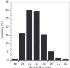
A Transmission Electric Microscope (TEM) was used to measure the particle size and characterise the morphology. The size population was defined by picture analysis using ImageJ software.
Surface and cross-sectional views of the coatings were performed by Field Emission Gun Scanning Electron Microscope (FEG-SEM) in order to prove the possible insertion of particles into the model porous anodic film.
To determine the particle microstructure, the suspension was previ-ously dried in the open air. The xerogel thus obtained was then ground to obtain a powder, which was finally analysed by X-ray diffraction (XRD). XRD analysis was performed with a Brucker AXS D4 ENDEAVOR device using Bragg-Brentano θ-2θ geometry with a copper anticathode (CuKα, λ = 1.541Å). XRD diagrams were obtained in the 20–100° (2θ) range. Peak determination was finally made using the JCPDS card 21-1307, corresponding to an orthorhombic structure boehmite.
The anodic films were characterised by X-ray diffraction at grazing incidence (1°). The measurements were performed in the 20–80° range using a SIEMENS D5000 device with a copper anticathode (CuKα, λ = 1.541Å).
The electric behaviour of the samples was monitored using Electro-chemical Impedance Spectroscopy (EIS) during immersion in a neutral solution of Na2SO4(0.5 mol·L− 1) at room temperature. A three
elec-trode electrochemical cell was used, with a platinum foil as counter-electrode and a mercury sulphate saturated (saturated calomel) elec-trode as the reference elecelec-trode. The EIS measurements ranged from 105to 5.10− 2Hz and were performed using an SP-150 BioLogic Science
Instrument.
Stokes diameters of the nanoparticles were measured by Dynamic Light Scattering using a ZS90 Malvern nanosizer with Zetasizer software.
3. Results and discussions
3.1. Characterisation of boehmite nanoparticles
Boehmite particles in an aqueous medium were chosen for two rea-sons. Firstly, as an aqueous based solution it responds to environmental concerns. Secondly, particle chemical composition is very close to the chemical content of the anodic porous film, which may improve chem-ical affinity. The boehmite particles were synthesised using the Yoldas process and exhibited a needle-like morphology, as previously characterised by Alphonse et al.[33]. An average Stokes diameter for the boehmite particles was about 40 nm (Fig. 2), which is below the mean pore diameter (129 nm).
Moreover, as observed inFig. 3, showing the particles' electropho-retic mobility, a positive value was noted (2.7 μm cm·V− 1·s−1). The
lat-ter enables the particles to deposit on the negative electrode (cathode) avoiding any further oxidation of the substrate (i.e. over-oxidation of the anodised aluminium in this case).
Moreover, the XRD pattern (Fig. 4) shows on the one hand that the particles are crystallised, at least partially. On the other hand, Bragg peak indexation is consistent[33]with orthorhombic structure boehm-ite. In this case, peak (020) is higher than peaks (200) and (002), which difference could be explained by the fact that the distances along the a and c axes are greater than those along b, with boehmite having a plate-let shape. The crystal structure of boehmite particles could allow their potential identification after impregnation in the anodic film, which is itself amorphous.
3.2. Particle impregnation into the porous anodic film 3.2.1. Impregnation without polarisation
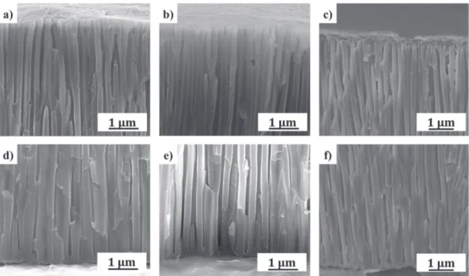
Impregnation without polarisation is equivalent to dip-coating. The aim is to determine whether the insertion of particles by capillarity into the model porous anodic film is possible spontaneously. To this purpose, dip-coating was performed with a withdrawal rate of 25 mm.min-1. The FEG-SEM cross-sectional view (Fig. 5a and d) only
shows a few particles at the bottom of the pores with none at the top. Additionally, the XRD diffraction patterns obtained, using grazing inci-dence, respectively for the bare anodic film (Fig 6a) and the impregnat-ed film (Fig. 6b), have very similar shapes. In both cases, there is only one peak (located at about 64°), attributed to the underlying aluminium substrate. By contrast, the possible presence of particles within the model anodic film was not demonstrated after dip-coating, despite the crystallised character of the particles in comparison to the amorphous anodic film. In the most optimistic case, the filling rate was so slow
that the particles could not be characterised. Particle impregnation by capillarity does not therefore allow anodic film filling to be obtained.
As shown inFig. 3and demonstrated by Diggle et al.[34], as both particles and pore walls are positively charged, particle insertion will be hindered considerably and the pores will therefore only be filled by particle-free solvent. The presence of some particles inside the pores would appear to result from the solvent drying, as already observed by some authors[35,36]. This result is consistent with what was report-ed by Fori et al.[18]and argues in favour of using an electric field to im-prove the insertion of boehmite nanoparticles into the pores.
3.2.2. Impregnation by constant and pulsed electric field
3.2.2.1. Influence of the barrier layer. The challenge here was to determine
the appropriate potential range to be applied. On the one hand, too high a potential will lead to gas being released from water electrolysis; on the other hand, anodic films are known to exhibit rather high impedance. As observed inFig. 7, the current density measured is very low at cell po-tential lower than 3 V. During the first few seconds of deposition, an ex-ponential decay is observed; this is typically observed behaviour for a capacitive electrochemical interface.
This observation is readily explained by the presence of the barrier layer at the aluminium interface, known to be a dielectric material. In addition, as reported elsewhere[37–39], this layer behaves like an
n-Fig. 2. Particle size distribution.
Fig. 3. Electrophoretic mobility of boehmite nanoparticle suspension.
type semi-conductor with a specific threshold potential depending on the electrolytic medium used during barrier layer formation. Indeed, during the formation of anodic films, anions from the electrolyte (phos-phate) and water are incorporated into the barrier layer[23,34]and act as electronic trappers.
To define the threshold potential of the anodic film, an electrochem-ical impedance spectroscopy study was performed at different poten-tials in a boehmite dispersion. Firstly,Fig. 8shows the EIS curves for different applied potentials. As can be seen in the figure, at f = 105Hz and whatever the applied potentials, the value is identical and is known to be the resistance of the electrolyte[40–42]. A dispersion con-ductivity of 5.35 mS·cm− 1was calculated, while the value measured
using a regular conductimeter was 5.11 mS·cm− 1.
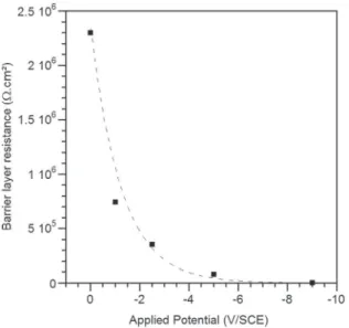
As reported elsewhere[40–42], the low frequency impedance is driven by the electric behaviour of the barrier layer. This aspect is
stressed inFig. 9where the variation of the low frequency resistance, extracted from the real part of the impedance, is plotted as a function of the applied potential. As expected, the general trend is well described by an exponential decay law (y = 2.106e0.8x, R2= 0.982), typical for a
diode-like behaviour as depicted by other authors[37,38]. These results show that a minimum potential of −3 V/SCE (defined here as the threshold potential) is needed to cause the current to pass through the cell, with the barrier layer becoming conductive. Overall, this kind of behaviour should enable the migration of particles inside the pores.
3.2.2.2. Influence of dispersion conductivity on the threshold potential. Fori
et al.[19]have already shown (although in organic media), that to ob-tain the migration of particles into the pores it was necessary to increase the conductivity of the solution: the interaction between particles and Fig. 5. FEG-SEM cross-sectional views of the model porous anodic film after dip-coating (a) top and d) bottom of the pores), after constant EPD (b) top and e) bottom of the pores) and after pulsed EPD (c) top and f) bottom of the pores).
Fig. 6. XRD spectra of a) the bare anodic film, b) after dip-coating, c) after direct EPD, d) after pulsed EDP, e) after pulsed EPD followed by hydrothermal post-treatment.
Fig. 7. Current density changes during a constant electrophoretic deposition (3 V, 5 min) of boehmite particles on/in the model anodic porous film.
pore walls is reduced thanks to the electric double-layer compression of both the pore/electrolyte and the particle/electrolyte interfaces. They also demonstrated that increasing conductivity of the dispersion led to focusing the electric field on the anodic film region, improving particle impregnation throughout the anodic film.
Surprisingly, in the case of water-based dispersion, things are rather more complex since the threshold potential appears (Fig. 10) to be re-lated to dispersion conductivity. Somehow, the physico-chemical char-acteristics of the barrier layer seem to evolve with the dispersion composition.Fig. 10is obtained by measuring the impedance of an an-odic film soaked in dispersions exhibiting different conductivities, achieved by the dilution of a boehmite stock solution with a certain vol-ume of deionised water (106
Ω·cm). As can be seen inFig. 10, a signifi-cant threshold potential variation was observed (ranging from −2 to − 5 V vs SCE). This is of importance since, when the applied electric field is lower than the threshold potential, deposition into the pores is hindered. Conversely, deposition is possible at lower potential but is ac-companied by the reduction of water involving H2gas release.
On the cathode, a pH increase occurs (the isoelectric point is approx-imately at pH 8[43,44]) leading to dispersion destabilisation and thus
aggregation of the particles. Thus, the challenge lies in obtaining suffi-cient potential to promote particle migration while also hindering bub-ble formation detrimental to achieving an even deposit, especially with the impregnation of particles into the pores. When conductivity is low, electrolysis is high (σ b 1.5 mS·cm− 1) and most of the deposit is
obtain-ed at the surface of the anodic film with this deposit exhibiting poor me-chanical stability, whereas dispersion destabilisation is reduced at the interface for high conductivity (lower current). This result suggests that an increase in conductivity limits the influence of water electrolysis on the quality of deposition.
Fig. 11. FEG-SEM cross-sectional (a) global view and (b) bottom view (with the contour of the deposit highlighted in yellow) of the model porous anodic film after pulsed EPD. (For interpretation of the references to colour in this figure legend, the reader is referred to the web version of this article.)
Fig. 10. Threshold potential of barrier layer according to the boehmite suspension conductivity.
Fig. 9. Barrier layer resistance according to the potential applied during the EIS measurements.
Fig. 8. Variations of impedance modulus (Bode plot) with applied potential, for the bare model porous anodic film immersed in boehmite dispersion.
When a constant potential close to the threshold potential is applied, hardly any particle insertion is obtained (Fig. 5b and e). As observed previously, the presence of particles is difficult to highlight clearly using FEG-SEM observations, and therefore additional XRD analysis was performed (Fig. 6c). The resulting spectrum was compared with that of the bare anodic film and a small peak was observed at an angle of 38°, corresponding to the plane (130) boehmite and suggesting pos-sible insertion of particles within the pores (to be confirmed).
To increase yield, a higher current is required, also meaning a higher potential. However, greater gas release will result, this being detrimen-tal to particle insertion into the pores.
3.2.2.3. Pulsed electrophoresis. To address this issue, Besra et al.[14,15]
showed that a pulsed potential leads to a slowdown in gas release while the increase in pH remained low. They found that a low duty cycle (DC = Ton/(Ton+ Toff)) was preferable to obtain an even deposit.
Based on these results, EPD was performed using a DC of 10%, and com-pared to EPD under constant potential.
InFigs. 5c and f and11, FEG-SEM cross-sectional views of anodic po-rous film (obtained after a pulsed electrophoretic deposition) show the presence of particles at the bottom of the pores, on the pore walls, along the anodic film and at the top of pores.
The coating was also analysed by X-ray diffraction under grazing in-cidence (Fig. 6d). The resulting XRD spectrum shows a peak at an angle of 38°, corresponding to the plane (130) boehmite. This result would appear to attest to the possible insertion of particles within the pores of the model anodic film. This peak is also identical (in location and in-tensity) to that obtained during an electrophoretic impregnation with DC voltage, which raises the question as to the real contribution of a pulsed voltage on the quantity of inserted particles, compared with a DC voltage. However, these characterisations do not allow for a rigorous quantitative analysis of the particles within the pores. Nevertheless, FEG-SEM images (Fig. 11) show that particles are present, and more conclusively so after impregnation under pulsed polarisation.
A mechanism for deposition into pores was proposed by Fukunaka et al.[45]as also by Ponrouch et al.[46]. As application time Tonwas
lim-ited, only a small amount of hydrogen was produced, preventing any bubbles from coalescing and keeping them small enough to ensure their evacuation during time Toff. This phenomenon was well described
by Ponrouch et al.[46]for cathodic deposition of Ru in anodised alumin-ium oxide membranes.
The outcome is that using pulsed deposition appears to improve par-ticle incorporation inside the porous anodic film. To take matters fur-ther, hydrothermal post-treatment was applied to increase hydration (and so the molar volume) of both the anodic film and the particles and ideally improve pore filling[29,47].
3.3. Influence of hydrothermal post-treatment
Chang et al.[48]used hydrothermal synthesis in an autoclave to cre-ate aluminium oxy-hydroxide (AlOOH) nanorods and nanotubes in the pores of an anodic film using a phosphoric bath that included alumini-um oxalate. The idea was to induce the particles to grow within the pores using hydrothermal post-treatment. The present study pursued this idea by studying the influence of hydrothermal post-treatment (water at 98 °C for 2 h) of the previously prepared samples (i.e. bare an-odic film) before and after dip-coating or EPD.
Fig. 12shows the model anodic film after post-treatment in hot water (i.e. without previous EPD of boehmite particles). No change
Fig. 13. FEG-SEM cross-sectional views of the model porous anodic film after dip-coating (a) top and d) bottom of the pores), after constant EPD (b) top and e) bottom of the pores) and after pulsed EPD (c) top and f) bottom f of the pores) and each time with hydrothermal post-treatment (deionised water at 98 °C, 2 h).
Fig. 12. FEG-SEM cross-sectional view of the model porous anodic film after a hydrothermal post-treatment (deionised water at 98 °C, 2 h).
was observed, showing that the usual hot water sealing is ineffective for this type of anodic film prepared in phosphoric acid electrolyte, as pre-viously claimed[31].
By contrast, for a hydrothermal post-treatment after dip-coating, or continuous or pulsed electrophoretic deposition, filling all along the pores was achieved (Figs. 13 and 14). XRD analysis was also performed to detect the presence of boehmite particles after these various treat-ments. The XRD spectrum corresponding to the pulsed EPD followed by hydrothermal post-treatment (Fig. 6e) showed several peaks, attrib-uted to those of boehmite. This result suggests that the particles detect-ed after EPD crystallisdetect-ed during hydrothermal post-treatment.
These results seem to confirm either the presence of particles before post-treatment was applied or a deep modification of the anodic film, since it has so far proven practically impossible to clearly observe parti-cles in FEG-SEM observations, whatever the chosen path for insertion, i.e. dip-coating or constant electrophoretic deposition. Possibly, hydro-thermal post-treatment acted here as a developer. In all events, it would appear that filling after constant EPD followed by post-treatment was less effective than dip-coating or pulsed EPD. It can be assumed that the larger bubbles formed during the constant potential process may limit particle impregnation. Nevertheless, no clear evidence was obtain-ed regarding the efficiency of pore filling depending on the process. An EIS study was then performed to provide greater insight, since some variations in the impedance are expected with the filling ratio of the pores. Fig. 15 shows the Bode diagrams obtained in Na2SO4
(0.5 mol·L− 1) for three different modified anodic films: the first by
dip-coating and the others by constant or pulsed EPD, all of them being hydrothermally treated in the same conditions.
InFig. 15, at low frequency (f b 10− 1Hz), a decrease in impedance
modulus is observed for each process in comparison with the bare an-odic film. This value shows a reduction in the barrier layer homogeneity. Electrophoretic and hydrothermal treatments may modify the structure of the barrier layer and, as a result, its electric behaviour[49,50]. More-over, for non-modified anodic film, as well as modified anodic film by
dip-coating and constant EPD, the presence of one time constant only is observed. Mansfeld et al.[51]claimed that when only one time con-stant is observed, the pores are not completely closed, this being the case for the non-modified porous anodic film. In the case of pulsed EPD, a second time constant is visible in the Bode diagram phase; in the latter case a new time constant clearly emerges for a frequency value close to 5.102
Hz and gives some clues as to the filling of pores by the growth of particles under hydrothermal treatment.
In previous studies[40–42], the electric behaviour of the anodic film was modelled by an equivalent electric circuit including resistances and capacitances. A classic model is presented inFig. 16a, where the resis-tance Relecdenotes the resistance of the electrolyte (bulk and electrolyte
entering the pores), Rpand Cprepresent the resistance and capacitance
of the porous layer, and Rband Cbthe resistance and capacitance of the
barrier layer. Capacitive behaviour is best simulated by constant phase elements (CPE with a non-perfect capacitance Q and a coefficient α), while Q is defined by C = (R.Q)1/α/R where α is the frequency
disper-sion factor (0 b α b 1) related to the heterogeneity of layers thanks to the incorporation of alloying elements and penetration of electrolyte during anodisation. When α = 1, Q is a perfect capacitance. In the case of a non-filled porous layer, the equivalent circuit can be simplified as shown inFig. 16b by the newly introduced resistance Rtot, including
Relec, Rpand Qpand, as the pores are only filled by electrolyte, Rpand
Cpcan be neglected.
Fig. 16. Equivalent circuits used for modelling the anodic film electric behaviour: a) classic model and b) simplified model (for α = 1).
Fig. 15. Variations of impedance modulus (Bode plot) in Na2SO4(0.5 mol·L− 1) for the
model porous anodic film before and after dip-coating, or constant EPD or pulsed EPD followed each time by a hydrothermal post-treatment (deionised water at 98 °C, 2 h).
Fig. 14. FEG-SEM cross-sectional view at the bottom of the model porous anodic film after pulsed EPD and hydrothermal post-treatment (deionised water at 98 °C, 2 h).
As explained previously, low frequencies are associated with the barrier layer electric characteristics, whereas the high frequency region concerns the porous layer and electrolyte. To determine the electric be-haviour of the porous layer after treatment, impedance curves are fitted into the high frequency field (f N 103Hz).Table 1summarises the
elec-tric element values obtained by fitting using the equivalent elecelec-tric cir-cuit previously described and observation of the new slope at high frequency (f = 105Hz) in the case of pulsed EPD.Table 1highlights a
new capacitance Cpwith a coefficient αp. In fact, the value of resistance
Rpis too high and corroborates the fact that the electric behaviour is
al-ways driven by the barrier layer. Sealing, in the case of dip-coating and constant EPD, is not efficient enough (Fig. 15) but the pores are at least partially filled.
EPD allows the resistance of the porous layer to be increased thanks to the growth of particles during post-treatment but proves more effi-cient when pulsed. These results suggest that there is significant filling of the pores with particles effectively penetrating thanks to pulsed EPD. 4. Conclusion
The insertion of boehmite nanoparticles from an aqueous medium into a porous anodic film proved impossible using dip-coating due to electrostatic repulsion between the pore walls and the particles. How-ever, using a combination of electrophoretic deposition and hydrother-mal post-treatment, impregnation became possible. This was achieved after assessing the threshold potential of the barrier layer, known to be-have like a semi-conductor. This aforementioned threshold potential was found to depend on the conductivity of boehmite dispersion. In an aqueous medium, water electrolysis was seen to be hindered when using pulsed EPD with optimised boehmite dispersion (σ = 3 mS·cm− 1). Hydrothermal post-treatment resulted in complete pore
filling, whether dip-coating or electrophoretic deposition was per-formed, thus revealing the presence of particles within the pores. An ad-ditional EIS study confirmed the presence of particles, since a high frequency time constant emerged; the related resistance Rpand
capac-itance Cpwere linked to porous anodic film filling. This was only
ob-served when a constant or pulsed electrophoretic deposition was applied, proving the need to apply an electric field to assist particle in-corporation. In addition, since a higher resistance was measured during the pulsed EPD process, more efficient filling was assumed to be achieved in that case.
Acknowledgements
The present work was conducted as a part of the ECOREV project. The Regional Councils of Midi-Pyrénées and Mecaprotec Industries are gratefully acknowledged for the financial support (n°11052675) they provided for this project.
References
[1]S.J. Limmer, S. Seraji, Y. Wu, T.P. Chou, C. Nguyen, G.Z. Cao, Template-based growth of various oxide nanorods by sol-gel electrophoresis, Adv. Funct. Mater. 12 (2002) 59–64.
[2] G. Cao, Growth of oxide nanorod arrays through sol electrophoretic deposition, J. Phys. Chem. B 108 (2004) 19921–19931.
[3]S. Hirai, K. Shimakage, M. Sekiguchi, K. Wada, A. Nukui, Zirconium oxide coating on anodized aluminum by the sol-gel process combined with ultraviolet irradiation at ambient temperature, J. Am. Ceram. Soc. 82 (1999) 2011–2015.
[4] B.B. Lakshmi, C.J. Patrissi, C.R. Martin, Sol-gel template synthesis of semiconductor oxide micro-and nanostructures, Chem. Mater. 9 (1997) 2544–2550.
[5]K. Kamada, H. Fukuda, K. Maehara, Y. Yoshida, M. Nakai, S. Hasuo, et al., Insertion of SiO2nanoparticles into pores of anodized aluminum by electrophoretic deposition
in aqueous system, Electrochem. Solid-State Lett. 7 (2004) B25–B28.
[6] O.O. Van der Biest, L.J. Vandeperre, Electrophoretic deposition of materials, Annu. Rev. Mater. Sci. 29 (1999) 327–352.
[7]A.R. Boccaccini, O. van der Biest, J.B. Talbot, "Electrophoretic Deposition, Fundamen-tals and Applications", The Electrochemical Society, Pennington, US, 2002.
[8]L. Besra, M. Liu, A review on fundamentals and applications of electrophoretic depo-sition (EPD), Prog. Mater. Sci. 52 (2007) 1–61.
[9]L. Stappers, L. Zhang, O. Van der Biest, J. Fransaer, The effect of electrolyte conductiv-ity on electrophoretic deposition, J. Colloid Interface Sci. 328 (2008) 436–446.
[10] M.S. Djošić, V.B. Mišković-Stanković, D.T. Janaćković, Z.M. Kačarević-Popović, R.D. Petrović, Electrophoretic deposition and characterization of boehmite coatings on ti-tanium substrate, Colloids Surf. Physicochem. Eng. Asp. 274 (2006) 185–191.
[11] B. Neirinck, J. Fransaer, O.V. der Biest, J. Vleugels, Aqueous electrophoretic deposition in asymmetric AC electric fields (AC–EPD), Electrochem. Commun. 11 (2009) 57–60.
[12] F. Tang, T. Uchikoshi, K. Ozawa, Y. Sakka, Electrophoretic deposition of aqueous nano-γ-Al2O3suspensions, Mater. Res. Bull. 37 (2002) 653–660.
[13] O. Sakurada, K. Suzuki, T. Miura, M. Hashiba, Bubble-free electrophoretic deposition of aqueous zirconia suspensions with hydroquinone, J. Mater. Sci. 39 (2004) 1845–1847.
[14] L. Besra, T. Uchikoshi, T.S. Suzuki, Y. Sakka, Bubble-free aqueous electrophoretic depo-sition (EPD) by pulse-potential application, J. Am. Ceram. Soc. 91 (2008) 3154–3159.
[15] L. Besra, T. Uchikoshi, T.S. Suzuki, Y. Sakka, Pulsed-DC electrophoretic deposition (EPD) of aqueous alumina suspension for controlling bubble incorporation and de-posit microstructure, Key Eng. Mater. 412 (2009) 39–44.
[16] L. Besra, T. Uchikoshi, T.S. Suzuki, Y. Sakka, Experimental verification of pH localiza-tion mechanism of particle consolidalocaliza-tion at the electrode/solulocaliza-tion interface and its application to pulsed DC electrophoretic deposition (EPD), J. Eur. Ceram. Soc. 30 (2010) 1187–1193.
[17] I. Seo, C.-W. Kwon, H.H. Lee, Y.-S. Kim, K.-B. Kim, T.-S. Yoon, Completely filling anod-ic aluminum oxide with maghemite nanopartanod-icles by dip coating and their magnetanod-ic properties, Electrochem. Solid-State Lett. 12 (2009) K59–K62.
[18] B. Fori, P.-L. Taberna, L. Arurault, J.-P. Bonino, C. Gazeau, P. Bares, Electrophoretic im-pregnation of porous anodic aluminum oxide film by silica nanoparticles, Colloids Surf. Physicochem. Eng. Asp. 415 (2012) 187–194.
[19] B. Fori, P.L. Taberna, L. Arurault, J.P. Bonino, Decisive influence of colloidal suspen-sion conductivity during electrophoretic impregnation of porous anodic film sup-ported on 1050 aluminium substrate, J. Colloid Interface Sci. 413 (2014) 31–36.
[20] K. Kusdianto, M.N. Naim, K. Sasaki, I.W. Lenggoro, Immobilization of colloidal parti-cles into sub-100 nm porous structures by electrophoretic methods in aqueous media, Colloids Surf. Physicochem. Eng. Asp. 459 (2014) 142–150.
[21] J. Escobar, L. Arurault, V. Turq, Improvement of the tribological behavior of PTFE-an-odic film composites prepared on 1050 aluminum substrate, Appl. Surf. Sci. 258 (2012) 8199–8208.
[22] J. Escobar, Elaboration et caractéristisations de films anodiques composites lubrifiants à base de PTFE sur substrat d'aluminium, Université Toulouse III - Paul Sabatier, 2013.
[23] G.E. Thompson, Porous anodic alumina: fabrication, characterization and applica-tions, Thin Solid Films 297 (1997) 192–201.
[24] C.A. Melendres, S. Van Gils, H. Terryn, Toward a quantitative description of the anodic oxide films on aluminum, Electrochem. Commun. 3 (2001) 737–741.
[25] F. Le Coz, L. Arurault, S. Fontorbes, V. Vilar, L. Datas, P. Winterton, Chemical compo-sition and structural changes of porous templates obtained by anodizing aluminium in phosphoric acid electrolyte, Surf. Interface Anal. 42 (2010) 227–233.
[26] F. Le Coz, L. Arurault, L. Datas, Chemical analysis of a single basic cell of porous an-odic aluminium oxide templates, Mater. Charact. 61 (2010) 283–288.
[27] K. Wefers, The mechanism of sealing of anodic oxide coatings on aluminium Part 1, Aluminium 49 (1973) 553–561.
[28] K. Wefers, The mechanism of sealing of anodic oxide coatings on aluminium Part 2, Aluminium 49 (1973) 622–624.
[29] G. Patermarakis, N. Papandreadis, Effect of the structure of porous anodic Al2O3films
on the mechanism of their hydration and pore closure during hydrothermal treat-ment, Electrochim. Acta 38 (1993) 1413–1420.
[30] L. Domingues, J.C.S. Fernandes, M. Da Cunha Belo, M.G.S. Ferreira, L. Guerra-Rosa, Anodising of Al 2024-T3 in a modified sulphuric acid/boric acid bath for aeronauti-cal applications, Corros. Sci. 45 (2003) 149–160.
[31] G.D. Davis, T.S. Sun, J.S. Ahearn, J.D. Venables, Application of surface behaviour dia-grams to the study of hydration of phosphoric acid-anodized aluminium, J. Mater. Sci. 17 (1982) 1807–1818.
[32] B.E. Yoldas, Alumina gels that form porous transparent Al2O3, J. Mater. Sci. 10 (1975)
1856–1860.
[33] P. Alphonse, M. Courty, Structure and thermal behavior of nanocrystalline boehmite, Thermochim. Acta 425 (2005) 75–89.
[34] J.W. Diggle, T.C. Downie, C.W. Goulding, Anodic oxide films on aluminum, Chem. Rev. 69 (1969) 365–405.
[35] K. Nagayama, Two-dimensional self-assembly of colloids in thin liquid films, Col-loids Surf. Physicochem. Eng. Asp. 109 (1996) 363–374.
[36] P.A. Kralchevsky, K. Nagayama, Capillary interactions between particles bound to in-terfaces, liquid films and biomembranes, Adv. Colloid Interf. Sci. 85 (2000) 145–192.
Table 1
Experimental values of different electric elements of the equivalent electric circuit obtain-ed by fitting of the EIS experimental curves.
Rtot(Ω·cm2) Rp(Ω·cm2) αp Cp(F·cm− 2)
Anodic film 1.77 2.98·107 0.96 0.92·10− 7
Dip-coating + Post-treatment 14.15 1.10·1017 0.91 1.78·10− 6
Constant EPD + Post-treatment 12.4 3.60·1017 0.80 0.17·10− 3
[37]I. Vrublevsky, A. Jagminas, J. Schreckenbach, W.A. Goedel, Electronic properties of electrolyte/anodic alumina junction during porous anodizing, Appl. Surf. Sci. 253 (2007) 4680–4687.
[38] L. Arurault, G. Zamora, V. Vilar, P. Winterton, R. Bes, Electrical behaviour, character-istics and properties of anodic aluminium oxide films coloured by nickel electrode-position, J. Mater. Sci. 45 (2010) 2611–2618.
[39] G. Zamora, L. Arurault, P. Winterton, R. Bes, Impact of the type of anodic film formed and deposition time on the characteristics of porous anodic aluminium oxide films containing Ni metal, Chem. Pap. 65 (2011) 460–468.
[40] T.P. Hoar, G.C. Wood, The sealing of porous anodic oxide films on aluminium, Electrochim. Acta 7 (1962) 333–353.
[41] J. Hitzig, K. Jüttner, W.J. Lorenz, W. Paatsch, AC-impedance measurements on porous aluminium oxide films, Corros. Sci. 24 (1984) 945–952.
[42] J.A. González, V. López, A. Bautista, E. Otero, X.R. Nóvoa, Characterization of porous aluminium oxide films from a.c. impedance measurements, J. Appl. Electrochem. 29 (1999) 229–238.
[43] R. Sprycha, Electrical double layer at alumina/electrolyte interface: I. Surface charge and zeta potential, J. Colloid Interface Sci. 127 (1989) 1–11.
[44] S. Novak, K. König, Fabrication of alumina parts by electrophoretic deposition from ethanol and aqueous suspensions, Ceram. Int. 35 (2009) 2823–2829.
[45]Y. Fukunaka, M. Motoyama, Y. Konishi, R. Ishii, Producing shape-controlled metal nanowires and nanotubes by an electrochemical method, Electrochem. Solid-State Lett. 9 (2006) C62–C64.
[46] A. Ponrouch, M.P. Bichat, S. Garbarino, C. Maunders, G. Botton, P.-L. Taberna, et al., Synthesis and characterization of well aligned Ru nanowires and nanotubes, ECS Trans. 25 (2010) 3–11.
[47]G. Patermarakis, P. Kerassovitou, Study on the mechanism of oxide hydration and oxide pore closure during hydrothermal treatment of porous anodic Al2O3films,
Electrochim. Acta 37 (1992) 125–131.
[48] Y. Chang, Z. Ling, Y. Li, X. Hu, Hydrothermal synthesis of aluminum oxy-hydroxide nanorod and nanotube arrays, Electrochim. Acta 93 (2013) 241–247.
[49] X. Zhao, Y. Zuo, J. Zhao, J. Xiong, Y. Tang, A study on the self-sealing process of anodic films on aluminum by EIS, Surf. Coat. Technol. 200 (2006) 6846–6853.
[50] H.-J. Oh, K.-W. Jang, C.-S. Chi, Impedance characteristics of oxide layers on alumini-um, Bull. Kor. Chem. Soc. 20 (1999) 1340–1344.
[51] F. Mansfeld, C. Chen, C.B. Breslin, D. Dull, Sealing of anodized aluminum alloys with rare earth metal salt solutions, J. Electrochem. Soc. 145 (1998) 2792–2798.