En vue de l'obtention du
DOCTORAT DE L'UNIVERSITÉ DE TOULOUSE
Délivré par :Institut National Polytechnique de Toulouse (Toulouse INP) Discipline ou spécialité :
Génie Électrique
Présentée et soutenue par :
Mme HUONG THAO LE LUONG le jeudi 18 octobre 2018
Titre :
Unité de recherche : Ecole doctorale :
Optimal Design of Modular High Performance Brushless Wound Rotor
Synchronous Machine for embedded systems
Génie Electrique, Electronique, Télécommunications (GEET)
Laboratoire Plasma et Conversion d'Energie (LAPLACE) Directeur(s) de Thèse :
MME CAROLE HENAUX M. FREDERIC MESSINE
Rapporteurs :
M. FRÉDÉRIC GILLON, ECOLE CENTRALE DE LILLE M. JEAN-FREDERIC CHARPENTIER, ECOLE NAVALE
Membre(s) du jury :
M. PASCAL BROCHET, ECOLE CENTRALE DE LILLE, Président M. FREDERIC MESSINE, INP TOULOUSE, Membre
Mme CAROLE HENAUX, INP TOULOUSE, Membre
Mme SONIA CAFIERI, ECOLE NATIONALE DE L'AVIATION CIVILE, Membre
To my family and my husband
Acknowledgement
The work presented in this thesis has been carried out at the group of GREM3, LAPLACE laboratory - INP Toulouse, between December 2015 and November 2018 in a research project with Mitsubishi Electric R&D Centre in Europe.
I would like to thank my supervisor, MdC. Carole HENAUX, for providing me the opportunity to do this thesis and for her guidance, help and encouragement during my study. My deepest thanks to my co-supervisor, Prof. Frédéric MESSINE, for always helping me when in need and getting me out of tough situations. Thanks to both of you for your dedication during these years, for having time for me. I also wish to thank Dominique HARRIBEY for helping me to develop the prototype machine always with a smile on his face.
I really appreciate the support I got from Guilherme MARIANI, Stefan MOLLOV, and Nicolas VOYER. I would like to thank MERCE France for its financial support.
I would like to thank all my colleagues from the GREM3 group and my friends, especially Sarah TOUHAMI for your friendship and all your support. You inspired me during difficult times of the thesis.
I am grateful to the human manager, Magali BRANCHEREAU, the secretary, Marie PLANTARD, of MERCE-France and the secretary, Valerie SCHWARZ, of LAPLACE laboratory for your indirectly contribution to my achievement.
Lastly, but not least, I would like to express my deeply gratitude towards my parents and my husband. You always accompany me in the moments of joy and difficulty with your love. This thesis is dedicated to you.
Thank you very much!
Abstract
This thesis is dedicated to the design and the optimization of modular brushless wound rotor synchronous machine for embedded systems. This machine is constructed based on POKI-POKITM
structure with integrated drive electronics.
Finite element analysis based optimization becomes more popular in the field of electrical machine design because analytical equations are not easily formalized for the machines which have complicate structures. Using electromagnetic analysis to comparatively study different modular brushless wound rotor synchronous machines and therefore, to select the structure which offers the best fault tolerant capability and the highest output performances. Firstly, the fundamental winding factor calculated by using the method based on voltage phasors is considered as a significant criterion in order to select the numbers of phases, stator slots and poles. After that, 2D finite element numerical simulations are carried out for a set of 15 machines to analyze their performances. The simulation results are then compared to find an appropriate machine according to torque density, torque ripple and machine efficiency. The 7-phase/7-slot/6-pole machine is chosen and compared with a reference design surface-mounted permanent magnet synchronous machine in order to evaluate the interesting performance features of the wound rotor synchronous machine.
In the second design stage, this machine is optimized by using derivative-free optimization. The objective is to minimize external volume under electromagnetic, thermal and mechanical constraints. Given that an accurate finite element analysis for machine performance takes a long time. Moreover, considering that the average torque can be obtained by simulating the model with only four rotor positions instead of one electric period, optimization strategy is proposed to reduce computational time and therefore, obtain a fast convergence ability by defining relaxed problems which enable minimizing the external volume of the machine under only several constraints such as average torque, torque ripple and copper losses. By testing relaxed problems, two different optimization methods (NOMAD and fmincon) are compared in order to select an appropriate method for our optimization problem. Using NOMAD method based on Mesh Adaptive Direct Search, we achieve optimal results which satisfy all of the constraints proposed.
In the third design stage, all constraints are validated by 3D electromagnetic and thermal simulations using finite element and computational fluid dynamics methods. The 3D results show that the average torque obtained is lower than the desired value. By increasing the length of the machine, a new corrected machine is thus obtained. It can be observed that the iron losses obtained in 3D are higher than that in 2D due to the leakage flux in the end-winding. Then, the machine temperature is analyzed by using ANSYS Fluent. Note that the surface temperature is higher than that calculated in the optimization and the coil temperature is 8.48°C higher than the desired value (105°C). However, some dissipation by the
shaft and the bearings of the machine are expected to reduce the machine temperature. Finally, a machine prototype is built and some experimental tests are carried out. The results show that the electromotive force has a similar waveform compared to 3D prediction and the difference of the measured and predicted maximum static torques is small.
Keywords:
Wound rotor synchronous machine, modular structure, fractional slot concentrated winding, finite element method, numerical optimization, mesh adaptive direct search algorithm, NOMAD solver, fmincon solver, 3D electromagnetic simulation, 3D thermal analysis, computational fluid dynamics method.
Résumé
Cette thèse est dédiée à la conception optimale de la machine synchrone à rotor bobiné modulaire sans balais pour les systèmes embarqués. Cette machine est basée sur une structure POKI-POKITM
développée par Mitsubishi Electric Coopération avec les convertisseurs de puissance intégrée pour augmenter la capacité de tolérance aux défauts.
L'analyse électromagnétique est utilisée pour étudier les différentes machines synchrones à rotor bobiné et donc, pour sélectionner la structure qui offre la meilleure tolérance aux défauts et les performances les plus élevées. D’abord, le choix des nombres de phases, d’encoches et de pôles est un point critique. Ensuite, quelques machines sont analysées et comparées selon les critères tels que la densité de couple, le rendement, l'ondulation de couple. La machine avec 7 phases, 7 encoches et 6 pôles est alors choisie. Cette machine est ensuite comparée à la machine synchrone à aimant permanent monté en surface. Le résultat démontre que la machine synchrone à rotor bobiné modulaire sans balais possède le potentiel de remplacer la machine synchrone à aimant permanent dans notre application parce qu’elle présente des performances similaires avec une capacité de tolérance aux défauts élevée.
Dans un second temps, une fois la structure 7phases/7encoches/6pôles choisie, cette machine est optimisée en utilisant NOMAD (qui est un logiciel d'optimisation de boîte noire) afin de minimiser le volume externe sous les contraintes électromagnétiques, thermiques et mécaniques. Comme ce problème d'optimisation est extrêmement difficile à résoudre, quelques relaxations ont été effectuées pour tester les différents algorithmes d'optimisation : fmincon (de Matlab) et NOMAD. Nous remarquons que NOMAD est plus efficace que fmincon pour trouver des solutions à ce problème de conception où certaines contraintes sont calculées par des simulations numériques (ANSYS Maxwell ; code éléments finis). En utilisant la méthode NOMAD basée sur l’algorithme Mesh Adaptive Direct Search, nous obtenons des résultats optimaux qui satisfont toutes les contraintes proposées.
Il est nécessaire de valider ce design optimisé en vérifiant toutes les contraintes par des simulations électromagnétiques et thermiques en 3D. Les résultats montrent que le couple moyen obtenu par la simulation en 3D est inférieur à la valeur souhaitée. Par conséquent, en augmentant la longueur de la machine, une nouvelle machine corrigée est ainsi obtenue. Nous observons que les pertes de fer obtenues en 3D sont plus élevées qu'en 2D en raison du flux de fuite dans la tête de bobinage. En prenant les valeurs des pertes analysées par la simulation en 3D, la température de surface de la nouvelle machine analysée par la méthode Computational Fluid Dynamics est plus élevée que celle calculée dans l’optimisation.
Enfin, un prototype de machine est construit et quelques tests expérimentaux sont réalisés. Le résultat montre que la force électromotrice à vide a une forme d'onde similaire par rapport à la prédiction numérique en 3D et la différence de couple statique maximum entre les tests expérimentaux et les simulations par éléments finis en 3D est faible.
Mots-clés :
Machine synchrone à rotor bobiné, structure modulaire, bobinage concentrique à pas raccourci, méthode des éléments finis, optimisation numérique, algorithme Mesh adaptive direct search, méthode NOMAD, méthode fmincon, 3D simulation électromagnétique, 3D simulation thermique, méthode Computational fluid dynamics.
List of contents
General introduction ... 1
State of the Art of Modular Brushless Wound Rotor Synchronous Machine ... 3
1.1 Comparison between Different Machines ... 5
1.1.1 Rare-earth Permanent Magnet Synchronous Machine ... 5
1.1.2 Alternatives to Rare-earth Magnets in Electrical Machines ... 7
1.2 PMM and WRSM Performance Comparison ... 10
1.3 Modular Brushless Machine ... 12
1.3.1 Brushless Machine ... 12
1.3.2 Modular Machine ... 13
1.4 Optimization Methods for Machine Design ... 16
1.4.1 Mathematical Optimization Formulations ... 16
1.4.2 Optimization Algorithms (fmincon & NOMAD) ... 17
1.5 Chapter conclusion ... 20
Choice of WRSM Structure ... 21
2.1 Fractional Slot Concentrated Winding ... 23
2.2 Phase, Slot and Pole Combination ... 25
2.2.1 Cros’ method ... 26
2.2.2 Star of Slots ... 29
2.2.3 Winding Factor Results ... 32
2.3 WRSM Performance Comparisons... 36
2.3.1 2D Finite Element Design ... 36
2.3.2 Loss and Efficiency Computation ... 43
2.3.3 Selection of an Appropriate WRSM ... 46
2.4 WRSM and SM-PMSM Comparison ... 51
2.4.1 SM-PMSM Design ... 51
2.4.2 WRSM Design ... 53
x
2.5 Heptagonal based WRSM ... 61
2.6 Chapter conclusion ... 63
Optimization of the WRSM Design ... 65
3.1 Optimization Model ... 67
3.1.1 Fixed Parameters ... 67
3.1.2 Design Variables... 67
3.1.3 Objective Function ... 69
3.1.4 Constraints ... 71
3.2 Comparison of Two Optimization Algorithms ... 72
3.3 Optimization of a WRSM Design ... 77
3.4 2D Numerical Validation ... 81
3.5 “Pancake” Shape Validation of the Optimal Machine... 83
3.6 Chapter conclusion ... 89
3D Validation, Manufacturing and Experimental Tests ... 90
4.1 3D Electromagnetic Validation of the Optimal Solution... 92
4.2 3D Thermal Validation of the Optimal Solution ... 96
4.2.1 Heat Transfer ... 97
4.2.2 Computational Fluid Dynamics ... 98
4.2.3 Thermal Analysis ... 103
4.2.4 CFD Analysis Results ... 108
4.3 Prototype and Experimental Tests ... 110
4.3.1 Prototype Manufacturing ... 110
4.3.2 Experimental Tests of the Prototype... 113
4.4 Chapter conclusion ... 119
General conclusion ... 121
Reference ... I Annexes ... i
Annex 1: 2D FE analysis of SM-PMSM and WRSM ... iii
Annex 2: Torque speed characteristics of SM-PMSM and WRSM ... ix
Annex 3: Self and mutual inductances of the WRSM ... xii
List of figures
Figure 1. 1: LG compressor and permanent magnet motor ...5
Figure 1. 2: Example of an interior permanent magnet synchronous machine ...6
Figure 1. 3: Example of a surface-mounted permanent magnet synchronous machine ...7
Figure 1. 4: Example of a squirrel cage induction machine ...8
Figure 1. 5: Example of a switched reluctance machine ...8
Figure 1. 6: Example of a synchronous reluctance machine ...9
Figure 1. 7: Example of a wound rotor synchronous machine ...10
Figure 1. 8: Brush excitation ...12
Figure 1. 9: Rotating transformer ...12
Figure 1. 10: Single phase modular configuration ...13
Figure 1. 11: Integrated machine and power supply concept ...14
Figure 1. 12: Stator segmentation ...15
Figure 1. 13: Modular motor in LG compressor ...15
Figure 1. 14: Modular structure of POKI-POKITM machine ...16
Figure 1. 15: NOMAD solves black-box problem ...19
Figure 1. 16: An example for explaining NOMAD algorithm ...19
Figure 1. 17: Substitute model can be used in NOMAD ...20
Figure 2. 1: Double layer and single layer windings ... 24
Figure 2. 2: An example of double layer concentrated winding ... 25
Figure 2. 3: Voltage phasor diagram of 3-phase/9-slot/8-pole machine ... 31
Figure 2. 4: Winding layout of 3-phase/9-slot/8-pole machine ... 31
Figure 2. 5: Phasors of phase A ... 32
Figure 2. 6: Phasor distribution ... 32
Figure 2. 7: Winding layout of 7-phase/7-slot/6-pole machine ... 34
Figure 2. 8: Main steps of FE analysis ... 37
Figure 2. 9: Salient pole wound rotor synchronous machine ... 38
Figure 2. 10: Static torque vs. mechanical rotor angle ... 39
Figure 2. 11: Homogeneous Dirichlet boundary condition ... 40
Figure 2. 12: An example of air-gap mesh ... 41
Figure 2. 13: Axial direction for stator winding ... 44
Figure 2. 14: Axial direction for stator winding ... 44
Figure 2. 15: Configurations of studied machines (* phase-slot-pole number) ... 47
Figure 2. 16: Configurations of studied machines ... 49
Figure 2. 17: SM-PMSM stator slot dimension ... 52
Figure 2. 18: 𝐵(𝐻) curve of DW310-35 material ... 52
Figure 2. 19: Stator and rotor induction of the SM-PMSM ... 53
Figure 2. 20: Cylindrical stator of WRSM ... 54
Figure 2. 21: WRSM rotor in 2D ... 54
Figure 2. 22: Salient pole rotor ... 54
Figure 2. 23: WRSM slot area ... 55
xii
Figure 2. 25: Stator and rotor induction of the WRSM ... 56
Figure 2. 26: Armature current and voltage of SM-PMSM ... 57
Figure 2. 27: Torque power and efficiency of SM-PMSM ... 58
Figure 2. 28: Torque and power vs. speed of SM-PMSM ... 58
Figure 2. 29: Armature/field currents and voltage of the WRSM ... 59
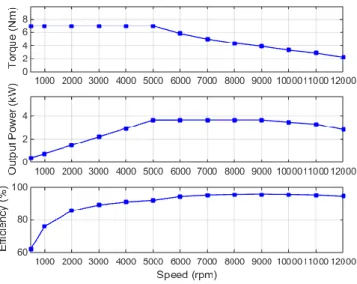
Figure 2. 30: Torque, power and efficiency of the WRSM ... 59
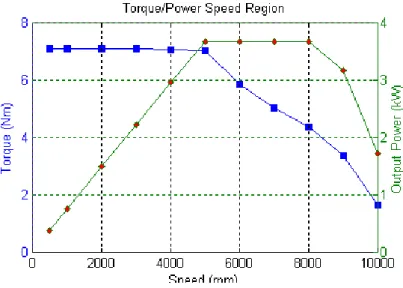
Figure 2. 31: Torque/power vs. speed of the WRSM ... 59
Figure 2. 32: Torque vs. speed of the SM-PMSM and WRSM ... 60
Figure 2. 33: Efficiency vs. speed of the SM-PMSM and WSRM ... 60
Figure 2. 34: Power vs. speed of the SM-PMSM and WRSM ... 61
Figure 2. 35: An example of one segment of the 11kW high speed PMSM ... 62
Figure 2. 36: Tooth winding coils wound on stator segments ... 62
Figure 2. 37: Cylindrical based WRSM ... 62
Figure 2. 38: Heptagonal based WRSM ... 62
Figure 3. 1: The cylindrical stator variables ...68
Figure 3. 2: The heptagonal stator variables ...68
Figure 3. 3: The geometrical variables of the rotor ...68
Figure 3. 4: Cylindrical stator of the WRSM ...69
Figure 3. 5: Heptagonal stator of the WRSM ...70
Figure 3. 6: 2D machines with NOMAD and fmincon codes ...76
Figure 3. 7: 3D machines with NOMAD and fmincon codes ...76
Figure 3. 8: Structure in 2D of the optimal WRSM ...80
Figure 3. 9: Magnetic induction of the optimal WRSM ...81
Figure 3. 10: Input currents for different phases of the optimal WRSM ...81
Figure 3. 11: Induced voltages for different phases of the optimal WRSM ...82
Figure 3. 12: Electromagnetic torque of the optimal WRSM ...82
Figure 3. 13: Optimal external volume with fixed machine length ...84
Figure 3. 14: Average torque in Optimization with L = 100mm ...85
Figure 3. 15: Torque ripple in Optimization with L = 100mm ...86
Figure 3. 16: Surface temperature in Optimization with L = 100mm ...86
Figure 3. 17: External volume in Optimization with L = 100mm ...87
Figure 4. 1: 3D structure of the optimal heptagonal based WRSM ... 92
Figure 4. 2: 3D electromagnetic torque of the rectified WRSM ... 93
Figure 4. 3: Electromagnetic torque obtained by 2D ANSYS Maxwell 15.1 ... 94
Figure 4. 4: Electromagnetic torque obtained by 2D ANSYS Maxwell 15.1 ... 95
Figure 4. 5: Electromagnetic torque analyzed by 3D ANSYS Maxwell 15.1 ... 95
Figure 4. 6: Electromagnetic torque analyzed by 3D ANSYS Maxwell 15.1 ... 96
Figure 4. 7: A closed volume within a finite region of flow ... 100
Figure 4. 8: Conversion of control volume in to small non-overlapping cells: Meshing ... 101
Figure 4. 9: Structured grid ... 101
Figure 4. 10: Unstructured grid ... 101
Figure 4. 11: Principal steps of CFD modelling ... 103
Figure 4. 12: Winding components ... 104
Figure 4. 13: Rotor modelling ... 105
Figure 4. 14: Stator modelling ... 105
Figure 4. 15: Orthogonal quality ... 106
Figure 4. 16: Skewness ... 106
Figure 4. 18: MRF interface of the simplified model ... 107
Figure 4. 19: Temperature distribution of the WRSM ... 109
Figure 4. 20: ‘zoom’ on the temperatures of the laminations ... 109
Figure 4. 21: One segment of the stator core ... 110
Figure 4. 22: “Pre-wound” stator winding ... 110
Figure 4. 23: Segmented stator core and rotor core ... 111
Figure 4. 24: WRSM prototype ... 111
Figure 4. 25: Rotor and stator ... 111
Figure 4. 26: Winding and insulation ... 111
Figure 4. 27: 3D electromagnetic torque of the prototype ... 113
Figure 4. 28: 3D induced voltage of phase A of the prototype ... 113
Figure 4. 29: EMF waveform in Oscilloscope ... 114
Figure 4. 30: EMF waveform by 3D FE analysis ... 114
Figure 4. 31: EMF comparison between experimental test and 3D FE analysis ... 115
Figure 4. 32: Experimental set-up for testing static torque without converters ... 115
Figure 4. 33: Measured static torque of the prototype ... 116
Figure 4. 34: Static torque in 3D FE analysis ... 116
Figure 4. 35: Static torque vs. rotor angle between experimental test and 3D FE analysis ... 117
List of tables
Table 1. 1: Efficiency comparison between WRSM and IPMSM ...10
Table 1. 2: Comparison between PMM, WRSM and IM ...11
Table 1. 3: Comparison of electrical motor technologies ...11
Table 2. 1: Comparison of double layer and single layer windings ...24
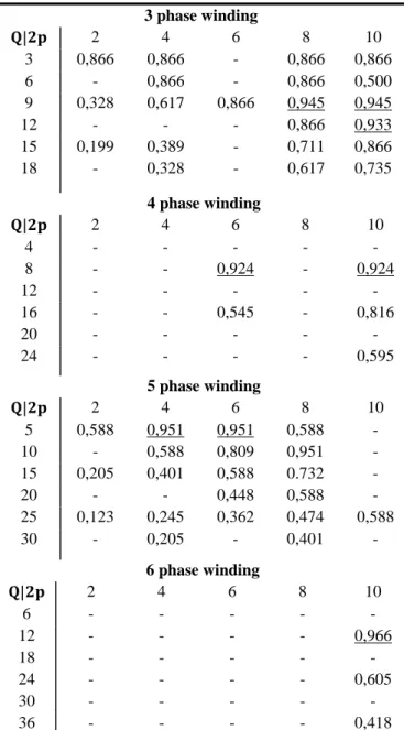
Table 2. 2: Fundamental winding factors of 3, 4, 5 and 6 phase windings ...33
Table 2. 3: Fundamental winding factors of multiphase windings ...35
Table 2. 4: Layouts of one coil side of selected phase/slot/pole combinations ...36
Table 2. 5: Additional losses for different types of machine ...46
Table 2. 6: Performances of the different WRSMs ...48
Table 2. 7: Performances of the different WRSMs ...50
Table 2. 8: SM-PMSM stator dimension ...51
Table 2. 9: SM-PMSM stator slot dimension ...51
Table 2. 10: SM-PMSM rotor dimension ...52
Table 2. 11: SM-PMSM stator winding parameters ...52
Table 2. 12: SM-PMSM performances ...53
Table 2. 13: WRSM stator dimension ...53
Table 2. 14: WRSM stator slot dimension ...54
Table 2. 15: WRSM rotor dimension ...55
Table 2. 16: WRSM stator winding parameters ...55
Table 2. 17: WRSM rotor winding parameters ...55
Table 2. 18: Machine performances of the designed WRSM ...56
Table 2. 19: Comparison performances between SM-PMSM and WRSM ...56
Table 2. 20: Performance comparisons between WRSM and SM-PMSM at specific speeds...61
Table 2. 21: Comparison of cylindrical and heptagonal based WRSMs ...63
Table 3. 1: Fixed parameters for the optimization ...69
Table 3. 2: Optimization constraints ...72
Table 3. 3: Optimal (local) solutions of (𝒫R1) problem ...74
Table 3. 4: Optimal solution of (𝒫R1) problem with fixed current densities ...75
Table 3. 5: Optimal (local) solution of (𝒫R2) problem ...75
Table 3. 6: Optimized variables of (𝒫R2) problem ...76
Table 3. 7: The bounds of optimization variables ...77
Table 3. 8: Effect of the parameters on the machine performances ...78
Table 3. 9: Optimal solution of (𝒫𝑅3) problem ...79
Table 3. 10: Optimized variables of (𝒫𝑅3) problem ...80
Table 3. 11: 2D performances of the optimal WRSM ...83
Table 3. 12: Optimal (local) results of (𝒫𝑅2𝑟) problem ...84
Table 3. 13: Optimal solution of (𝒫𝑅3) problem with 100 fixed machine length ...84
Table 3. 14: Optimal solutions for (𝒫𝑅3𝑟) problem with different fixed machine lengths ...88
xvi
Table 4. 1: 3D performances of the optimal WRSM ... 93
Table 4. 2: 3D machine performances of the corrected WRSM ... 94
Table 4. 3: Thermal properties of different materials at 20°C ... 105
Table 4. 4: Losses of different machine parts ... 108
Table 4. 5: Loss densities of different machine parts ... 108
Table 4. 6: Properties of the laminations ... 110
Table 4. 7: 3D performances of the prototype machine ... 112
Table 4. 8: DC values of armature currents in experimental test ... 116
Table 4. 9: DC values of armature currents in 3D FE analysis ... 116
General
introduction
The present thesis aims to the design optimization of a Modular Brushless Wound Rotor Synchronous Machine (MB-WRSM) for Heating, Ventilation and Air Conditioning (HVAC) application. Modular machine with integrated drive electronics has been widely investigated in many applications, particularly in embedded systems. Its advantage is the best compromise between fault tolerant capability and overall system cost. In this thesis, a multiphase modular machine based on the POKI-POKITM
structure developed by Mitsubishi Electric Cooperation is investigated.
In Chapter 1, a comparative study of different machine structures is presented. Rare-earth magnet machines are commonly used in many applications due to their high torque density and high efficiency. However, the price of rare-earth magnets rose significantly in the last years and the future world supply of these magnets may be restricted. Therefore, electrical machines without magnets are considered to replace permanent magnet machines in the future in which MB-WRSM is selected for our application. Firstly, it is important to list the advantages and the disadvantages of MB-WRSM compared to Permanent Magnet Synchronous Machines (PMSM). Though by comparison, the main features and important characteristics of MB-WRSM can be clearly specified. Additionally, the description of fault tolerance is indicated to illustrate the advantages of the modular machine and then, the special manufacturing technique for POKI-POKITM machine is also presented. In this introductory chapter, we
present a brief description of our optimization type and of two algorithms used for solving our design problem.
In Chapter 2, the description of non-overlapping fractional slot concentrated winding is shown. The goal of this part is to define winding construction and winding layout for different phase, slot and pole combinations. Fundamental winding factor will be calculated as a significant criterion in order to select the most appropriate winding configurations. Then, an electromagnetic model based on Finite Element (FE) method of a salient pole synchronous machine is described and the machine efficiency is calculated. With selected phase/slot/pole combinations, several machines will be analyzed and compared in order to select an appropriate machine in term of several criteria. Finally, the selected WRSM will be compared to a reference design Surface-Mounted Permanent Magnet Synchronous Machine (SM-PMSM) in order to evaluate its interest.
Chapter 3 proposes an optimization study of the chosen MB-WRSM to achieve the desired performances. Numerical optimization algorithms based on FE analysis are widely used to design electrical machines, especially with complex geometries. The advantage of these approaches is that they have high accuracy by taking into account nonlinear properties of the materials. However, the computational time is important. In this chapter, Quasi-Newton based algorithm using fmincon solver and Mesh Adaptive Direct Search (MADS) based algorithm using NOMAD solver are compared by
testing several numerical design problems. The selected algorithm will be employed for optimal design of a MB-WRSM.
Chapter 4 validates the optimal design results obtained by using 3D electromagnetic/thermal simulations and experimental tests. 3D FE simulations via ANSYS Maxwell is used in order to achieve electromagnetic performances more precisely by taking into account the effect of the end-winding zone. Besides, the machine temperature is verified by Computational Fluid Dynamics (CFD) method via ANSYS Fluent. Then, the constructed prototype is submitted to some tests and compared to 3D FE predictions.
Chapter 1
State of the Art of Modular Brushless
Wound Rotor Synchronous Machine
1.1 Comparison between Different Machines ... Erreur ! Signet non défini. 1.1.1 Rare-earth Permanent Magnet Synchronous Machine .... Erreur ! Signet non défini. 1.1.2 Alternatives to Rare-earth Magnets in Electrical MachinesErreur ! Signet non défini.
1.2 PMM and WRSM Performance Comparison ... Erreur ! Signet non défini. 1.3 Modular Brushless Machine ... Erreur ! Signet non défini. 1.3.1 Brushless Machine ... Erreur ! Signet non défini. 1.3.2 Modular Machine ... Erreur ! Signet non défini. 1.4 Optimization Methods for Machine Design ... Erreur ! Signet non défini. 1.4.1 Mathematical Optimization Formulations ... Erreur ! Signet non défini. 1.4.2 Optimization Algorithms (fmincon & NOMAD) ... Erreur ! Signet non défini. 1.5 Chapter conclusion ... Erreur ! Signet non défini.
1.1. Comparison between Different Machines 5 HVAC systems are typically the largest consumers of electrical energy in homes and office buildings. Saving energy needs to be considered due to the increase of recent environmental concerns. Since the power is mainly consumed by the motor used in the compressor so that the use of high efficiency and high torque density motors is an important issue for HVAC application. Nowadays, compressors for HVAC (an example is shown in Figure 1.1) frequently use PMSM because of its high torque density and high efficiency [1], [2]. However, the price of rare-earth magnet material such as NdFeB increases sharply and the rapid depletion of rare-earth magnet resources is an issue due to the future extensive use of the material in automotive drives, home appliance application and wind generators [4]. Therefore, other machines without rare-earth magnet material and high performance are considered to replace PMSM.
Figure 1. 1: LG compressor and permanent magnet motor
1.1
Comparison between Different Machines
The aim of the following study consists in investigating several electrical machines with high torque density, high efficiency and low cost for our application.
1.1.1 Rare-earth Permanent Magnet Synchronous Machine
PMSM is the best attractive motor in term of torque mass ratio and torque mass volume ratio. The PMSM has magnets mounted on the rotor and armature windings mounted on the stator. In fact, rare-earth magnet such as NdFeB generates a very strong magnetic field in a small volume and therefore, allow electrical machines to operate with very high torque density. Nevertheless, the use of PMSMs remains difficult to reach a significant constant power zone under good efficiency conditions, risk of demagnetization of the magnets at high temperature. Also, the loss of control of electronics at high speed operations may lead to high terminal voltages, which can become dangerous for the equipment. The
extensive use of rare-earth materials in a large number of applications can cause a strong exploitation of magnets and therefore, causes the sharply increase of the price. In 2011 and 2012, China, a country which has large rare-earth magnet resources, reportedly threatened to cut off international magnet supplies [3]. Moreover, recent sharp augmentation in the price of NdFeB magnets to more than 150 USD/kg is due to the increase areas of application [4].
PMSMs has two principle configurations with interior or surface magnets on the rotor. The position and the shape of the magnets can have a significant effect on the mechanical and electrical characteristics of the motor, especially on the inductances of the machine and the capability to operate on a wide range of speed at constant power.
Interior Permanent Magnet Synchronous Machine (refer to Figure 1.2)
Interior Permanent Magnet Synchronous Machines (IPMSMs) are built with magnets positioned inside the rotor. They are widely used in many variable speed applications which require wide flux-weakening operations such as electrical vehicles, domestic appliances [5]. One of the advantages of these machines is the torque generated by two components: one is generated by permanent magnet flux and the other by the rotor saliency. Besides, the rotor position can be detected without using a position sensor because of the anisotropic rotor [6]. However, due to the rotor structure, torque ripple and cogging torque which cause noise and vibration are critical problems in the IPMSM.
Figure 1. 2: Example of an interior permanent magnet synchronous machine
Surface-mounted Permanent Magnet Synchronous Machine (refer to Figure 1.3)
SM-PMSMs are constructed with magnets mounted on the surface of the outer periphery of the rotor. This configuration has several advantages such as easy manufacturing, higher remanent flux density and low torque ripple [7], [8]. However, the synchronous inductance of the machine is low such that it causes a high characteristic current and therefore, a low field weakening capability [9]. The mechanical robustness is lower than IPMSM due to high centrifugal forces. Therefore, it is not suitable for high speed applications without a sleeve which increases the air gap and decreases the torque. At slow speed,
1.1. Comparison between Different Machines 7
the use of a glass fiber bandage is enough to withstand these forces. Moreover, the torque is only produced by the interaction between the stator currents and the magnets because this machine has no saliency.
Figure 1. 3: Example of a surface-mounted permanent magnet synchronous machine
1.1.2 Alternatives to Rare-earth Magnets in Electrical Machines
Rare-earth permanent magnet machines are still the best solutions for high performance applications. However, for several applications, it may be not the best long-term solution due to the price spikes and the supply uncertainty of rare-earth magnets. Moreover, electrical machines with magnets are not efficient during a wide operating range. The exploitation of other electrical machines which do not have rare-earth magnetic materials are investigated. These machines are discussed in the following sections:
- Induction machine, - Reluctance machine,
- Wound rotor synchronous machine.
Induction machine
Induction machines (IMs) do not contain magnets and they are widely used in many industrial applications due to their low cost, high reliability, mechanical robustness and wide constant power range in generating mode. IMs operate by inducing electrical currents in the rotor. Thus, the losses in the rotor are significant, which can cause total losses typically two or three times higher than in a PMSM [10]. The efficiency of these machines is thus lower than other machines and they may quickly become overheated. It is much more difficult to cool the rotating rotor than the stationary stator due to high losses occurred in the rotor. The biggest drawback of the IM is the lagging power factor.
Improvements can be obtained through the use of squirrel cage rotor and therefore, nowadays most IMs used are the squirrel cage machine shown in Figure 1.4. Rotor conducting bars usually use aluminum or copper. They are connected together with an end ring to form a closed electric circuit and a slightly skewed to the axis of the rotor for reducing the cogging torque. Copper cage IMs have been utilized in HEV and EV such as Renault Kangoo, Chevrolet, Silverado, Daimler Chrysler Durango and BMW 5
[33]. They improve efficiency and reduce temperature rising during the operation. However, the manufacturing cost of the cooper rotor cages can be higher [11].
Figure 1. 4: Example of a squirrel cage induction machine
Reluctance machine
The generation of reluctance torque is produced by rotor saliency with non-isotropic magnetic reluctance that interacts with a stator magneto-motive force. There are two types of reluctance machines as:
Synchronous reluctance machine, Switch reluctance machine.
Switched Reluctance Machines (SRMs) represented in Figure 1.5 do not contain PMs. They have a number of benefits such as robust structure, low cost and operating at high temperatures. Nevertheless, their disadvantages are complex control, high torque ripple and acoustic noise [12], [13].
Figure 1. 5: Example of a switched reluctance machine
Like SRMs, Synchronous Reluctance Machines (SynRMs) shown in Figure 1.6 have no magnet. The SynRM conventionally uses a stator very similar to that used in an IM and a PMSM. This stator is
1.1. Comparison between Different Machines 9
excited by sinusoidal currents to create a rotating field. The rotor which contains neither magnets nor copper winding is salient, offering a low reluctance in one axis and a high reluctance in the other axis. It allows the machine to lock synchronously onto the rotating stator field. The SynRM have a high efficiency due to the absence of the Joule losses in the rotor. However, the machine has several main problems such as a moderate torque density (SynRM < PMSM), a low power factor and a reduced field weakening zone [10].
Figure 1. 6: Example of a synchronous reluctance machine
Wound rotor synchronous machine
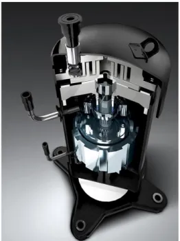
Wound Rotor Synchronous Machines (WRSMs) shown in Figure 1.7 are widely used in electrical power generation worldwide at high power levels with high efficiency and reliability. WRSMs have several advantages including a low cost, a wide field weakening region at high speed and a significant improvement of the safety thanks to the possibility of canceling of the field current, and therefore, this limits the risks of high voltages for high speed operation [14], [18]-[22] which match well with the requirements of HVAC applications. However, the rotor windings cause Joule losses, and it is difficult to evacuate the heat. Additionally, the torque density of WRSM is usually lower than that of PMSM.
Moreover, the stator is fed with sinusoidal currents to generate AC rotating field, while the rotor contains copper windings which are excited by a DC current to set up a magnetic field. It is necessary to have a mechanism for passing current from the stationary part to the rotating part of the machine. The brushes and the slip rings can be thus required to supply the field current, leading to maintenance issues.
Figure 1. 7: Example of a wound rotor synchronous machine
Unfortunately, a perfect machine does not exist. The selection of a machine structure is always a compromise between the specifications of the application and the specificities of the partner company in terms of manufacturing cost, power density, machine efficiency and control strategies. In our study, MB-WRSMs are selected to be investigated; these machines have several advantages such as low cost, wide field weakening region, high fault tolerant capability, etc. In order to validate the relevance of this choice against Permanent Magnet Machine (PMM) which are widely used across a wide range of applications, a small comparative study will be conducted in the next section.
1.2
PMM and WRSM Performance Comparison
In order to replace PMMs in HVAC application, the torque density and the efficiency are a key issue to find an appropriate machine without magnet. Here, some comparisons between the WRSM and others machines are listed, especially PMM. The efficiency comparisons between the WRSM and the IPMSM in [15] is indicated in Table 1.1.
Table 1. 1: Efficiency comparison between WRSM and IPMSM Torque (Nm) Power (W) Armature Current (A) Field Current (A) Line Voltage rms (V) Power Factor Efficiency (%) 2150rpm WRSM 18 4053 68.2 2.0 48.1 0.828 80.2% IPMSM 18 4053 60.5 - 50.7 0.877 87.1% 9000rpm WRSM 4.30 4053 34.02 1.1 77.25 0.975 89.72% IPMSM 4.30 4053 43.2 - 77.30 0.852 84.50%
1.2. PMM and WRSM Performance Comparison 11
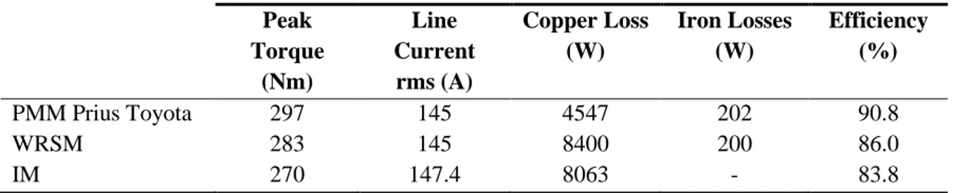
Note that the WRSM operates efficiently at high speed, due to an easier field weakening control. In Table 1.2, the comparison among the WRSM derived from the Prius IPM with different sizes of rotor and Prius Toyota PMM, IM at 1500 rpm in [16] are shown.
Table 1. 2: Comparison between PMM, WRSM and IM Peak Torque (Nm) Line Current rms (A) Copper Loss (W) Iron Losses (W) Efficiency (%) PMM Prius Toyota 297 145 4547 202 90.8 WRSM 283 145 8400 200 86.0 IM 270 147.4 8063 - 83.8
Note that the efficiency of WRSM seems significantly lower than PMM at low speed due to higher copper losses.
The efficiency, cost comparison among different types of machine such as NdFeB magnet machine, ferrite PMM, WRSM, IM, and SRM in [10] is displayed in Table 1.3.
Table 1. 3: Comparison of electrical motor technologies Peak power (kW) Efficiency (%) Torque density (Nm/kg) Active material cost ($) Active material cost per kW ($/kW)
Reduced NdFeB Magnet M 80 98 15 223 2.78
Ferrite PMM 80 96 11 154 1.93
WRSM 50 96 10 144 2.88
Copper rotor IM 50 96 10 144 2.88
SRM 75 97 15 118 1.57
Note that the torque density of the WRSM is lower than that of the PMM. Although the price of active material cost of the WRSM is smaller than that of PMM, the active material cost per kW of the WRSM is higher than PMM.
Indeed, the WRSM and PMSM have the similar stator; however, the rotor of WRSM contains the winding and of PMM contains the magnets. The main drawbacks of WRSM compared to PMSM are a lower torque density and a lower efficiency at low speed due to losses in the rotor winding. Additionally, the slip ring and brushes require frequent maintenance, having a high copper loss, etc. In order to overcome this issue, a brushless system is implemented for the rotor field excitation [17]. Moreover, with the development of power converters, the modular model is proposed to increase fault tolerant capability which is an important requirement of embedded systems.
MB-WRSM can be a good candidate for embedded systems in which significant fault tolerant capability is required if its performances can be improved on the following points:
- Increase of the efficiency.
Consequently, the MB-WRSM will be investigated with the objective to achieve high performances.
1.3
Modular Brushless Machine
1.3.1 Brushless Machine
Brushes and slip rings showed in Figure 1.8 which are usually used to excite the field current of WRSM is a demanding problem. Its disadvantages are losses, maintenance and debris issues.
Figure 1. 8: Brush excitation [35]
In this study, a brushless system with a rotary transformer which have successfully demonstrated system efficiency > 90% with a lower lifetime cost is used. It causes lower frictional losses, and an easier maintenance compared to a brush system. A rotary transformer shown in Figure 1.9 is a transformer with an axial symmetry and an air-gap between the primary side and the secondary side. The air-gap allows the rotation of one half of the core, without influencing the flux lines and the inductive power transfer between the primary and secondary side [34].
1.3. Modular Brushless Machine 13
1.3.2 Modular Machine
1.3.2.1 Fault tolerant capabilityFault tolerance of a system is a key issue in embedded systems. Safety must be considered in the event of a failure into the system. As consequence of the failure, some damages of the equipment and danger for the system operators can occur [23]. In WRSM drives, several faults, both in the machine and in the power converter must be considered. [24], [25] show many potential faults that can occur in electrical machines such as:
- Winding open circuit,
- Winding short circuit: phase to phase, phase to ground, turn to turn, - Short circuit at the machine terminals.
Phase to phase short circuit faults are among the most common faults in AC machine. The combination of the above faults can occur because they tend to be cumulative and therefore, one fault induces other faults. Here, a modular system is proposed in order to prevent this type of short circuit.
The use of modular machine drive increases the redundancy and improves reliability of the system [29]-[31]. The integration of the drive electronics into the housing of the machine shown in Figure 1.10 has been widely investigated in a wide range of applications [26].
Figure 1. 10: Single phase modular configuration
Integration of the machine and drive has several advantages in [27], [28] as: - Reduction of the total drive volume and weight,
- Elimination of interconnects and reduce the risks of generating high voltage transients on the winding.
However, the use of integrated motor drive can cause an increase of losses and therefore, of the temperature.
In this study, each phase of the machine is connected to a separate single-phase converter (see Figure 1.11). Each phase drive module is considered as a single module and every phase can operate independently of the others. These structures are highly redundant and the effects on the other phases are minimized in case of having fault at one phase. It means that the system is well able to continue the operation when a fault occurs.
Figure 1. 11: Integrated machine and power supply concept
1.3.2.2 Multiphase machine
The multiphase machine has recently become a competitive candidate for safety critical applications due to its enhanced fault tolerant capacity compared to a conventional three-phase machine. The higher number of phases increases the number of freedom degrees for the machine supply which is used to achieve a better performance and a higher fault tolerance. There are several considerable benefits from the use of multiphase machines [23], including:
- Improved fault tolerant behavior
Multiphase machine has an improved fault tolerant capability because more phases can provide partial retention of functionality even in the eventuality of a power component die.
- Reduced phase current
In a multiphase AC drive, the phase current can be reduced without increasing the voltage per phase since the power is evenly divided among a larger number of phases. This reduces the size and the power rating of the individual power semiconductor switches.
- Improved armature magneto-motive force waveform
Multiphase machines can improve Magneto-Motive Force (MMF) waveforms. The reduction in the armature air-gap MMF harmonic components has several advantages such as the torque ripple reduced, acoustic noise reduced and lower rotor losses.
1.3. Modular Brushless Machine 15
Nevertheless, the multiphase machine has several drawbacks such as:
- Higher number of power semiconductor switches are needed. It can increase the volume, the weight and the cost of the power converter, leading to a higher complexity and possibly to a lower reliability of the overall system,
- Non fundamental harmonics of the current must be considered by the control.
Finally, the increase in the number of phases could finally make the whole system more complex and expensive. However, it increases the fault tolerant capability as well as better reliability.
1.3.2.3 Stator segmentation
An interesting concept for achieving higher modularity in the machine is the segmentation in the stator core. For this structure, high fault tolerant capability can be achieved due to physical separations. These advantages are presented in [26]. Indeed, the faulty components can be replaced quickly and cheaper. Moreover, the copper slot fill factor is higher and the machine can be wound automatically. One of different types of the segmented stator is a ‘T-core’ segment as shown in Figures 1.12 and 1.13.
Figure 1. 12: Stator segmentation Figure 1. 13: Modular motor in LG compressor
Mitsubishi Electric Corporation developed this type of machine called POKI-POKITM shown in Figure
1.14. The stator slots are fully open (e.g. the teeth have no tip) and therefore, it is easier to pre-wind the coil for each segment of the stator core with non-overlapping concentrated winding. After the coils are wound, the stator is formed into a cylindrical shape and is press fitted into a frame. Its advantages are the modularity, the fast automatic winding manufacturing, the easiness to assemble and to remove, and therefore, it is easier to replace faulted components and this simplifies the connections in the machine. Moreover, the slot fill factor can be increased, leading to a decrease of copper losses [32]. It should be noticed that the POKI-POKITM machine is only suitable for short active length due to the mechanical
Figure 1. 14: Modular structure of POKI-POKITM machine [32]
1.4
Optimization Methods for Machine Design
1.4.1 Mathematical Optimization Formulations
Everything in our daily life needs to be optimized in order to look for a better solution. Especially, optimization is an important tool in science and industry. Since 1980, with the increasingly need of electrical machines, design optimization methods which solve problems about machine weight, volume, cost and efficiency have been developed. The goal of optimization methods is to find the values of the variables that minimizes or maximizes an objective function subject to several constraints.
Generally, mathematical optimization problems involve continuous and integer variables and twice differentiable functions. However, from different domains of physics, design problems have to be formulated by considering some integer variables yielding Mixed-Integer Non-Linear Programs (MINLP): { min x∈ℝn,z∈ℕmf(x, z) Under constraints: gi(x, z) ≤ 0 ∀i ∈ {1, … , p} hj(x, z) = 0 ∀j ∈ {1, … , q} (1.1)
Where: 𝑥 is the vector of variables, 𝑓 is the objective function, 𝑔𝑖 are the inequality constraints and ℎ𝑗
are the equality ones.
The objective and the constraint functions depend on continuous and integer variables. Generally, the design of electrical machines has this formulation and several different algorithms can be used and developed to solve this mixed-integer non-linear optimization problem. Examples of applications for solving the MINLP can be found in [36]-[41]. [36] presented the optimization problem of designing electromagnetic actuators with many types of variables such as real, integer, categorical and logical variables; e.g. categorical variables are used to characterize materials.
1.4. Optimization Methods for Machine Design 17
Actually, several optimization algorithms need some information about the derivatives of the functions and also an explicit analytical formulation of them. Several examples in [36], [42] and [43] described the optimization problem using analytical models for electrical machines, actuators. In this case, efficient deterministic global algorithm, named IBBA (an exact global optimization method based on an interval Branch and Bound technique) is used. Several stochastic algorithms like Genetic Algorithms can also be used to solve problems of type (1.1), see [44]-[46].
The multiphase salient pole WRSM owns a complicated structure. To develop analytical models, normally, we must simplify the machine geometry and linearize the magnetic properties by using some form of equivalent permeability. Nowadays, obtaining an accurate analytical model for salient pole WRSM design is a really challenging task. Considering that, one of the solution is to use numerical models based on FE method. Indeed, with the development of computer technology, the design of electrical machines using numerical simulations has been widely used because they are able to take both saturation and complicated geometry into account. One of the drawbacks with the numerical simulation is the computation of the derivatives which is very expensive in CPU time (finite difference method). This leads to the idea that achieving the global minimum of the problem MINLP (Equation (1.1)) seems to be unreachable. Thus, in this thesis we focus on the search of local minimums by trying to find the best possible one. Moreover, in order to investigate a complete design problem formulated as a MINLP, all of our calculations which are carried out by numerical simulations via FE code appears to be very difficult at this stage. Hence, the interesting structures of the WRSM are previously studied in Chapter 2 and the most efficient structure is selected. This allows us to consider a continuous optimization problem where the functions are performed via a FE code. The optimization problems that we study in this thesis are:
{ min 𝑥∈ℝ𝑛𝑓(𝑥) 𝑈𝑛𝑑𝑒𝑟 𝑐𝑜𝑛𝑠𝑡𝑟𝑎𝑖𝑛𝑡𝑠: 𝑔𝑖(𝑥) ≤ 0 ∀𝑖 ∈ {1, … , 𝑝} ℎ𝑗(𝑥) = 0 ∀𝑗 ∈ {1, … , 𝑞} 𝑎𝑖 ≤ 𝑥𝑖≤ 𝑏𝑖 (1.2)
The design of electrical machines including electromagnetic, mechanical and thermal requirements should be considered in the optimization. This makes the composition of an electrical machine more complex. Using efficient tools is thus necessary in order to obtain good solutions. Within the past decade, many optimization algorithms have been investigated for the design of electrical machines [36], [45]. The algorithms are evaluated and compared in order to find efficient solutions for the applied optimization problems. Therefore, the choice of the algorithm is an important task because it may determine whether the problem is solved rapidly or slowly and whether the solutions are good or not. In the next subsection, we present the two optimization algorithms we use in this thesis.
1.4.2 Optimization Algorithms (fmincon & NOMAD)
The two different optimization algorithms used on this thesis are: Quasi-Newton based algorithm and MADS based algorithm. The Quasi-Newton based algorithms are implemented in the fmincon routine
of Matlab, it is a gradient based method [47]-[49]. In contrary, NOMAD solver based on MADS method does not use derivative computations [50]-[52].
The main difference between these two optimization algorithms is the computations or not of the derivatives, else they use the same iterative following steps:
𝑥[𝑘+1]: = 𝑥[𝑘]+ 𝑑[𝑘] (1.3)
Where: 𝑥[𝑘], 𝑥[𝑘+1] is the vector variable at 𝑘, 𝑘 + 1 optimization iteration, 𝑑[𝑘] is a direction of descent;
e.g. a direction which makes it possible to assure the convergence of a suite of point 𝑥[𝑘] to a local optimal solution.
Thus, these two optimization methods always require a starting point 𝑥[0] which is a key issue in the convergence of those algorithms. Based on that, the two algorithms search for the next point by determining 𝑑[𝑘]; the computation of 𝑑[𝑘] is the main difference between local optimization algorithms.
fmincon code
Quasi-Newton based algorithms which are widely used to optimize the design of electrical machines. It can solve nonlinear constrained problems of type (1.2) based on the computations of derivatives of the objective function and of the constraints. fmincon solver which is based on Quasi-Newton updating method is available in Matlab Toolbox. It requires a gradient to define a search direction and calculate the search distance in which the Hessian of Lagrangian function is approximated by updating at each iteration thanks to the function values and gradients from previous iterations [48]-[49].
The basic form of the use of this Matlab routine is:
𝑋 = 𝑓𝑚𝑖𝑛𝑐𝑜𝑛(𝐹𝑜𝑛𝑐𝑂𝑏𝑗, 𝑥𝑜, 𝐴, 𝑏, 𝐴𝑒𝑞, 𝑏𝑒𝑞, 𝑙𝑏, 𝑢𝑏, 𝐶𝑜𝑛𝑡, 𝑜𝑝𝑡𝑖𝑜𝑛) (1.4)
Where: 𝑋 is the optimal solution, 𝐹𝑜𝑛𝑐𝑂𝑏𝑗 is the objective function, 𝑥𝑜 is the starting point, 𝐴, 𝑏 are the
inequality constraint 𝐴𝑥 < 𝑏, 𝐴𝑒𝑞, 𝑏𝑒𝑞 are the equality constraint 𝐴𝑒𝑞𝑥 = 𝑏𝑒𝑞, , 𝑙𝑏 and 𝑢𝑏 are the
interior and exterior bounds of the variables, 𝐶𝑜𝑛𝑡 is the constraint function, 𝑜𝑝𝑡𝑖𝑜𝑛 is the selected algorithm.
Active-set, sqp and interior-point optimization algorithms can be selected in the fmincon routine. These algorithms differs also on the way to compute the descent direction 𝑑[𝑘], for details on these algorithms
see [47].
NOMAD code
NOMAD solver which is available in Matlab Toolbox can solve nonlinear constrained problems of type (1.2). It is well suited to solve black-box optimization (where the function or/and the constraints are computed via a numerical code) [50], [51]. Its architecture is shown in Figure 1.15 where the objective function and/or constraints could be computed via the use of numerical simulations (non-accessible information). Actually, NOMAD can be used when:
1.4. Optimization Methods for Machine Design 19
- There is no access to the derivative,
- The evaluation of the function may be polluted by noise,
- The evaluation of the objective function may fail even on admissible points.
Figure 1. 15: NOMAD solves black-box problem [50]
MADS is a kind of the local direct search method, it is proved that NOMAD converge to a local solution [53]-[56]. It includes the search step and the poll step. At each search step, trial points are generated on the mesh using a mesh size parameter. At the poll step, random points are chosen among mesh points in the frame with a poll size parameter. For the current solution (found at iteration 𝑘 of the algorithm), the frame center is the center of a mesh. When an improved solution is located in the neighborhood, it becomes a new frame center. A frame is regenerated from this new frame center. The mesh size shown in Figure 1.16 is controlled to look for a solution. It can be increased for successful searches and decreased for unsuccessful searches. When the mesh size is inferior to a tolerance value, an optimal solution can be obtained and the search is terminated.
Figure 1. 16: An example for explaining NOMAD algorithm [51]
NOMAD can also use surrogate functions [57] instead of the real objective function for the poll step and use the real objective function only to check the accuracy of the value found (Figure 1.17). In this way, test points are evaluated through the substitute function (which is easier and more rapidly computed) and so, most promising points are evaluated by the real objective function. This makes it possible to explore the search space better and reduce the computational time.
Figure 1. 17: Substitute model can be used in NOMAD [57]
1.5
Chapter conclusion
The machine in the compressor of HVAC system often use expensive rare-earth permanent magnet materials, but manufacturers are keen to develop drive machines without magnet. The different types of electrical machines have been reviewed with theirs advantages and drawbacks. Based on that, we justified the choice to study a MB-WRSM used for our HAVC application. This machine has no rare-earth magnet material and needs to reach the high performance that PMSM provides. In order to achieve a high performance WRSM as best as possible, optimization methods are key issues in our study. Therefore, optimization is presented and the two algorithms which are used in this thesis, are detailed at the end of this chapter.
Indeed, the key issue of machines without magnet is the torque density and the efficiency. Therefore, in the next chapter, a precise study of the WRSM is conducted to determine the structure which is the most interesting one. Moreover, this structure is then compared to a reference design SM-PMSM in order to evaluate its potential for the application.
Chapter 2
Choice of WRSM Structure
2.1 Fractional Slot Concentrated Winding ... 23 2.2 Phase, Slot and Pole Combination ... 25 2.2.1 Cros’ method ... 26 2.2.2 Star of Slots ... 29 2.2.3 Winding Factor Results ... 32 2.3 WRSM Performance Comparisons ... 36 2.3.1 2D Finite Element Design ... 36 2.3.2 Loss and Efficiency Computation ... 43 2.3.3 Selection of an Appropriate WRSM ... 46 2.4 WRSM and SM-PMSM Comparison ... 51 2.4.1 SM-PMSM Design ... 51 2.4.2 WRSM Design ... 53 2.4.3 Torque Speed Characteristics ... 57 2.5 Heptagonal based WRSM ... 61 2.6 Chapter conclusion ... 63
2.1. Fractional Slot Concentrated Winding 23
FE analysis becomes more popular in the field of electrical machine design since analytical equations are not easily formalized for the machines which have complicate structures. Using electromagnetic analysis, we comparatively study different WRSMs and therefore, select the structure which offers the best fault tolerant capability and the highest output performances. For this propose, firstly, the winding characteristics and the numbers of phases, slots and poles must be selected. With suitable winding configurations, several machines are analyzed by using 2D FE simulations which allows us to compute the machine performances. According to the torque density, the torque ripple and the machine efficiency, an appropriate machine is chosen and then compared to a reference design SM-PMSM in order to evaluate the interesting performance features of the WRSM.
2.1
Fractional Slot Concentrated Winding
Fractional Slot Concentrated Winding (FSCW) machines have been widely investigated for many applications. They are well suited for fault tolerant applications [58]. Several advantages of employing a FSCW are listed in [59] - [61] as:
- Higher copper slot fill factor if coupled with segmented stator structures, - Short end-winding and therefore, copper losses can be reduced,
- Suitable for automatic manufacturing and reduced manufacturing costs in modular designs, - A high leakage inductance and a low mutual inductance, leading to the improvement of the flux
weakening capabilities,
- The contact among the phases is reduced due to high leakage inductance and low mutual coupling among the phases. It is an interesting solution for fault tolerant applications.
Considering the thermal aspect of the machine, FSCW ensures physical and magnetic isolation is maintained to increase fault tolerant capability [63]:
- Physical insulation: In concentrated windings, the coils are wound around a single tooth, and there is non-overlapping between phases. Thus, the electric fault between machine phases is limited in this phase. In double layer winding machines, a separator between coil sides may be required in order to guarantee the insulation between phase windings.
- Magnetic insulation: A high linkage inductance can limit the short-circuit currents. Moreover, a low mutual inductance among the phases enables preventing the impact of one phase on other phases.
Nevertheless, the use of FSCWs can lead to undesirable effects such as eddy current losses, torque ripple, acoustic noise and vibration due to an increase in the harmonic content of MMF waveform [62].
2.1.1 Number of winding layers
Figure 2.1 illustrates both type of windings: double layers and single layer. Single layer windings have coils wound only on alternate teeth, whereas each tooth of the double layer windings carries a coil. The selection of number of layers is based on the characteristics of the machine which is suited for a particular application.
Figure 2. 1: Double layer and single layer windings [59]
Table 2.1 presented in [59] indicates the comparison of double layer windings and single layer windings.
Table 2. 1: Comparison of double layer and single layer windings
Double layer windings Single layer windings
Difference of coils/slot 2 1
Mutual phase coupling Significant phase-phase coupling through mutual slot leakage
Very low mutual phase coupling
End turns Shorter end turns Longer end turns
Phase inductance Lower phase inductance due to lower phase leakage inductance
Higher phase inductance due to higher phase leakage inductance
Rotor losses
Lower rotor losses mainly due to lower fundamental stator MMF
space harmonic component
Higher rotor losses mainly due to higher fundamental stator
MMF space harmonic component Slot/pole combination Many slot/pole combinations
possibility
Few slot/pole combinations possibility
Ease of manufacturing More difficult Easier
Synchronous winding factor Lower Higher
Back electromotive force More sinusoidal Less sinusoidal
The double layer FSCWs shown in Figure 2.2 can cause lower rotor losses, torque ripple, vibration and noise due to the lower air-gap MMF harmonic content compared to the single layer FSCWs. Nevertheless, in the single layer, physical separation between phases is better and the phase inductance is higher. This makes it possible to improve thermal issues and fault tolerant capability. In this study, torque density, machine efficiency and torque ripple are the important requirements so that double layer winding seems to be more appropriated.
2.2. Phase, Slot and Pole Combination 25
Figure 2. 2: An example of double layer concentrated winding [64]
Besides, the open slot type is selected because of the advantage of permitting easy installation of form wound coils and their easy removal in case of repair. Nevertheless, its drawback is that the air-gap flux can be distributed into bunches or tufts, and therefore, the ripples can be produced in the wave of generated Electro-Motive Force (EMF) and electromagnetic torque.
2.2
Phase, Slot and Pole Combination
Winding factor plays an important role in the torque production. The winding factor for the main harmonic should be as high as possible in order to maximize the EMF and consequently the average torque of the machine. In case of low fundamental winding factor, the stator winding needs to be fed with higher currents in order to generate the same torque compared to the machine with higher fundamental winding factor. Considering that the winding factor depends on slot and pole combination as well as winding layout, the selection of phase, slot and pole combination is thus a critical issue in order to maximize the fundamental winding factor.
In general, AC machine windings can be classified according to the number of slots per pole per phase (𝑞). The windings are distributed when 𝑞 ≥ 1. And the windings are concentrated when 𝑞 ≤ 1. When 𝑞 is not an integer, the winding is a fractional slot winding. Otherwise, it is referred to as integral slot winding. Additionally, there are a set of rules for the pole and slot combinations that makes non-overlapping windings valid [65]:
- The number of poles must be even,
- The number of slots must be a multiple of the number of phases, - The number of coils and slots are equal in double layer windings, - The number of slots cannot be equal to the number of poles.
The various combinations of phase, slot and pole numbers which enable achieving a balanced winding can be determined by the following condition:
𝑄
Where: 𝑄 is the number of slots, 𝑝 is the number of pole pairs, 𝑚 is the number of phases and 𝑘 is an integer number.
For a specific slot/pole combination and number of phases, there are many possibilities to arrange the coils of each phase in the slots to form the winding layout. For non-overlapping double layer FSCW, the fundamental winding factor can be calculated by different methods: Cros’ method and Star of Slots.
2.2.1 Cros’ method
The Cros’ method based on EMF phasors consists in defining the winding layout of double layer FSCW which makes it possible to maximize the fundamental winding factor of the fundamental EMF. This method was investigated by some authors [65]-[67]. A review of these papers is presented in this part.
The number of slots per pole per phase 𝑞 must be defined in its most simplified fraction. For values below unity, 𝑞 must be reduced to a fraction of two non-divisible integers (𝑏 and 𝑐) as:
𝑞 = 𝑏/𝑐 (2.2)
A one-zero sequence can be established thanks to this equation. The number of “1” in the sequence is equal to 𝑏, and the number of “0” is equal to 𝑐 - 𝑏. For a given structure, the winding with the highest fundamental winding factor can be obtained by the most regular distribution of the number “1” among the numbers “0”. The structure of the whole winding can be determined in five steps:
- In a first step, the one-zero sequence created is based on the number of slots per pole per phase. - The sequence is repeated 𝑄/𝑏 times.
- The usual phase sequence (e.g. AC’BA’CB’ for a three-phase machine) is assigned to the aforementioned number sequence (A’ characterizes the return conductor corresponding to conductor A).
- The conductors corresponding to the numbers “1” are selected to make the first layer of the double layer winding.
- The second layer of the winding is obtained by shifting the first layer in the other side of the tooth and reversing the phase direction.
The final winding layout of one phase is created. This layout is described by a vector 𝑆 which contains the number of filled slots. For each slot which contains the conductor of the phase A, the number of the slot with the sign of the phase is written in 𝑆. If the two layers of one slot contains phase A, then the number of the slot is A’. For the conductor A’, a minus is added to the corresponding slot numbers. The last step is essentially used to calculate the fundamental winding factor for double layer windings. The vector 𝑆 is used to obtain the EMF phasor 𝐸𝑖 of conductor 𝑖 from the one phase for the main harmonic
rank of 𝑝 or the fundamental is represented as:
𝐸𝑖
⃗⃗⃗ = 𝑠𝑖𝑔𝑛(𝑆(𝑖))𝑒𝑗𝜋×2𝑝|𝑆(𝑖)⃗⃗⃗⃗⃗⃗⃗⃗ /𝑄|
. (2.3)

![Table 2.1 presented in [59] indicates the comparison of double layer windings and single layer windings](https://thumb-eu.123doks.com/thumbv2/123doknet/3006575.84415/42.892.84.788.427.844/table-presented-indicates-comparison-double-windings-single-windings.webp)