HAL Id: pastel-00751668
https://pastel.archives-ouvertes.fr/pastel-00751668
Submitted on 14 Nov 2012HAL is a multi-disciplinary open access archive for the deposit and dissemination of sci-entific research documents, whether they are pub-lished or not. The documents may come from teaching and research institutions in France or abroad, or from public or private research centers.
L’archive ouverte pluridisciplinaire HAL, est destinée au dépôt et à la diffusion de documents scientifiques de niveau recherche, publiés ou non, émanant des établissements d’enseignement et de recherche français ou étrangers, des laboratoires publics ou privés.
Etude des mécanismes de génération des stries dans le
procédé de découpe laser d’aciers
Koji Hirano
To cite this version:
Koji Hirano. Etude des mécanismes de génération des stries dans le procédé de découpe laser d’aciers. Mécanique [physics.med-ph]. Arts et Métiers ParisTech, 2012. Français. �pastel-00751668�
N°: 2009 ENAM XXXX
Arts et Métiers ParisTech - Centre de Paris
2012-ENAM-0029
École doctorale n° 432 : SMI, Sciences des Métiers de l’Ingénieur
présentée et soutenue publiquement par
Koji HIRANO
le 14 Septembre 2012
Study on striation generation process during laser cutting of steel
Doctorat ParisTech
T H È S E
pour obtenir le grade de docteur délivré par
l’École Nationale Supérieure d'Arts et Métiers
Spécialité “ Mécanique - Matériaux ”
Directeur de thèse : Rémy FABBRO
T
H
È
S
E
JuryMme Simone MATTEI, Professeur, Université de Bourgogne Rapporteur
M. Alexander KAPLAN, Professeur, Université de Lulea, Suède Rapporteur
M. Marc MEDALE, Professeur, Université Aix-Marseille Examinateur
M. El-Hachemi AMARA, Directeur de recherche, CDTA, Algérie Examinateur
M. Francis BRIAND, Expert Procédés, Air Liquide Welding Examinateur
Acknowledgments
First of all, I would like to thank the PIMM Laboratory at Arts et Métiers ParisTech and the Directors, M. Thierry BRETHEAU and M. Gilles REGNIER, who welcomed me to the laboratory for this PhD study.
I express my heartfelt thanks to the supervisor of this thesis, Rémy FABBRO (CNRS/Arts et Métiers ParisTech). Tremendous hours of discussion with him lead to important and original results of this study. Many fruitful ideas, suggestions, and sometimes critical comments, which were issued from his vast knowledge and experience, helped navigate this study in proper direction. I am sure that this three years’ experience will also be really helpful for my ongoing career as a researcher.
I would like to thank Nippon Steel Corporation and relevant members who gave me this chance to study at Arts et Métiers ParisTech. I am really grateful to the company not only for the financial support to this research but also for constant cares during my two years’ stay in Paris from 2009 to 2011.
It is a great honour for me that Prof. Simone MATTEI (University of Burgundy) and Prof. Alexander KAPLAN (Luleå University of Technology) accepted to read my thesis and to make a report as jury members of the defence. I am quite grateful to Prof. Marc MEDALE (Polytech' Marseille), Dr. El-Hachemi AMARA (Centre for Development of Advanced Technologies) and Dr. Francis BRIAND (Air Liquid Welding) for participating in the jury and examining my dissertation.
I would like to give my great thanks to Frédéric COSTE for his support in various experiments at the disc laser platform in PIMM. I am grateful also to other members of the laser team: Maryse MULLER, Matthieu SCHNEIDER, Kevin VERDIER, Corinne DUPUY, Emilie LE GUEN, Mariette NIVARD and Cyril GORNY, who supported me in preparing experimental instruments, operating experiments and analysing samples.
I deeply thank Dr. Francis BRIAND and his colleagues at Air Liquid Welding for performing an important comparative laser cutting experiment with their fibre and CO2 lasers. My special thanks go
to Petr YUDIN (Khristianovich Institute of Theoretical and Applied Mechanics; now at École Polytechnique Fédérale de Lausanne) for valuable discussion and instruction on visualisation technique of melt film dynamics on kerf fronts. I express my gratitude to Shun KOJIMA (PHOTRON LTD.) for technical support for use of a high speed video camera. I would like to give my sincere thanks to Dr. Laurent Limat (CNRA/Paris Diderot University) and his team members for useful discussion and their comments on dynamics of melt accumulations on kerf sides. I also convey my thanks to Dr. Ken-ichi Sugioka (Tohoku University) for helpful comments and advice for some aspects of fluid mechanics.
I would like to express my gratitude to those who helped me begin and perform numerical simulations: Prof. Marc MEDALE (Polytech' Marseille), Dr. Partick NAMY (SIMTEC), support team members at COMSOL France, Dr. Charline TOUVREY (CEA), and Maxim TROSHIN (Tomsk Polytechnic University). Although I could not include many results of numerical simulations in this thesis, their valuable support will serve me to develop this study further in terms of numerical simulations.
Members in Nippon Steel Corporation also helped me conduct this study. I am thankful to Hirofumi IMAI for discussion on experimental results, Masaomi YOSHIKAWA and members at the technical support section for analyses of cut samples, and Masato SUGIURA for useful advice on temperature measurement of melt surfaces.
I express my deep thanks to members at PIMM laboratory: Patrice PEYRE, Laurent BERTHE, Pascal AUBRY, Neila HFAIEDH, Béatrice ROULEAU, Anass NIFA, Elise GAY, Myriam GHARBI,
Jeremie GIRARDOT, Rezak MEZARI, Thierry MALOT, Yann ROUCHAUSSE, and all the other members at PIMM laboratory, not only for scientific discussion but also for relaxing daily conversations. Friendly and comfortable atmosphere of the laboratory makes my two years stay in Paris an unforgettable joyful memory.
Finally, I express my special thanks to my wife Emiko, who has supported strongly my life during this tough period, and to my parents, who constantly encouraged me back from Japan.
Contents
List of symbols --- 5
Chapter 1. Introduction --- 9
Chapter 2. Fundamental physical processes --- 15
2.1 Absorption --- 17
2.2 Heat conduction --- 21
2.3 Hydrodynamics --- 26
2.4 Coupled analytical models --- 31
2.5 Summary --- 32
Chapter 3. Review of theoretical studies on instability in melt ejection process --- 35
3.1 Model for oxygen laser cutting --- 37
3.2 Time dependent models for inert gas laser cutting --- 37
3.3 On origin of striations --- 40
3.4 Summary --- 42
Chapter 4. Experimental observations of striation generation process --- 43
4.1 Experimental setup --- 48
4.2 Observations of striation initiation from surface --- 54
4.3 Observations of downward development of striations --- 70
4.4 Summary --- 73
Chapter 5. Discussions --- 75
5.1 Inclination angle of kerf front --- 77
5.2 Instability in the central part (Hump generation) --- 78
5.3 Instability on kerf sides (Initiation of striations) --- 81
5.4 Surface roughness --- 83
5.5 Influence of operating parameters --- 85
5.6 Downward development of striations --- 87
5.7 Summary --- 88
Chapter 6. Wavelength dependence of striations --- 91
6.1 Comparative cutting experiments with a fibre and a CO2 laser --- 96
6.2 Mechanisms of the wavelength dependence of striations --- 101
6.3 Summary and conclusions --- 111
Chapter 7. Conclusions --- 113
Annex 1. Measurement of absorptivity --- 119
A1.1 Measurement of angular dependence --- 121
A1.2 Temperature dependence of absorptivity --- 122
A1.3 Absorptivity on kerf front during laser cutting --- 122
A1.4 Summary --- 124
Annex 2. Study on recoil pressure --- 127
A2.1 Recoil pressure during laser material processing --- 129
A2.2 Theoretical background --- 131
A2.3 Methods of experiments --- 135
A2.4 Results --- 137
A2.5 Discussion --- 141
Annex.3. Revised piston model --- 145
A3.1. Formulation for laser drilling --- 147
A3.2. Calculation examples --- 149
A3.3. Summary --- 151
Annex.4. Analysis of heat conduction process --- 153
A4.1. Surface heating with a static laser beam --- 155
A4.2. Melting with a moving laser beam --- 157
A4.3. Summary --- 161
References --- 163
List of symbols:
A Laser absorptivity Am Constant
Ap, As Laser absorptivity for p and s-polarisation
b Kerf width b Non-dimensional parameter Bo Bond number c Speed of light c Constant Ca Capillary number
Cps, Cpl Heat capacity of solid and melt
dc Fibre core diameter
dk Kerf width
D Beam diameter Ea Activation energy
f Friction coefficient
f Ratio of heat conduction loss to axial heating
g Gravity
h Planck constant h Sample thickness
hf, he Characteristic depth for roughness formation
Iabs Absorbed intensity
IL Incident laser intensity
l Droplet length m Mass evaporation rate n Refractive index k Extinction coefficient k Constant
kB Boltzmann constant
K Heat conductivity Lm, Lf Latent heat of melting
Lv Latent heat of evaporation
M Mach number
M2 Beam quality parameter m Mass per atom
nx, ny, nz Components of surface normal
p Pressure
pr Recoil pressure
pg Partial pressure of surrounding gas
Pamb, P0 Ambient pressure
Pres Stagnation pressure
Pe Péclet number Pg Assist gas pressure P, PL Incident laser power
qcond Heat flux across kerf front
qw Heat flux lost into solid
Q Nozzle flow rate rk Kerf radius
rl, r0 Laser beam radius
rm Curvature radius of rim part
R Curvature radius of melt deformation R Perfect gas constant
Re Reynolds number Rz Surface roughness
S() Stability function St Stefan number T0 Initial temperature
Thump Period of hump generation
Tm Melting temperature
Ts Surface temperature
Tv Evaporation temperature
u Downward displacement velocity of melt accumulation Ue Mean velocity of ejected melt
U, V Components of melt velocity V, Vc Cutting velocity
Vchain Displacement velocity of a chain element
Vd Drilling velocity
Vg, vg Gas flow velocity
Vhump Hump velocity
Vm Speed of lateral melt ejection
Vv Ejection speed by evaporation
W Width of unstable side region zf, Zf Defocusing distance
Local inclination angle of kerf front ave Mean inclination angle
eq Inclination angle in equilibrium condition
thr Threshold inclination angle
Inclination of melt accumulation surface R Fraction of recondensed particles
m, p Recombination rates
Adiabatic exponent Euler constant Size of melt droplet m, me Thickness of melt layer
Surface emissivity l, m Melt viscosity
Surface tension coefficient Overlap length
Hv Enthalpy of phase transition from liquid to vapour per atom
P Pressure difference
t Characteristic interaction time of a melt accumulation t Laser pulse irradiation time
ta Accumulation period
tf Characteristic time of solidification
y Characteristic penetration of heat into solid Azimuthal angle from cutting direction Angle of incidence of laser beam
Thermal diffusivity L Laser wavelength
Striation wavelength gs Density of gas and solid
l, m Liquid density
0 Air density in normal condition
Chapter 1. Introduction
RésuméDepuis son invention pendant les années 1960, la découpe laser de l'acier a largement été utilisée dans l’industrie en raison de son avantage lié à la vitesse de traitement ou à sa capacité d'automatisation. L’un des problèmes de la qualité dans la découpe laser est la génération des stries sur les surfaces coupées. Récemment ce sujet a attiré beaucoup d'attention, puisqu'on l'a observé que les nouveaux lasers prometteurs, à fibre ou à disque, n’offraient pas la même qualité que les lasers conventionnels CO2 lors de la découpe de fortes épaisseurs d’acier. Si ce problème pouvait être résolu, ces nouveaux
lasers pourraient remplacer avantageusement les lasers CO2 grâce à une réduction des coûts et à une
productivité plus élevée. Ce problème n'a pas été résolu jusqu'à maintenant, malgré des efforts des différents groupes de recherche dans le monde. La raison fondamentale de cette situation est qu’en fait nous ne comprenons toujours pas le mécanisme de la génération des stries en découpe laser avec un gaz inerte. Il y a eu des nombreux modèles théoriques pour expliquer ce phénomène, mais une conclusion claire et définitive n’a jamais été obtenue, en partie en raison du manque de vérifications expérimentales appropriées.
Objectifs et plan de la thèse :
L'objectif principal de cette étude est de clarifier le mécanisme de la génération des stries dans la découpe laser d’aciers, lors de l’emploi d’un gaz d’assistance inerte. Les stries doivent être probablement liées à une instabilité de l'écoulement du métal fondu autour et le long du front avant de la saignée. Cette étude a donc débuté par l’observation de l'hydrodynamique du métal fondu sur le front de la saignée. Une caméra vidéo rapide a été utilisée afin de capturer le processus rapide de l'éjection de liquide. Sur uncôté de la saignée, on trouve généralement des stries le long des flancs de la saignée, qui partent de la surface supérieure et descendent vers la surface inférieure avec plus ou moins de déformation. Ce fait expérimental suggère que l'origine de l'instabilité de l'écoulement de liquide devrait être dans une région située près de la surface supérieure. Ainsi, la première étape des observations expérimentales s’est concentrée sur l'hydrodynamique sur la partie supérieure d’un front de la saignée. L'écoulement observé montre de fortes instabilités dans les parties centrale, ainsi que sur le côté de la saignée. Ces instabilités ont été étudiées par la suite dans le cadre d’une étude paramétrique où les principaux paramètres opératoires ont pu être variés. Dans une deuxième série d’expériences, le développement le long du front de la saignée de ces instabilités créées à partir de la surface supérieure a été analysé, à l’aide d’une observation transverse de cet écoulement.
Dans le chapitre 2, les processus physiques fondamentaux de la découpe laser de l'acier sont décrits et réexaminés. Dans le chapitre 3, les études théoriques sur l'instabilité de l'écoulement du métal fondu sur un front avant de la saignée et sur la génération des stries sont passées en revue. Celles-ci deviendront une base pour l'interprétation et la discussion des phénomènes observés. Dans le chapitre 4, des observations expérimentales de l'écoulement de métal liquide autour le front avant de la saignée sont présentées. Les résultats sont interprétés et discutés dans le chapitre 5 suivant. Dans le chapitre 6, la très importante controverse sur l’origine de la différence de qualité de coupe entre des lasers à fibre/disque et à CO2 est discutée au vu des mécanismes de génération des stries mis en avant et
Introduction
The year 2010 celebrated the 50 years anniversary of laser, which must be one of the greatest inventions in the 20th century both in terms of science and technology. Laser material processing is an area of industrial applications of lasers. A number of applications have been developed: welding, cutting, drilling, surface treatment, and so on. Most applications utilise a laser as a heat source, exploiting its advantages of high power density, excellent focusability, capability of precise position control of a focus spot, ability of processing without a contact tool, and so forth. Although its history is relatively young, laser material processing has been applied to a wide range of spectrum from precise texturing of surfaces in the order of sub-micron to welding and cutting of heavy section materials in the order of several tens of millimetres.
Another aspect of laser material processing is that technologies of equipment such as lasers and optics advance with a fast pace. Recent rapid development of high power disc and fibre lasers is such a good example. These types of lasers show good scalability of laser powers with excellent beam quality. Recently it has been successfully shown in a test laboratory that a 20 kW laser beam can be emitted from a fibre with a core diameter as small as 50 m [Ness 2012]. The rapid development of laser sources with high power and good beam quality has opened a number of interesting applications. Remote ablation cutting is such a good example. High power density and large focal distance, both of which are realised by an excellent beam quality, enables us to cut materials from a remote distance without assist-gas [Lütke 2008]. Although the concept had been proposed in the époque of CO2 laser
[Krasyukov 1998], the technology was widely introduced in industries only after the arrival of high power fibre and disc lasers.
This study investigates fundamental physical processes of laser cutting of steel. The industrial importance of steel laser cutting is clear; laser cutting accounts for about 70 % of all the applications of laser material processing, and steel is no doubt one of the primary target materials. The first laser cutting of steel was tried in 1967 [Sullivan 1967, Arata 1967], only 7 years after the invention of lasers. Since then, laser cutting has widely been applied to cut steel sheets, owing to its advantage of processing speed, no requirement for post-processing, or capability of automation. Different aspects of laser cutting with CO2 lasers are described in a book [Powell 1998] from viewpoints of industrial
application. As regards steel, ordinary laser cutting can be applied to a thickness range up to about 20 mm. Above this range, plasma or gas cutting is often utilised. This thickness limit of about 20 mm is imposed by a limit of laser power. The output power of CO2 lasers with a beam quality good enough to
laser cutting is limited at around 8 kW.
Figure 1-1 shows a schematic of laser cutting process. In the equilibrium state, the laser beam is absorbed on kerf front. (A “kerf” is the space from which the material is removed in the cutting process.) The molten material which is produced on the kerf front is blown off from the bottom part of the kerf by a mechanical force from an assist gas jet that is provided from a nozzle, which is usually placed coaxially with the laser beam. The laser beam and the assist-gas nozzle are displaced with a given cutting velocity Vc. Then a cut kerf is created. In laser
cutting of steel, two kinds of assist-gas are generally used. For ordinary carbon steel, oxygen is mainly used. The oxidation reaction of Fe into FeO can provide energy that can be utilised for cutting in addition to the energy provided by the laser beam. For stainless steel, inert gas such as nitrogen is normally used. This is because some oxide materials such as CrO which are created by reaction with oxygen gas are highly viscous and difficult to eject from the kerf.
The present study focuses on striation generation process in laser cutting of steel. An example of striations is shown in figure 1-2. Striations are periodic surface structures that are left on kerf sides
Vc P: laser power Vg d Vc P: laser power Vg d
Figure 1-1 Principle of laser cutting
after the laser cutting process. In general, striations start from the top of the kerf side and continue to the bottom. Surface roughness created by these striations is one of the important quality factors in laser cutting of steel and is to be minimised. Recently this topic has become more and more important, because it has been revealed that new promising fibre or disc lasers cannot offer the same quality as conventional CO2 lasers in case of thick steel
cutting [Wandera 2006, Himmer 2007]. If this problem can be solved, the present limit of cut thickness (~ 20 mm) will be raised with fibre and disc lasers. Lasers will take over conventional gas or plasma cutting machines, offering us better finishing quality or possibility of automation.
However, the problem is that we do not fully understand the striation generation mechanism in laser cutting of steel in spite of research efforts since the 1960’s. For the case of using oxygen, which provides the exothermic energy, a model of cyclic activation and extinction of oxygen combustion, which was proposed by Arata et al. [Arata 1979], was raised up to the level of numerical modelling [Ermolaev 2009]. Creation of striations on kerf sides were successfully explained by this model. Although the mechanism of striation generation for the other case with inert gas might seem simpler, in that it involves only heat input by laser beam, the mechanism has remained unknown for several decades. The generation of striations must be attributed to a time-dependent fluctuation of melt flow around kerf front. A number of complex theories have been proposed to explain this phenomenon, but there is no agreement or conclusion, because of a lack of experimental verifications.
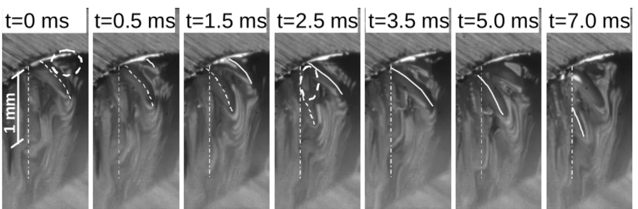
Recently high speed video filming technique has emerged as a powerful tool to investigate physical processes during laser material processing. In laser welding, for example, many interesting results concerning melt flow, spatter and plume ejection, hump formation, and so on, have been obtained [Fabbro 2005, Fabbro 2006, Weberpals 2010-1, Kawahito 2007, Schuster 2009, Eriksson 2011]. In laser cutting, however, it seems that the capability of the high speed video observation has not been exploited enough, probably because of difficulty to have a vision inside kerfs. Meanwhile, we can mention a recent study by Yudin et al. [Yudin 2007], who developed a technique to observe melt flow inside a kerf through a glass plate, which was attached onto a sample. Rose’s alloy [Yudin 2007] and mild steel [Grigory 2010] were cut in the experiments. It was confirmed that striations are developed by intermittent downward displacement of melt accumulations along kerf sides. However, precise observation of the top part of the kerf was not realised, so that it could not be revealed why the melt accumulations are generated from the top surface.
In view of these situations, this work aims to reveal the mechanism of striation generation during inert gas laser cutting of steel based on experimental observations of hydrodynamics of molten liquid on a kerf front using a high speed video camera. The outline of this thesis is briefly summarised as follows. In the next chapter 2, fundamental physical processes involved in laser cutting of steel are explained and discussed. The process of inert gas laser cutting of steel is composed of three fundamental processes: absorption of laser beam on kerf front, heat conduction and melting of the kerf front surface, and molten liquid ejection from the kerf by an assist-gas jet. These individual processes, however, have not been fully understood. In this study we re-examine several aspects. First, experimental investigation of the absorptivity is carried out. It is shown that the well-known Fresnel absorption law provides a good estimation of the absorptivity in laser cutting process. Then peculiarity of heat conduction process near the sample surface is discussed. We demonstrate that a kerf front profile near the top and bottom surfaces is deviated from the one which is obtained from a 1D approximation of the heat conduction equation. Finally it is revealed that the recoil pressure hardly contributes to melt ejection when the surface temperature is lower than the boiling temperature, as opposed to the
5
m
m
5
m
m
Figure 1-2 An example of striations left on kerf sides.
striation generation process.
In chapter 3, a review of theoretical studies on instability of melt flow and striation generation process is presented. Although we have not reached a conclusion on the mechanism of the striation generation, the review of the previous theoretical models becomes a basis for theoretical analyses performed in this work. Various models that have been proposed are categorised into three types: the models which only treat fluctuations of gas-liquid interface; those which only deal with fluctuations of solid-liquid interface; and those which consider both of them. Generally, the models analyse a response of the system when a small perturbation is added to a kerf front, and predict resonant oscillation of the system or transient transport of the perturbation. However, the problem is that the origin of this small perturbation is unknown. There are many hypotheses: unavoidable fluctuations of operating parameters of laser beam and assist-gas, strong interaction between melt film and assist-gas jet, peculiarity of heat conduction process near the sample surface, and surface tension of molten metal. To conclude on this mechanism, experimental investigations are being required.
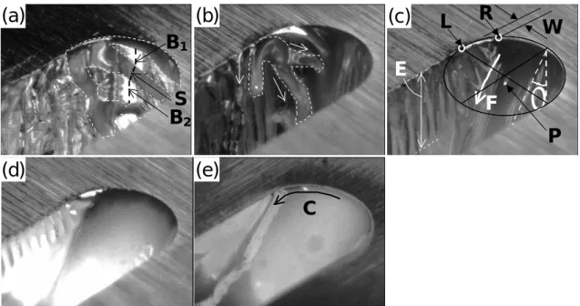
The chapter 4, the first main part of this study, is thus devoted to experimental observations of hydrodynamics of molten liquid on a kerf front with a high speed video camera. First, the hydrodynamics is visualised from the above of the sample, in order to clarify initiation of melt flow instabilities from the sample surface. The observation reveals unstable nature of the melt flow, which depends strongly on the cutting velocity. Molten droplets, so called humps and melt accumulations, are generated at the surface in the central and side parts of the kerf front, respectively, in low cutting velocity ranges. They are displaced downwards along the kerf front. It is clearly observed that striations are created as a result of this dynamics of melt accumulations on kerf sides. Also different characteristics are found between the instabilities in the centre and side parts of the kerf front, in terms of the frequency of the instability and the velocity range where the instability appears. A parametric study is also conducted in order to investigate dependence of the instability on various operating parameters. In the second configuration of the observation, melt film dynamics on a kerf front is visualised laterally through a glass plate. The result demonstrates that humps in the central part can also disturb the dynamics of the melt accumulations and influence quality of striations.
The origin of the melt flow instability and its relevance to striation generation process are discussed in the next chapter 5. We consider that the melt flow instabilities observed both in the central and side parts of the kerf front is caused by surface tension force which retains humps or melt accumulations at the surface while their size is small. A theoretical analysis of a force balance between the surface tension and the force induced by assist-gas jet predicts well the order of the pitch of the instabilities. The instability disappears for a high cutting velocity, since the surface tension can join two successive melt droplets along kerf front. An analysis shows scaling of instability by ; there exists a threshold angle above which the instability disappears. The different characteristics observed in the central and side parts can be explained by a geometrical effect. The instabilities observed in the two parts can thus be explained coherently by a single mechanism of the surface tension effect. We consider that striations are created by local melting of solid surface due to heat transfer from the melt accumulations on kerf sides. We estimate surface roughness from a theoretical analysis of the heat conduction process and the result shows reasonable agreement with experimental results. The results of lateral observations through a glass plate indicate that the stability of the central flow also affects striation generation process. As discussed above, the inclination angle of the front is a key parameter that controls this stability.
In chapter 6, we investigate the above-mentioned interesting problem of cut quality difference between CO2 and fibre/disc lasers, based on the mechanism of striation generation revealed in the previous
chapters. First, we compare laser cutting of stainless steel with a fibre and a CO2 lasers. It is revealed
that degradation of the cut surface quality for the 1 m wavelength occurs for a range of low less than 3 degrees. Then the mechanism of the laser wavelength dependence is discussed. We propose two mechanisms which can cause the wavelength dependence: stability of melt flow in the central part and dynamics of melt accumulations along kerf sides. The validity of each mechanism is confirmed by
analytical modelling of related physical processes. Both of the mechanisms are caused by the dependence of the absorption characteristics on laser wavelength. We finally propose that a possible way to improve cut quality for the 1 m wavelength is to use a laser beam with the radial polarisation, which offers better absorption on a kerf front for a low less than 3 degrees.
Chapter 2. Fundamental physical processes
RésuméLe processus de découpe laser avec un gaz inerte peut être présenté en trois étapes. D'abord, la puissance laser du faisceau incident est absorbée à la surface du matériau. Puis le transfert de chaleur dans le matériau et la fusion de la surface se produisent, enfin, le matériau fondu est éjecté de la saignée par le jet de gaz d’assistance. En fait, ces processus sont fortement couplés entre eux. Afin de modéliser le processus complet de découpe laser, plusieurs équations liées à chacun de ces processus doivent être résolues d’une façon auto-consistante. Malgré cette difficulté, un grand nombre de modèles ont été proposés, principalement en régime stationnaire, et certains ont permis de prévoir la capacité de découpe (l’épaisseur coupée ou la vitesse maximum de coupe pour des paramètres donnés). Cependant, le succès de ces modèles théoriques ne garantit pas la validité des différentes hypothèses faites dans chacun des processus physiques considérés. Par exemple, la capacité de découpe prévue n'est pas dépendante de la dynamique du métal fondu. De même, les processus non-stationnaires, tels que ceux décrivant la génération de stries, doivent dépendre de paramètres plus « fins » que ceux utilisés pour la description du régime stationnaire. Ainsi dans ce chapitre, les processus physiques présents au cours de ces trois étapes sont décrits en détail et plusieurs aspects sont réexaminés : On discutera la validité de la loi d'absorption de Fresnel, le détail du processus de conduction de chaleur près de la surface supérieure, et le rôle de la pression de recul dans le procédé d'éjection du métal fondu.
2.1 Processus d’absorption :
Le premier processus qui se produit dans la découpe laser est l'absorption du rayonnement laser sur un front avant de la saignée. Non seulement cette absorption peut être directe, mais des mécanismes secondaires tels que la diffusion du faisceau par des particules métalliques et/ou l’absorption du faisceau par un plasma induit peuvent se produire pendant la découpe laser. Ces effets secondaires seront négligés dans cette étude parce que la vaporisation est généralement très limitée dans les conditions optimales de découpe laser avec un gaz inerte.
Bien qu'un certain nombre d'études aient supposé une loi d'absorption de type « Fresnel » pour le processus d'absorption, peu d'expériences ont été effectuées pour vérifier la validité de cette loi. Ainsi dans cette étude, plusieurs expériences fondamentales ont été effectuées pour étudier la validité de cette loi (Annexe 1). Ces expériences montrent que cette loi devrait s'appliquer sur une gamme d'angles d'incidence élevée, ce qui est le cas de la découpe laser, et aussi qu’elle peut être utilisée pour une gamme de températures élevées, supérieures à la température de fusion Tm. L'absorptivité dans le
processus de découpe en conditions réelles a été estimée à partir de la mesure de la puissance transmise à travers la saignée et un accord raisonnable avec la loi théorique de Fresnel a été obtenu. Ainsi on peut conclure que la loi d'absorption de Fresnel est une bonne approximation pour évaluer l'absorptivité d'un faisceau laser sur le front avant de la saignée.
2.2 Processus de conduction :
Le processus suivant est le transfert de chaleur dans le matériau. Le matériau est chauffé puis fondu. Ceci détermine une puissance laser qui est nécessaire pour découper une épaisseur donnée et un profil approximatif du front avant de la saignée. Ces paramètres peuvent être évalués et sont basés sur un bilan de puissances. Par exemple l'angle d'inclinaison du front avant de la saignée peut être estimé à partir d'un bilan de puissances par unité d’épaisseur du matériau, composé de la puissance laser absorbée et de la puissance nécessaire pour fondre le matériau. La puissance absorbée par unité d’épaisseur augmente avec l’angle d’inclinaison . D'autre part, la puissance nécessaire à la fusion se compose d’une puissance nécessaire à la fusion de la partie centrale de la saignée et de la puissance perdue par conduction vers les parties latérales, à l’extérieur donc de la saignée. Cette somme augmente avec la vitesse de découpe Vc. Ainsi une augmentation de la vitesse Vc augmente , qui sera
l’un des paramètres les plus importants dans la discussion qui suit sur l'instabilité de l'écoulement de liquide.
L'analyse ci-dessus s'est concentrée sur la conduction de chaleur dans une section du matériau, située à l’intérieur de l’échantillon et dont la surface de la saignée est quasi-parallèle à l'axe du faisceau laser. Cette approximation ne peut pas être valide dans les régions situées près de la surface supérieure, où le flux thermique, dans une direction verticale, est alors modifié. Cet aspect est étudié pour la première fois, et il est nécessaire de le faire, car il peut être lié à l'initiation de stries à partir de la surface supérieure. La modification du profil du front avant de la saignée issue de la considération de ce flux thermique vertical a été analysée pour une distribution « top-hat » de la tâche focale de faisceau laser. On montre alors que le profil de la saignée au niveau de la surface supérieure ne peut pas être droit comme habituellement considéré lors d’une approximation 1D, mais doit s’arrondir au niveau de la jonction du front avant et de la face supérieure.
2.3 Hydrodynamique du liquide éjecté :
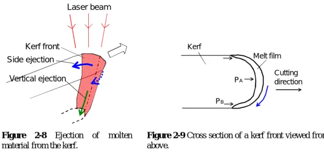
Enfin, le processus qui intervient après le transfert de chaleur et la fusion, est l’éjection du matériau fondu de la saignée par un jet de gaz intense, généralement coaxial au faisceau laser. Dans les études théoriques issues de la bibliographie, deux principaux mécanismes ont été considérés dans ce processus d'éjection du liquide métallique: l’éjection verticale liée au gaz d’assistance et l'éjection latérale résultant de la pression de recul générée par le laser. Cependant, notre étude expérimentale sur la pression de recul (Annexe 2) a clairement démontré pour la première fois que l'éjection latérale par la pression de recul pouvait être négligée tant que la température de surface de la couche liquide est inférieure à la température d'ébullition du matériau. Ce résultat nous permet alors de nous concentrer uniquement sur l'éjection par le gaz d’assistance dans les discussions suivantes, ce qui simplifiera considérablement les analyses.
Dans une condition typique de découpe laser d’acier avec un gaz inerte, la pression du gaz d’assistance est au moins de l’ordre de 10 bar. Ceci induit une distribution du champ de vitesses dans ce gaz issu de la buse très complexe, en partie en raison de la présence d’ondes de choc. Les caractéristiques de cet écoulement complexe ont déjà été étudiées expérimentalement et numériquement et on peut considérer que les caractéristiques de cet écoulement sont plutôt bien connues. L'écoulement supersonique du gaz étant assez sensible aux paramètres opératoires, nous avons par conséquent choisi d’utiliser un jet de gaz en régime subsonique pour la suite de cette étude.
Il y a deux mécanismes entraînant l'éjection du métal fondu par le gaz d’assistance, qui sont discutés: le gradient de pression du gaz et la contrainte de cisaillement. La dynamique d'éjection du liquide peut être obtenue par la résolution des équations de Navier-Stokes. Ce qui est relativement difficile, du fait de la présence d’une surface libre de l'interface gaz-liquide et également d’un champ de vitesse du gaz assez complexe, comme mentionné précédemment. Jusqu'à présent, ces modèles théoriques ont été limités au cas 2D et supposent un gradient de pression constant, ou une contrainte de cisaillement constante avec généralement un nombre de Reynolds faible. Si on admet une contrainte de cisaillement constante issue de l’écoulement, la vitesse de la couche liquide est être donnée par (m/2l) (: la contrainte de cisaillement, m: l’épaisseur de la couche liquide, l: la viscosité du
liquide).
On discute également plusieurs modèles théoriques qui prennent en considération l’ensemble des processus rappelés ci-dessus: l’absorption d’un faisceau laser sur le front avant de la saignée inclinée, la conduction de chaleur, l'hydrodynamique du métal fondu sur le front avant. Ces modèles, indépendamment de leur dimension 2D ou 3D, visent à obtenir un profil du front avant de la saignée dans l'état stationnaire pour un ensemble donné des paramètres opératoires. Le profil obtenu doit satisfaire toutes les équations différentielles représentatives des différents phénomènes physiques, qui doivent être résolues d’une façon consistante. Ces modèles semi-analytiques permettent généralement de prévoir les profondeurs coupées maximum ou les vitesses maximum de coupe observées expérimentalement. Ils ne sont cependant pas capables de prévoir et ni de quantifier l’état des stries, puisqu'ils supposent un état stationnaire, la génération de stries étant un processus essentiellement instationnaire.
Introduction
The process of inert gas laser cutting of steel in a quasi-stationary regime can be divided into three processes, as schematically designated using bold arrows in figure 2-1: (i) power of the laser beam is absorbed on the kerf front; (ii) heat transfer occurs and the kerf front surface is melted; (iii) the produced melt film is blown off from the kerf by an assist-gas jet. Actually these processes are coupled to each other. In order to model the entire laser cutting process, several sets of differential equations related to each process have to be solved self-consistently. In spite of this difficulty, a number of models have been proposed as steady state laser cutting models, which have succeeded to predict cutting capacity (i.e. maximum cutting thickness or maximum cutting speed for a given laser condition).
In spite of this success, it seems that different assumptions made in modelling have to be re-examined. One reason is that the success of the theoretical models does not guarantee the validity of different assumptions made in each of the physical processes. For example, as mentioned in the following, the predicted cutting capacity is not influenced strongly by a way of modelling of melt film dynamics. It should also be pointed out that time-dependent phenomena such as striation generation process, which is the topic of this thesis, should be more sensitive to model assumptions than the characteristics under stationary condition.
Therefore, in this chapter, physics of the above three processes is described and several aspects are reinvestigated. Among these are: the validity of Fresnel absorption law, peculiarity of heat conduction process near sample surface, and the role of recoil pressure in melt ejection process. It is shown from experimental measurements of absorptivity that the Fresnel law can be applied to laser cutting, where the incidence angle of laser beam is quite large and the surface temperature of the absorbing kerf surface is kept high over the melting temperature. As regards heat conduction process, it is pointed out that two dimensional approximation of heat conduction process on a plane perpendicular the laser beam axis, which has been often used in the previous studies, is not appropriate in the regions near the top and bottom surfaces. Discrepancy of the kerf front profile from this approximation is discussed. Finally, we conclude from a result of an experimental investigation of recoil pressure that lateral ejection of melt film from the central part of kerf front to kerf side regions can be neglected when the surface temperature of kerf front is below the boiling temperature.
2.1 Absorption
Laser cutting process begins with absorption of laser beam and heating material on the kerf front. The incoming laser beam is not absorbed by 100%, but is partially reflected. According to the Fresnel absorption theory of electric magnetic waves at an interface of two different materials (air and steel are considered here.), the absorptivity A primarily depends on the refractive index n and the extinction coefficient k [Dausinger 1993]:
Absorption of laser beam on kerf front
Heat transfer and melting of the kerf front
Dynamics of melt film under force of gas Kerf profile,
Melt film properties Absorption of laser beam on kerf front
Heat transfer and melting of the kerf front
Dynamics of melt film under force of gas Kerf profile,
Melt film properties
2
s pA
A
A
(2-1),
sin
2
sin
1
sin
4
2 2 2
n
k
n
n
A
p (2-2),
2 2 2 sin sin 2 sin 4 n k n n As (2-3). Here Ap and As are the absorptivities for the p-polarisation and the s-polarisation, respectively. Theabsorptivity A in eq.(2-1) assumes the random polarisation of the incoming laser beam. As is clear from eqs.(2-1) to (2-3), the absorptivity A depends on n and k, which are determined by the laser wavelength and the surface temperature of kerf front surface, and also on the local inclination angle of the kerf front. Please refer to figure 2-3 for the definition of . Please note that is different from the incidence angle that is defined as the angle between the incident direction of the laser beam and
the normal of kerf front surface. As can be seen in figure 2-2, angular dependence of absorptivity of steel is different for laser wavelengths of 1 μm and 10 μm.
The above Fresnel formula has widely been used in the previous papers on laser cutting [Mahrle 2009, Powell 2011]. However, there remains room for doubt to apply the expression directly to the cutting process, where the absorbing surface has high temperature. It should be noted that the Fresnel absorption law is applicable for ideally smooth surface at room temperature. According to the previous experiments in our laboratory, the absorptivity measured for 1 m was as high as 80% for drilling [Schneider 2006], and 60% for welding [Fabbro 2005], while the absorptivity for 1 μm is predicted to be below 50% as shown in figure 2-2. For cutting with a CO2 laser, the measured absorptivity was
60-70% in the case of oxygen laser cutting [Miyamoto 1991], and another experiment conducted in our laboratory suggests that the absorptivity is around 50% for stainless steel cutting by a CO2 laser
with nitrogen gas [Mas 2003-1].
To verify the applicability of the Fresnel absorption formula to laser cutting process, two types of experiments were conducted. The object of the first experiment was to confirm the angular dependence of the absorptivity, especially for low , which is usually encountered in laser cutting. The details are explained in the Annex 1. Angular dependence of the absorptivity for a disc laser beam (Laser wavelength: 1.03 m) was measured for a sheet of pure iron. The sample was placed above an integrating sphere and the reflected light was collected in the integrating sphere. The measurement was carried out for the two polarisations s and p. The surface temperature of the sample must have been
0 0.1 0.2 0.3 0.4 0.5 0 10 20 30 40 50 60 70 80 90 (degrees) A ( ) 10.6 m m 1.06 m m 0 0.1 0.2 0.3 0.4 0.5 0 2 4 6 (degrees) A ( ) 10.6 m m 1.06 m m
pulse irradiation. The results show reasonable agreement with the theoretical predictions of eqs.(2-2) and (2-3). The absorptivity for both the p and s polarisations exhibit increase with the increase of , and the absorptivity was much higher for the p-polarisation than for the s-polarisation. The present result agrees with a previous work [Touvrey 2006], where the increase of absorptivity was confirmed with the increase of for Tantalum.
The second experiment was conducted to investigate influence of temperature dependence of the absorptivity. The details of this experiment are explained in the Annex 2. A sample of pure iron was placed under an integrating sphere, which collected the reflected light from the sample surface. The incidence angle of the laser beam was about 5 degrees ( = 85 degrees). Time evolution of the
absorptivity was measured during a single pulse irradiation by a disc laser beam. In another experiment with the same laser irradiation condition, the surface temperature of the irradiated spot was measured as a function of time by pyrometry using a high speed video camera. Combining these two results, the temperature dependence of the absorptivity could be estimated. The result shows that the absorptivity for pure iron is almost constant up to the boiling point Tv. The previous studies have
shown that the absorptivity of steel for the 1 m wavelength does not change so much up to 1400 °C [Dausinger 1993], and up to 2650 K [Kraus 1986]. The result in this work demonstrated for the first time that this extrapolation is valid up to Tv.
The results of the above two experiments support the validity of the theoretical Fresnel absorption law for laser cutting with a 1 m laser beam. That is, it is reasonable to extend the absorption law to a region of low using the values n and k that are obtained by an experiment with a high near 90 degrees. Also, the influence of the temperature change is negligibly small.
Next the absorptivity in real cutting process was measured experimentally to confirm that the absorptivity can certainly be estimated from the Fresnel absorption law. To obtain the absorptivity during the cutting process, we measured power transmitted through a kerf (Figure 2-3). The details of this measurement are described in Annex 1. The transmitted power is composed of two components: the power reflected on the kerf front and transmitted downwards, and the power directly transmitted without any interaction with the kerf front. The measurement of the surface area of the kerf front intercepting the laser beam allowed us to distinguish the two components and as a result to estimate the absorptivity on the kerf front. The measured absorptivity was around 60%. The value is slightly higher than the value predicted from the Fresnel absorption law. But it seems reasonable to conclude that the Fresnel law approximately describes the absorption during laser cutting of steel.
In conclusion, the experimental results obtained in this study show reasonable agreement with the Fresnel absorption formula. Thus the Fresnel law will be assumed in the following discussion.
Then a question arises. Why was the absorptivity as high as 80 % obtained in laser drilling of steel [Schneider 2006]? It is likely that multi-reflection effect could have caused an apparent increase of the absorptivity. In this experiment, the reflectivity was measured at about 0.1 ms after the initiation of laser pulse. This was because 0.1 ms was needed for a complete rise up of the laser power. The depth of the hole at 0.1 ms can be estimated from an integral of drilling velocity over 0.1 ms. At a peak power of 5 kW, for example, the drilling velocity Vd in the equilibrium state was measured to be 2.5
m/s. Considering the fact that the characteristic time to reach the equilibrium regime (~ /Vd 2 ) is much
P
TLaser
beam
V
cα
P
inP
T =(1-A(α))P
in+P
transP
trans
P
TLaser
beam
V
cα
P
inP
T =(1-A(α))P
in+P
transP
trans
smaller than the characteristic time of the rise up of the laser power (0.1 ms), one can assume that the instantaneous drilling velocity is determined by the beam intensity at the same time. If we approximate the rise up of the power to 5 kW is linear and the drilling velocity is proportional to the beam intensity, the depth at 0.1 ms is estimated to be (1/2) x (0.1 ms) x (2.5 m/s) ≈ 125 m. This is not negligible compared with the beam diameter of 330 m. One can thus expect that multi-reflection could have increased the effective absorptivity.
Up to now direct absorption of laser beam has only been discussed. Let us mention here other heat transfer mechanisms: scattering of the laser beam and the inverse bremsstrahlung. When the scattering or the inverse bremsstrahlung occurs, the kerf front would be heated from the secondary heat source in any case, in a more homogenised manner than the direct absorption of the laser beam. These secondary absorption processes might be important for a discussion on the difference of cut surface quality between fibre/disc and CO2 lasers. In this study, however, they are neglected for the following
reasons.
The scattering effect is more important for a 1 m laser beam than a 10 m CO2 laser beam, since the
scattering intensity increases with a decrease of the laser wavelength L [Hansen 1994, Lacroix 1998,
Greses 2004]. Scattering effects such as power attenuation and diffusive scattering were confirmed in experiments with 1 m YAG laser beams [Matsunawa 1985, Greses 2004] for welding regime where no assist gas jet was applied. In conventional laser cutting with assist gas, however, density of metallic particles above a kerf front is expected to be too small to cause appreciable scattering, because of a lower temperature (Ts < Tv) and a stream of the assist-gas jet which blows out the particles.
The attenuation coefficient for the inverse bremsstrahlung increases with L2. It can be negligible for
a 1 m laser beam [Lacroix 1997, Mahrle 2006] but may have to be accounted for a 10 m CO2 laser
beam. A previous study of laser cutting of thin sheets with a continuous wave CO2 laser shows that
extremely high power density in the order of 100 MW/cm2 involves plasma formation during laser cutting process [Petring 1991]. In this regime, dependence of cutting velocity on the laser beam polarisation disappears. This suggests that the Fresnel absorption formula is not valid anymore. A possible explanation is the depolarisation of the laser beam by laser-induced plasma. It is also possible that heat transfer from the laser-induced plasma is dominant over the direct absorption from the laser beam.
In a lower intensity range, however, plasma formation is considered to be negligible. To see this point, let us refer to a recent experimental measurement of temperature on kerf front surface [Onuseit 2011]. In this experiment, the surface temperature was determined from emission spectrum from the surface, which was supposed to be a grey body. It was found that any emission line of neutral Fe atoms was not observed for a temperature range Ts < Tv. This suggests that plasma was not formed in this
temperature range. Of course, Ts can reach Tv and plasma may be ignited. However, the above study
also showed that excess of the temperature over Tv was observed only around the bottom part of a 2
mm thick sample and for a cutting speed near the process limit [Onuseit 2011]. It was confirmed also that when Ts > Tv, the quality of cut surfaces became worse. Horisawa et al. [Horisawa 2000] reported
a similar result from cutting experiments of 3 mm mild steel sheet. Bright blue plasma originating from N2 and N2
+
was observed when the cutting speed was set too high. It was reported that an explosive evaporation of molten material was observed almost simultaneously with the plasma formation and the molten material was scattered diffusively, independently of direction of assist-gas jet. The plasma formation was correlated with a bad quality of the kerf surface.
The above experimental results indicate that the plasma formation generally degrades the cut surface quality in laser cutting and suggest that it can be negligible for laser cutting with moderate laser beam intensity at least for an optimal cut velocity range where best cut surface quality can be obtained. Considering an experimental fact that the difference fibre/disc and CO2 lasers for thick section cutting
can be identified in a wide velocity range, we can conclude that the plasma effect should not be the main mechanism for the quality difference.
2.2 Heat conduction
2.2.1 Global energy balance
Let us consider first the dependence of the inclination angle of the kerf front on the cutting velocity Vc. This
can be considered from the equation of power balance per unit length along kerf depth, which is written as
l m s
a p p p
p (2-4) All the terms have the dimension of W/m. The term pa in the left side is the energy input to the system per unit depth. It can be approximated using the incident laser intensity IL, the absorptivity A, the radius rk of the kerf front (rk ≈ df /2) and the mean tilting angle :
)
2
tan
(
L ka
A
I
r
p
(2-5) We have taken (2rk) as the characteristic length of thepart along the kerf front which receives laser beam,
neglecting its dependence on depth from the surface. The first and second terms on the right hand side of (2-4) represent the powers necessary to melt the solid material in the axial region in front of the kerf front (see figure 2-4)and to heat it further to Tl, which is the mean temperature of liquid:
k
ps
m
m
s s V r C T T L p
2 0 (2-6)
k
pl
l m
l m V r C T T p
2 (2-7) Here T0 is the initial temperature, Tm is the melting temperature, and Lm is the latent heat, and s (l),and Cps (Cpl) are the density and heat capacity of solid (liquid), respectively. The third term in the right
hand side of eq.(2-4) is the power lost by heat conduction into the solid parts outside of the axial region, which can be expressed as [Schulz 1993]
3 . 0 0 2 4 K T T Pe pl m (2-8) Here K is the thermal conductivity of the material. And
c
kV
r
Pe (2-9) is the non-dimensional Péclet number. From eqs.(2-4)-(2-9), one obtains
3 . 0 0 0 2 4 2 tan 2 ) ( C T T L C T T Pe K T T Pe r I A
L k
s ps m
s m
l pl l m m (2-10)The right hand side is a monotonous increasing function of Pe, which is proportional to Vc. Thus the
expression shows that for a given conditions of IL and rk, the angle increases monotonously with the
increase of Vc.
2.2.2 Analysis of kerf front profile
For a top-hat intensity distribution, eq.(2-10) predicts a straight kerf front with a constant inclination angle all along the front. However, a kerf front profile near the top and bottom surfaces is deviated from the straight line. The analysis limited on a 2D plane as in figure 2-4 is not valid in the top and bottom regions, since heat flux in the direction of the thickness of the sample has to be taken into account. Let us analyse this modification of the kerf front profile from the straight line.
Figure 2-5 shows the 2D model considered in the following. The plane shown in the figure corresponds to the central symmetric plane of the kerf. Laser beam has top-hat intensity distribution with the constant intensity of IL (W/m2). The laboratory frame where laser beam is fixed is adopted.
The material, which flows from the left with constant velocity Vc (m/s), is heated as it approaches the
kerf front (surface “3”). It is assumed that the material disappears as soon as the temperature of the material reaches Tm and it absorbs the latent heat. This means that the melt layer is neglected in the
analysis. This simplification should be justified when the thickness of the melt layer is kept small Axial region
V
c2r
kI
LKerf
owing to rapid ejection assisted by a strong gas jet. Another assumption is the 100 % absorption of the laser beam without any reflection on the kerf front. 2.2.3 Formulation of the problem
Time dependent two dimensional heat transfer process is considered. Taking into account the convection term due to the displacement of material with the cutting speed of Vc, the heat conduction
equation is expressed as 2 2 2 2 z T x T x T V t T c
(2-11). Here pC
K
is the thermal diffusion coefficient (ρ: density, Cp:
heat capacity, and K: thermal conductivity). Temperature dependence of these parameters is neglected in order to make analytical investigation easier and to see more clearly the dependence of the characteristic of the profile on operating conditions.
As already mentioned, only the solid part is taken into account; a part of the material is assumed to disappear instantaneously as soon as its temperature reaches Tm and it absorbs the latent heat for
melting. In this case, the boundary condition on the surface 3 of the inclined kerf front (see figure 2-5) is given by
m
T
T
on surface 3 (2-12). Another boundary condition on the surface 3 concerns the continuity of the heat flux:)
(
z L x c m z xL
V
n
I
n
z
T
n
x
T
n
K
on surface 3 (2-13).The second term in the left hand side represents the heat flux consumed for latent heat during the removal process. The boundary condition on the surface 2 is expressed as
L I z T K
x
x
0 on surface 2 (2-14), 0 x
x
0considering the top-hat intensity distribution. The surface 1 serves as inlet and the temperature can be defined as
0
T
T
on surface 1 (2-15), where T0 is the room temperature.In the following we look for a stationary solution of the kerf front profile which satisfies eqs.(2-11)-(2-15) for a given set of Vc and I0.
2.2.4 1D approximation
Before going into detailed analysis of the problem, it is worthwhile to mention one-dimensional approximation of the problem to grasp a rough profile of the kerf front. Let us consider the case in figure 2-6(a) where the laser beam is irradiated only on the kerf front (x = x0 in figure 2-5). We
consider the energy balance in the sliced part in figure 2-6(a), which is in deep part (large z) where heat exchange with top surface region is neglected. One can estimate the inclination angle of the kerf front from the following energy balance equation expressed per unit thickness.
C T T L
V I tan
(2-16).x
v
T
=
T
mI
Lx= x
0n
n
xn
zIns ulated (y= -
8
)
1
2
3
4
T
=
T
0=
0
(
x=
-)
8
v
z
x
v
T
=
T
mI
Lx= x
0n
n
n
xn
zIns ulated (y= -
8
)
Ins ulated (y= -
8
)
1
2
3
4
T
=
T
0=
0
(
x=
-)
8
T
=
T
0=
0
(
x=
-)
8
v
z
C zAn important outcome of eq.(2-16) is that the angle increases with the cutting velocity Vc and
decreases with the laser intensity IL.
This non-dimensional parameter tanα is important, since it is the parameter that governs the characteristic of the solution. If we also introduce other non-dimensional parameters for time and space,
cV
x
,
cV
z
2'
cV
t
t
(2-17).
0
0'
T
T
T
T
T
m
m m pL
T
T
C
St
0then eqs.(2-11) to (2-15) are rewritten as follows.
2 2 2 2
'
'
'
'
'
T
T
T
t
T
(2-11’). 1 ' T on surface 3 (2-12’).
tan
1
'
'
1 1
n
St
St
n
T
n
T
n
on surface 3 (2-13’).
tan 1 ' 1 T Stx
x
0 on surface 2 (2-14’). 0 x
x
0 0 ' T on surface 1 (2-15’),which are no more dependent on Vc nor I0. This means that, if the non-dimensional parameter tanαis
the same, the characteristic of the solution of eqs.(2-11)-(2-15) stays the same, except that there will be some modification in scale factors of space and time given by (2-17). Thus in the following we investigate the dependence of the profile on this parameter.
It can be noted here that the inclination angle α of the front certainly plays a significant role in real physical processes. For example, Fabbro proposed that α is a crucial parameter, which determines the degree of interaction between gas vapour jet emitted from a keyhole front and the back melt surface of the keyhole during laser welding [Fabbro 2010]. As an example of such interaction, Weberpals et al. showed that ejection angle of spatters from a keyhole is correlated with α [Weberpals 2008].
2.2.5 Temperature drop near surface
The simple straight line profile in figure 2-6 of the 1D approximation cannot be the solution of (2-11)-(2-15), because the temperature distribution on the surface 3 cannot be kept constant at Tm due
to heat flux in the direction of the thickness of the sample. Real temperature distribution suffers from a slight drop around the corner A. We analyse in the following this modification of the temperature field in this region.