This is an author-deposited version published in: https://sam.ensam.eu Handle ID: .http://hdl.handle.net/10985/13423
To cite this version :
Jinlin GONG, Hussein ZAHR, Eric SEMAIL, Mohamed TRABELSI, Bassel ASLAN, Franck SCUILLER - Design Considerations of Five-Phase Machine with Double p/3p Polarity - IEEE Transactions on Energy Conversion p.1-13 - 2018
Abstract—In the context of traction drives with required
torque transient capabilities and a classically wide flux weakening speed range, this paper gives design considerations of a particular Double-Polarity (DP) five-phase machine. Beyond its intrinsic fault tolerance due its five phases, its specificity is the ability to develop torques of comparable values under three kinds of supply: with only first, third or both first and third sinusoidal currents. This property, due to first (E1) and third (E3) harmonic electromotive forces (emf) of comparable values, gives more degrees of freedom for the control of the machine. Unlike three-phase sinusoidal machine, flux weakening is no more the unique solution when maximum voltage is reached. Thanks to the extra degrees of freedom in this kind of machines, more possibilities for the control of the torque and current supply can be applied. At first, elements for the choice of slots/poles combination of such DP machines are given. Then, in case of an Interior Permanent Magnet Synchronous Machine (IPMSM), possible adaptations of the rotor are proposed in order to bring the double p/3p polarity property. The last design criterion considered is the level of eddy-current losses, important at high frequencies. For proof of the concept effectiveness, a prototype with a five-phase fractional-slot concentrated winding of 40 slots and 16/48 poles is presented with results from experimental set-up and Finite Element modeling. A comparison with equivalent no-fault-tolerant three-phase 24 slots /16 poles machines is also carried out.
Index Terms—double polarity, five-phase machine, flux
weakening, interior permanent magnet synchronous machine
NOMENCLATURE
DP Double Polarity, rotor with p and 3p poles
P Pole pair number
RMS Root Mean Square
MM Main Machine (associated to the first (d1, q1)
subspace and to the first harmonic).
SM Secondary Machine (associated to the
secondary (d3, q3) subspace and to the third harmonic).
Φ1, Φ3 MM and SM peak amplitude of sinusoidal flux
Manuscript received Mars 20, 2017; revised February 14, 2018; accepted June 10, 2018. Paper no. TEC.00210-2017.
J. Gong is with School of Electrical Engineering of Shandong University, Jinan 250061, China (e-mail: [email protected]).
H. Zahr, E. Semail, M. Trablesi and B. Aslan are with the Laboratory of Electrical Engineering and Power Electronics of Lille (L2EP), Atrs et Métiers ParisTech, Lille 59034, France (e-mail: hussein.zahr; eric.semail; mohamed.trablesi; [email protected]).
F. Scuiller is with the Naval Academy Research Institute, Brest 29240, France (e-mail: [email protected]).
Φm1, Φm3 MM and SM peak amplitude of sinusoidal flux
due to magnet.
L1, L3 MM and SM cyclic inductances.
θ1, θ3 MM and SM back EMF to current angles.
I1 , I3 MM and SM peak amplitude of sinusoidal
currents.
E1 , E3 MM and SM peak amplitude of sinusoidal
electromotive forces.
(ξw)1, (ξw)3 Winding factor for the first and third harmonics I. INTRODUCTION
nduction and excited synchronous multiphase machines have been widely used in critical applications, such as marine applications, where fault tolerant capability is required [1], [2]. Even if a number of phases higher than three can decrease the reliability because of a higher probability of fault occurrence due to higher numbers of components and connections, on contrary the fault-tolerance to a fault of the Power Converter leading to opened phase, is higher: three is effectively the minimum number of phases which allows to produce the required rotating field for a machine [3]. For a three-phase machine, the loss of one phase prevents to generate the field. Another reason of multiphase machines in low voltage and/or high power applications, is that a high number of phases also allows a power splitting with lower current per phase and consequently per power component. But one main particular physical property of multiphase machines is their ability to benefit, thanks to vector control, from high torque quality while being supplied with non-sinusoidal currents. It is then possible with Permanent Magnet (PM) multiphase machines with high number of phases to obtain the same high torque density of three-phase DC-brushless machines, with trapezoidal emf and currents, but without torque pulsations [4], [5]. Thus, the maximum potential gain is 41.4% [4] in comparison with machines with a sinusoidal emf supplied by a sinusoidal current with the same RMS current and peak emf amplitude.
For induction machines, it has been shown that, for a given RMS current, it is possible to increase the torque density by imposing non-sinusoidal air gap magnetic flux density and corresponding harmonic currents. With eleven-phase induction machines, [6] obtains a 14% improvement of torque with a third harmonic injection and up to 27% with an injection of harmonics up to the 9th harmonic. In [7] the maximum torque at any speed, even in the flux-weakening region, is optimally found by injecting higher-order harmonics of magnetic field in a machine with classical integer-slot windings: the improvement of the overload torque can be up to 17% for a
Design Considerations of Five-Phase Machine
with Double p/3p Polarity
J. Gong, H. Zahr, E. Semail, M. Trabelsi, B. Aslan, F. Scuiller
given RMS current. With more than eleven phases, industrial applications [2] requiring fault-tolerance, high torque density and quality already exist: military surface-ship with a 15-phase 19 MW induction machine and submarines from 2 to 5 MW with multiphase Surface Permanent Magnet Synchronous Machines (SPMSM).
With five-phase machines, which are more attractive for lower power applications because they require five legs only, the increase of torque density is more challenging and not so easy to obtain in steady-state operation because only the first and the third harmonics can be used while keeping the constraint of vector control for high torque quality. It is more when working in transient operations, keeping a maximum peak current, that improvements have been obtained. In [8], with a 30-slot/8-pole/5-phase SPMSM, a 20% improvement in torque density can be obtained with both the first and the third current supply while keeping the same peak current as for sinus control. In [9], a 10-slot/8-pole SPMSM with a PM shaping technique in accordance with harmonic current injection ratio is investigated. Compared with a Sine shape rotor and Sine current wave form, a Sine +3rd PM shape rotor and current waveform with 3rd optimal current can lead to an increase of 30% of the torque density, with respect to the same peak current and maximum magnet thickness. In these two papers [8], [9], the (ξw)3 winding factor for the third harmonic is weak (less than 0.6) with as a consequence an expected low impact of the third harmonic current injection in case of imposed RMS current. On the contrary, papers [10], [11], which present a significant increase of torque density with SPMSM (respectively 15% and 17 %), consider machines whose (ξw)3 is higher than 0.85.
As considered in [12] for the inverters supplying multiphase machines, the background idea of this paper is to propose for the design of an innovative exploitation of additional degrees of freedom of multiphase machines in comparison with three-phase ones. Of course, intrinsic fault tolerance and capability of higher power splitting of multiphase machines are kept.
In [13], [14], the exploitation of the degrees of freedom is done by choosing a combination of different kinds of winding connections in order to optimize the fault tolerant capability thanks to the cancellation of the third harmonic flux component. In the present paper, the aim is to design machines whose torque can be developed, with equal share, by each first and third harmonic of current and emf. In this case, a real degree of freedom for the control will emerge. Considering the three-phase traction machines, the flux-weakening is almost appearing as the unique solution to increase the speed above the base speed when the maximum voltage imposed by the voltage source inverter is reached. When in flux weakening the machine is not with sinusoidal characteristics anymore, the distortion of voltage can induce severe constraints on the voltage supply as described in [15]. In order to reduce this constraint, the paper proposes to explore a new family of machine whose torque can be produced by two harmonics of current thanks to two corresponding harmonics of emf. In [16], this concept of DP machine was presented and numerically
validated for low-voltage automotive application: the torque/speed characteristic was the merging of two torque/speed characteristics obtained for the two polarities allowed for a five-phase machine with a special 8-pole/24-pole rotor. In [17], Finite Element (FE) simulation shows how, the torque/speed characteristics can be largely extended in constant power area for transient operations in such a machine. In [18], for the same kind of low-voltage automotive field, a similar concept which consists in changing the number of pole-pairs is presented for a 60-phase induction machine. In this case the polarity is induced in the rotor by the choice of the polarity of the magneto-motive force (mmf). With such a high number of phases, the number of freedom degrees is high and the use of three different polarities from p=1 to p=3 is proposed in [19]. Thus, as a gearbox for a thermal engine, a wide extension of constant power range for an induction machine is enabled. In [20], a more general study has been achieved for such DP machine in case of SPMSM with low armature reaction showing potentialities of such machines.
In this paper, as in [21], a multiphase concentrated windings IPMSM has been chosen in order to fulfill the main features of a traction machine for automotive:
High transient torque and power during, for example, accelerations and regenerative braking;
Wide speed range at constant power in order to optimize the sizing of the power converter;
Low losses associated with eddy currents when high frequencies are required at medium/high speeds; Compactness by use of magnets, numerous poles and
concentrated windings.
The paper is organized as follows. In section II general design considerations including the average torque calculation, the choice of slot/pole combination, and the rotor structure are presented for such DP five-phase IPMSM. Section III develops considerations on eddy currents which impact the choice of machine structures intended to work in large speed area at constant power. In sections IV and V, the main features of a prototype with 40 slots and 16/48 poles are given: the concept of shared high quality torque production with two polarities is validated numerically and experimentally. In the last section, in order to highlight the potentialities of the bi-harmonic machines especially for transient operations, a comparison with the Torque/Speed characteristics of a no-fault tolerant three-phase machine whose characteristics fulfill the same main features previously given for a traction machine is presented.
II. ELEMENTS FOR OPTIMAL DESIGN OF 5-PHASE
DOUBLE-POLARITY (DP)MACHINE
This section aims to present design considerations for a DP five-phase PM machine for traction, as in [22], [23], with capability for developing high torque during transient operation, good efficiency at steady state. Moreover, for the request of compactness and easy manufacturing as it is the case for traction applications, concentrated tooth windings with a high number of poles have been at first chosen, leading to high
frequencies [24] at high speeds. In order to protect the magnets from eddy currents, a rotor with interior magnets is considered with low expected PM losses [25], [26]. To limit the iron losses, harmonics of mmf must be carefully chosen. An adequate Maximum Torque Per Losses (MTPL) strategy which takes into account eddy current losses can be used, as in [17], [27], [28], at high frequencies when the maximum voltage is reached. Under the base speed, the maximum voltage is not reached. In this case, a classical Maximum Torque Per Ampere (MTPA) strategy is used, leading as usual to a vector current in phase with the vector emf when reluctance effects are neglected.
The following elements of design will be presented: Dependence of the average torque with the first and third
harmonics for a low speed region under MTPA strategy; Proposal of an adequate choice of windings taking into account torque density for the low speed region and iron losses for high speed region;
Proposal of an adequate rotor structure for DP effect.
A. Average torque calculation for five-phase PM machines
Using a co-energy approach and neglecting the reluctance effect, it is possible to express the torque as a sum of two torques produced in the two characteristic rotating frames (d1,
q1), (d3, q3) associated with the first and third harmonics:
1 1 1 3 3 3 2 1 1 3 3 5 cos 3 cos 2 5 2 cos 3 1 cos 2 em m m m RMS m RMS T p I I p rI r I (1) with
2
/2 3 2 1 I I IRMS and 2 2 1/ 1 3 rI I IThe classical MTPA control strategy which makes it possible to obtain the Maximum Torque per RMS current is considered. For a given RMS value of applied current IRMS, the
optimal distribution (r) between the first and the third harmonic current can be deduced by solving the equation dT/dr=0. The results of optimization are:
θ1opt= θ3opt=0 (MTPA)
(2) 1 1 3 3 1 2 2 1 1 3 3 3 2 1 1 3 m m opt RMS m m E E I r I E E
The final maximum torque for a given RMS current is expressed in (3). Therefore, the improvement of torque Gopt
thanks to optimal current harmonics exploration is defined as in (4).
2 2 1 3 max 5 2 9 2 em RMS m m T p I (3)
2 max 3 1 1 3 max 3 1 2 , 0 em m opt m em RMS T G T I I I (4)From (3) and (4), we can conclude that the optimal improvement of torque by injecting the third harmonic current
depends on the ratio of PM flux Φm3/Φm1. The larger the ratio is,
the larger the gain of torque can be obtained. Considering only one spatial harmonic of flux p∙h (h=1 or 3) in the air gap, the PM flux linked by one phase is given in (5).
/ 0 ( ) ( ) sin( ) p h h w h l Nph Brotor h h p Rrotor d (5) (5) is simplified in (6).
w h rotor
h h B G p h and G = 2Nph∙Rrotor∙l (6)Where l is the rotor length; (Brotor)h is the maximal value of
spatial harmonic p∙h in the airgap generated by PMs; Nph is the
number of turns per phase; Rrotor is the radius of the rotor.
Substituting (6) into (4), the optimal gain of the torque can be calculated,
2 2 3 3 3 1 1 1 3 1 m 1 w rotor opt m w rotor B G B (7)With (7) the designer is provided a formula which shows how the ratio between the maximum torque and the one obtained only by the first harmonic can be modified in a machine supplied by two harmonics of currents. Gopt must be
considered as an index which allows to evaluate, for a given rotor structure, the impact of the windings and vice-versa for a given winding, the impact of the rotor structure.
Clearly, two design parameters coexist: the ratio of harmonic winding factors (ξw)3/(ξw)1 andthe ratio of air gap flux densities due to the rotor (Brotor)3/(Brotor)1. The former concerns the winding configurations of machines i.e. the slot/pole combination and the type of winding. The latter is related to the magnetic properties of PMs and the rotor topology.
In the following parts, the properties of winding configurations are firstly analyzed and then an adequate DP rotor structure is proposed.
B. Slot/pole combinations for fractional concentrated winding
The choice of slot/pole combinations depends on many parameters such as the winding factor, the rotor losses, mechanical balancing and audio noise level [30]-[32]. This choice affects also the torque density, efficiency, iron losses and the performance in faulty mode operation [33].
As the output torque of a five-phase PM machine is related to both the fundamental and 3rd harmonics, the winding factors of 3rd harmonic for many feasible slot/pole combinations are also calculated. For a given slot/pole combination, a double layer solution is preferred due to its advantages of rotor losses in the high speed operational area [31].
There are many possibilities to distribute the phasors in the electrical space [35], but only those which maximize the fundamental winding factor are concerned in this paper. Table I represents the combination for five-phase machines [29], [34]. The numbers in black correspond to the first harmonic winding factors and the blue ones are the third harmonic winding factors.
The families have been sorted by background colors: green families exhibit high values for both winding factors (ξw)1 and (ξw)3. They represent the potential candidates for the DP machine design.
TABLEI
First and Third Harmonic Winding Factors for Five-Phase Machines with Tooth Concentrated Windings
Ns/Np 2 4 6 8 10 12 14 16 18 20 22 24 5 0,588 0,951 0,951 0,588 0,951 0,588 0,588 0,951 / 0,588 0,951 0,951 0,588 0,951 0,588 0,588 0,951 / 0,951 0,588 0,588 0,951 10 / 0,5880,951 0,8090,309 0,9510,588 / 0,9510,588 0,8090,309 0,5880,951 0,3090,81 / 0,3090,81 0,5880,951 15 0,9370,513 0,9370,513 0,5880,951 0,9370,513 / 0,5880,951 0,930,513 0,980,83 0,9510,588 / 0,5880,951 0,5880,951 20 / / 0,9750,8 0,5880,951 / 0,8090,309 0,880,13 0,9510,588 0,970,79 / 0,970,79 0,9510,588 25 0,930,507 0,930,507 0,930,507 0,930,507 0,5880,951 0,5070,93 0,7580,416 0,930,507 0,930,507 0,9510,588 0,960,73 0,9820,848 30 / 0,9370,513 / 0,9370,513 / 0,5880,951 0,9850,872 0,9370,513 0,8090,309 / 0,9850,872 0,9510,588 35 0,936 0,506 0,936 0,506 0,936 0,506 0,936 0,506 / 0,936 0,506 / 0,936 0,506 0,936 0,506 / 0,936 0,506 0,936 0,506 40 / 0,9730,772 / / 0,975 0,8 0,985 0,866 0,588 0,951 0,985 0,866 / 0,985 0,866 0,809 0,309
Supposing that the flux density of PMs with a conventional rotor is of rectangular form i.e. (Brotor)3/(Brotor)1=1/3, the indexes Gopt are calculated and presented in Table II, based on
the winding factors of Table I. The values of Gopt≥1.1 are
marked in green, and the corresponding slot/pole winding can obtain at least a 10% improvement of torque thanks to the injection of the 3rd harmonic current. For the 10-slot/8-pole machine in [9] with a conventional rotor structure, the torque improvement is equal to 1.162, which is higher than 1.021 in Table II. However, Gopt is obtained here with the same RMS
current but not the same peak current as in [9]. For the combination of 10-slot/18-pole and 10-slot/22-pole, the Gopt
equals 1.328, i.e. the torque (Tem)3 related to the third harmonic current is significant in comparison with the fundamental one. However, the output torque of the machine is not interesting, due to the too small values of both winding factors ((ξw)1, (ξw)3 shown in Table I). A compromise for the choice must be achieved by considering a sufficiently high winding factor (ξw)1 for the first harmonic. Moreover, as the application of the third harmonic leads to higher frequencies than the first harmonic, it is preferable to have a high (ξw)3 winding factor for low speed region when copper losses are more important than iron losses. As a consequence, the following inequalities are proposed: (ξw)3>0.95>(ξw)1>0.588. Among the possible solutions, machines with Spp=0.5 are, for a given number of slots, those
with the lower number of poles.
TABLEII
Gopttorque Improvement Index with Rectangular Magnetic
Flux Density for 5-Phase
Ns/Np 2 4 6 8 10 12 14 16 18 20 22 24 5 1,136 1,021 1,021 1,136 / 1,136 1,021 1,021 1,136 / 1,021 1,136 10 / 1,136 1,008 1,021 / 1,021 1,008 1,136 1,328 / 1,328 1,136 15 1,017 1,017 1,136 1,017 / 1,021 1,017 1,039 1,021 / 1,136 1,136 20 / / 1,037 1,136 / 1,008 1,001 1,021 1,036 / 1,036 1,021 25 1,016 1,016 1,016 1,016 1,136 1,016 1,017 1,016 1,016 1,021 1,032 1,041 30 / 1,017 / 1,043 / 1,136 1,028 1,017 1,008 / 1,004 1,021 35 1,016 1,016 1,016 1,016 / 1,016 1,016 1,016 / 1,016 1,016 40 / / 1,034 / / 1,037 1,042 1,136 1,042 / 1,042 1,008
C. Rotor structure influence
For a given winding configuration and according to (7), the improvement of the output torque due to injection of the third harmonic current relates to the ratio (Brotor)3/(Brotor)1. This ratio mainly depends on the rotor geometry and magnet arrangement.
The aim of this part is to examine how to obtain an adequate rotor structure for DP IPM machine in a particular case. This feature is achieved by increasing the (Brotor)3 with respect to (Brotor)1. In order to simplify the analysis, the following assumptions are made: 1) no saturation effect; 2) no slots effect; 3) uniform thickness of PMs; 4) no leakage flux between PMs.
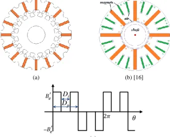
A classical IPM rotor structure is shown in Fig. 1(a) and the flux density in the air gap due to magnets is supposed to have roughly a rectangular distribution as shown in Fig. 1(b). For this classical structure, the ratio (Brotor)3/(Brotor)1=0.33, and the values of Gopt are given in Table II for different winding
topologies. A modification is carried out on the rotor structure for this topology in order to increase the third harmonic flux density in the air gap.
_
(a) (b)
Fig. 1. (a) IPM classic rotor structure. (b) Air gap flux density waveform. One approach consists in the introduction of holes in the rotor iron in the middle of the pole pitch in order to create a region where the flux density is weak (Fig. 2(a) and Fig. 2(c)). Another approach has been proposed in [16]: small radial magnets are added to the magnet poles (Fig. 2(b)).
(a) (b) [16]
_
Dp
Dt
(c)
Fig. 2. DP rotors (a) with holes (b) with extra magnets (c) simplified air gap flux density wave.
In this paper, a simple analytical sizing is developed for the first solution with holes. A ratio χrotor is defined as follows:
t rotor p D D (8)
where Dt resp. Dp is the opening angle of the holes (resp. of
poles) as shown in Fig. 2(c).
The first and the third harmonic of flux density in the air gap can be expressed as:
1 ' 4 1 sin 2 e rotor rotor B B (9)
3 ' 4 1 sin 3 3 2 e rotor rotor B B (10)where Be’ is the amplitude of flux density of PMs in the air gap.
In (9) and (10) Be’ can be derived as:
' (1 ) 2 1 1 a r e rotor e a e rotor S B S B S e a S (11)where Br, a are the remanence and thickness of the PMs; Sa, Se
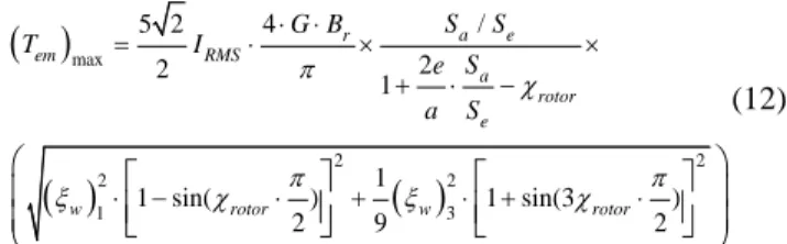
are the surfaces of the PMs and the air gap by pole; e is the air-gap. Substituting (6), (9) (10) and (11) to (3), the maximum torque can be derived as follows:
max 2 2 2 2 1 3 / 4 5 2 2 2 1 1 1 sin( ) 1 sin(3 ) 2 9 2 a e r em RMS a rotor e w rotor w rotor S S G B T I S e a S (12)where G is a constant related to the machine structure and the number of coil turns per phase, which can be found in equation (6).
For a given geometry, equation (12) is a general approach which can be used to determine the optimal hole width maximizing the torque for a given winding topology characterized by the winding factors (ξw)1 and (ξw)3.
χrotor χrotor (a) (b)
Fig. 3. Evolution of maximum torque vs the ratio χrotor for (a)Spp=1 and (b) Spp=0.5.
In Fig. 3, for Spp=1 (resp. Spp=0.5), the curve giving the
variation of (Tem)max as a function of χrotor presents a maximum
for χrotor=0 (resp. 0.36), the related ratio (Brotor)3/(Brotor)1=0.33 (resp. 1.43), and the value of Gopt is then equal to 1.09 (resp.
2.04). It appears then that machines with Spp=1 are not
interesting candidates for bi-harmonic structure in comparison with machines with Spp=0.5
With Spp=0.5, the improvement by injecting third harmonic
current is significant (+104%) with a modified rotor in comparison with a classical rotor (+13,6% in Table II).
III. EDDY CURRENT ROTOR LOSSES
For machines rotating at high speeds, or more exactly at high frequencies (>400Hz), the losses by eddy currents in the rotor can become significant. They are another important criterion which must be taken into account in order to protect the rotor from demagnetization. In synchronous PM machines, the losses in both magnets and iron sheets of the rotor are the result of the asynchronous movement of the mmf harmonics. Compared with integer slot machines, the machines with concentrated tooth fractional slot have usually both odd and even harmonics [32]. The selection of the winding with convenient harmonics of mmf is then of importance. In [21] it is shown that, with a nine-phase machine, a higher number of freedom degrees, in comparison with a three-phase machine, makes possible to cancel undesirable mmf harmonics. More generally, an indicator is proposed in [29], [31] in order to compare the eddy current losses in the rotor for different slot/pole combinations:
2 2 2 2 2 1 sgn( ) h h eddy losses fund rotor
fund B p I B f B h h
(13)where Bfund, Bh are the amplitudes of the magnetic flux density
of the fundamental and of the h-th harmonic resulting from the mmf of the stator currents; frotor is the mechanical rotation
frequency; sgn is the sign of the harmonic movement (+1 formalizing the same direction as the rotor and -1 the opposite direction).
Supposing that all the slot/pole combinations have the same fundamental flux density Bfund, for a given rotor mechanical
rotational frequency frotor, the indicator of eddy current losses,
in the rotor of five-phase machines with concentrated tooth winding topology, is presented in Table III.
TABLEIII
Index of Eddy Current Losses for 5-Phase Machines
Ns/Np 2 4 6 8 10 12 14 16 18 5 70.7 420.7 682.4 671.6 / 549.1 472.5 575.6 367.5 10 / 15.9 46.8 106.2 / 169.2 182.0 167.4 133.5 15 43.3 11.7 7.1 38.9 / 47.3 59.6 65.0 75.0 20 / / 21.1 4.0 / 11.7 68.7 25.3 67.8 25 19.4 10.7 31.5 12.8 2.6 35.8 10.5 30.5 13.7 30 / 10.8 / 2.9 / 1.8 9.9 9.4 2.9 35 8.5 4.8 3.9 7.2 / 6.5 1.3 1.3 7.3 40 / / 3.4 / / 5.3 1.0 1.0 5.3
As in [29], it can be concluded from table III that among combinations with index below 5 (in green), those with Spp=0.5
are of smaller amplitude. They are therefore interesting potential candidates when high frequencies must be considered in the payload of the machine.
IV. FINITE ELEMENT VERIFICATION FOR THE PROTOTYPE In this section, the FE method, taking into account both the saturation effects, flux leakage, and the slot effects is used to verify the previous analysis.
Simultaneously considering the different criteria defined in sections II and III, the 40-slot/16-pole combination is chosen because:
Spp=0.5 guarantees low rotor losses at high speed when
the machine is supplied by the first harmonic only; A high value of winding factor 0.951 for the third
harmonic makes it possible to produce high torque values with reasonable current densities at low speed; A DP machine allows flexible control at high speed
when the maximum voltage is reached.
Table IV presents the main specifications of the 5-phase 40- slot/16-pole machine.
TABLEIV
Main Specifications of the Machine
Parameters Value
Stator diameter (mm) 95
Rotor diameter (mm) 64
Active length (mm) 115
Air gap length (mm) 1
PM thickness (mm) PM height (mm) Slot height (mm) 4 18 22
Fig. 4. DP machine with 5 phases/40 slots/16poles and its flux density distribution under MTPA control and current density of 10A/mm2
.
Fig. 4 shows the ¼ structure of the original double polarity machine with 5 phases, 40 slots, 16 poles, χrotor=36% and a flux
density distribution obtained by FE method. A. Flux of rotors (Φ1, Φ3)
0.0203
0.0082
(a) (b)
Fig. 5. FE validation with (a) magnetic flux in the air gap (b) harmonics. Fig. 5 shows the flux and its harmonic spectrum of one
phase in no-load condition. The 1st and the 3rd harmonic flux are dominant. The ratio between the first and the third harmonic flux Φ3/Φ1 is equal to 0.4 and the value of Gopt index to 1.58
according to (4).
B. Losses analysis
For the machines with tooth concentrated windings, one major concern is the eddy-currents losses. Table V displays different significant points obtained in the case of a bi-harmonic supply with a current density of 20 A/mm2. Even if the third harmonic frequency is from 200 Hz to 2000 Hz, the eddy-current losses are overcome.
It must be pointed out that the amplitude and phase of the two harmonics of current are obtained through the optimization process detailed in section VI, which consists of applying the MTPA strategy on the DP machine taking into account maximum peak voltage (35V as the maximum phase-to-phase peak).
TABLEV
Main Losses of Machine with Bi-harmonic Supply
N(rpm) 150 2000 4000 5000 3f(Hz) 200 800 1600 2000 I1(A) 128.0 195.63 194.69 194.4 1 (rd) 0 1.22 1.45 1.51 I3(A) 154.1 41.53 45.77 46.97 3 (rd) 0 1.53 1.6 1.62 T(Nm) 95.62 36.13 11.12 4.44 Umax(V)(PHASE TO PHASE PEAK) 34 35 35 35 P(kW) 2.5 7.56 4.65 2.32 PCU(W) 450 450 450 450 PIR(W) 16 44 94 136.6 PMAG(W) 0.19 1.4 1.44 1.7 (-) 0.85 0.94 0.9 0.8 V. EXPERIMENTAL VALIDATION
In order to proof the effectiveness of the concept of double-polarity PM machine, a prototype has been designed. Fig. 6 shows the stator and rotor of a 5-phase 40-slot/16-pole (and 48-pole) DP machine. In order to decrease the cogging torque and other torque ripples, the stator is skewed by ½ slot step. In the following part, thanks to vector control, it is shown the ability to produce torques of comparable amplitude and low ripple level with only the first or the third harmonic of current but also with both harmonics simultaneously (Fig. 8 to Fig. 10).
(a) (b)
A. Back EMF (E1, E3)
Fig. 7 gives the back-emf and the harmonic spectrum at 500 rpm speed. The back-emf third harmonic term is greater than the fundamental, because of a high value of winding factor, but both have comparable magnitude (E1/E3=0.82).
The maximal torque can be derived using (3). According to the FE results, the ratio ropt, giving the optimal distribution ratio
between the injected currents I1 and I3, can be calculated:
ropt= 0.64 and Gopt=1.57. The torque characteristics are
analyzed using this distribution ratio in the following part.
(a) (b)
Fig. 7. (a) back-EMF at no-load (b) harmonics.
B. Torque Characteristics
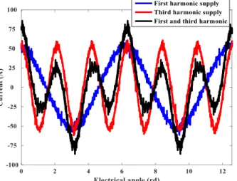
A comparison is made between the torque calculated with FE method and the one measured using the machine prototype. The two approaches are with MTPA control strategy. In order to validate the particular functionality of this DP machine, the torques are evaluated under three kinds of supply: with the first only, third only or both first and third sinusoidal currents as shown in Fig. 8.
Fig. 8. For a given 35A RMS current value, experimental phase currents for the three MTPA supplies (first, third and both harmonics)
In this case, the three supply strategies are with the same 35 A RMS value of current, and the ratio between the first and the third harmonic currents ropt is always equal to 0.64 with the
bi-harmonic supply.
With the currents imposed as in Fig. 8, Fig. 9 shows the waveforms of torques at low speed (100 rpm) with a current density of 5A/mm2. As expected, the torque under bi-harmonic current is 35% higher than this one obtained with only the third harmonic current and 57% higher than this one obtained with only the first harmonic current as predicted by Gopt.
For each supply the torque is obtained by three approaches: Experimental measurement with a torque sensor; 2D-Finite Element calculation (bi-dimensional FE) ; Analytical estimation by dot-product of emf and current
vectors
Fig. 9. For a given RMS value of current and three supplies, comparison of the torques: measured, FE calculated, analytically estimated
It can be observed that the average torques are in accordance between the experimental and estimated approaches. As the estimated torque is based on linear modeling considering a no-load emf, it can be expected that the predicted values are a little higher than those measured and those obtained from FE approach. With FE approach, higher ripples can be observed. It is normal since cogging torque is implicitly calculated with FE and neglected with the analytical approach. In case of experimental estimation with torque sensor, lower ripples are expected because of the bandwidth of the sensor and also because the FE approach is taking into account imperfectly the skewing of ½ slot. FE is a bi-dimensional modeling and the skewing has been considered by a decomposition of the machine in 10 elementary machines (length L/10, L being the stator length of the real machine) with a shift angle 0.45o between them. Anyway the precision of the torque sensor is not perfect for the estimation of torque ripple either because of its limited bandwidth and the low frequency fluctuations of the mechanical load.
Fig. 10. Comparison of the mean value of torque between measured values, estimated values and FE calculation.
Fig. 10 shows for a range of current from 5A to 35A RMS, a comparison between the mean values of torque with the same three approaches as in Fig. 9. The error is always less than 8%. It is verified that the torque obtained with the bi-harmonic supply is the sum of the two torques obtained with both sinusoidal currents. The Double Polarity functionality is verified with the possibility to produce the torque by one or two harmonics of currents.
VI. PERFORMANCE COMPARISON FOR THE PROTOTYPE WITH
24 SLOTS/16POLES THREE-PHASE MACHINE
As mentioned in the introduction, the main goal of this paper is to present elements of design for new fault-tolerant five-phase machines whose specifity is their ability to produce torque by the first and the third harmonic with equal contribution for each harmonic. Thanks to this feature, more choices for the control of the torque and current supply are possible, mainly above the base speed when the maximum voltage imposed by the voltage source inverter is reached. On the contrary, for the three-phase sinusoidal machines, flux-weakening appears the unique solution when the maximum voltage is reached.
By comparing with a three-phase machine, the aim of this paragraph is to show that this new kind of fault-tolerant machine is able to produce comparable performance as a no-fault-tolerant three-phase machine. Of course, both machines are operating with the same peak phase-phase voltage and current density.
Moreover, several considerations are taken into account in the design of an equivalent three-phase machine in order to obtain a fair comparison between the two considered machines:
The number of poles (16) of the three-phase machine is the same as the five-phase one in order to ensure the same supply frequency in both machines for the same rotation speed. This permits a fair comparison between the frequency-dependent losses induced in both machines;
The number of slots (24) for the three-phase machine is modified to conform the three-phase machine winding and keep the same Spp=0.5 as the five-phase one;
The two machines have the same external volume; The same copper volume is used in both machines in
order to obtain the same copper losses for a given current density. The differences due to the end windings are not considered;
The three-phase machine rotor is designed without holes, because they are useless in a three-phase machine which cannot make profit of the third harmonic of emf. Two air gaps can then be considered: the first one (1mm) is unchanged; the second one is larger (1.33mm) in order to obtain the same magnetic flux density in the air gap;
Both machines must have the same torque quality. Since the slot/pole combinations with Spp=0.5 have a
poor torque quality, stators in both machines are skewed by ½ slot step in order to obtain a smooth
torque in both machines.
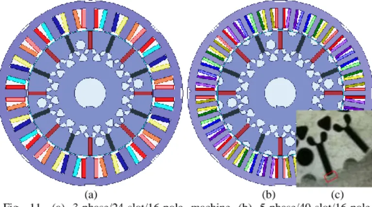
The number of turns is adapted in the three-phase machine in order to get approximately the same peak phase voltage as the five phase machine for the current density 5/Amm2, which corresponds to the steady state operation. Thus, 16 turns per coil for the five-phase and 18 for the three-phase machine are chosen. It can be noticed that this kind of three-phase machine with
Spp=0.5 are widely used in automotive applications [14]. Fig. 11
shows the topology of the three-phase and five-phase machines modeled using FE.
(a) (b) (c)
Fig. 11. (a) 3-phase/24-slot/16-pole machine (b) 5-phase/40-slot/16-pole machine (c) zoom of rotor before insertion of magnet
The performances of both machines are evaluated for the control strategy whose objective is to find the maximum torque delivered by the machine under voltage and current limits:
Concerning the voltage limit, both machines are fed by voltage source inverter (VSI) with DC-link voltage UDC=35V. This limit is included in the control strategy for both machines, and it corresponds to the maximum peak of phase-to-phase voltage;
Regarding the current limit, the comparison is performed considering three cases for the maximum allowed current density (5A/mm2, 10A/mm2 and 20A/mm2) under a verified constraint of maximum voltage limit. These values are considered to be representative respectively of steady state, mean transient (less than 30 minutes) and short transient (less than one minute) operations in an automotive traction machine.
The optimization problem to be solved is presented as follows:
* arg min
(
em( ))
x T x (14) with 12 1 1 max(U , ,U j, ,UN)UDC,n{3, 5} 2max, max {5,10, 20A / mm }
JJ J
where U1j is the phase-to-phase voltage between the phase n°1 and the phase n°j (j<n, n is the number of phases). Table VI gives the expression for each parameter in the optimization problem for both considered machines. The optimization problem developed in (14) is solved for three maximum current densities Jmax=5, 10 and 20A/mm2 for both machines. Once the
optimization problem is solved, the obtained optimal currents are injected into the FE model of both machines in order to
validate the analytical approach of optimization. In addition, experimental results are provided for the bi-harmonic five-phase machine for both Jmax=5A/mm2 and 10A/mm2 in
order to verify the analytical and the FE simulation predictions of torque/speed characteristics resulting from the resolution of the optimization problem.
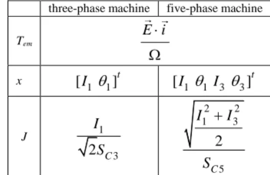
TABLEVI
Main Parameters for the Optimization Problem with SC3 and SC5, the Conductor Area.
three-phase machine five-phase machine
Tem E i x [ I1 1]t [ I11 I3 3]t J 1 3 2 C I S 2 2 1 3 5 2 C I I S
Finally, the comparison using analytical and FE simulations between the machines implicates the following main aspects:
Low speed torque capability: this part consists in comparing the delivered torque by the two machines at low speed (below the base speed);
Wide speed range capability: the aim is to compare the speed range above the base speed, in which both machines can deliver torque, knowing that the voltage constraint is active.
The peak current value and current density for each machine over the entire speed range.
The results of optimization presenting the comparison between the main aspects of the machines are given from Fig. 12 to Fig. 17.
The results in Fig. 12 show quite similar torque values between analytical and FE simulation for both three-phase and five-phase machine for all the considered current densities (5, 10 and 20A/mm2). The experimental tests carried out for the current densities Jmax=5A/mm2 and 10A/mm2 (see Fig.12 (a)
and (b))confirm the torque/speed characteristics predictions obtained analytically and by FE simulations for the five-phase bi-harmonic machine.
Fig. 12 depicted also the time domain waveforms of the phase current at two operations speed for both studied machines: one below the base speed and the other one above it. For the bi-harmonic five phase machine, the experimental ones are presented for Jmax=5A/mm2 and 10A/mm2 since experimental
tests are performed for these current densities. According to Fig.12, the three-phase machine is supplied by a sinusoidal current, while the bi-harmonic five phase machine is supplied by the first and the third harmonic current. In addition, the first and the third harmonic current amplitude I1 and I3 and the corresponding phase shifts θ1 and θ3 are varying in function of rotation speed which justifies the difference of the current shape between the low speed (below the base speed) and the high speed (above the base speed) as observed in Fig.12.
A. Comparison of the torque versus speed
Comparisons are provided between the maximum torque versus speed of the machines for different current densities. According to Fig. 12, in case of identical air gap value (1mm), it appears that the bi-harmonic machine is less interesting at low speeds (below the base speed). The results (analytical, FE and experimental) show that the three-phase machine produces 17%, 20% and 27 % more torque for Jmax=5, 10 and 20A/mm2
respectively. It is quite normal since the suppression of holes on the rotor structure for the three-phase machine has increased the air gap magnetic flux density, i.e. the peak value in an iron tooth of the three-phase machine (1.24T) is 13% higher than in the bi-harmonic machine (1.08T) shown in Fig. 13. On contrary, in the speed range above the base speed (when the voltage constraints are reached), the bi-harmonic machine can deliver higher torque with enlarged speed range. It must be pointed out that below the base speed the control is classical, with currents in phase with the electromotive force, sinusoidal or bi-harmonic waveforms (see Fig. 12). Above the base speed, the variation of the current shape for the bi-harmonic machine is due to the variation of the variables I1 and I3 and the corresponding phase shift θ1 and θ3 in order to satisfy the maximum peak of phase-to-phase voltage constraint. For the three-phase machine the current is still sinusoidal with only a shift with the emf.
These results give a proof of the interest of this new kind of machine since the five-phase machine is able to produce torque on wider speed range than the three-phase machine for the same peak voltage constraint. Consequently, the extension of torque/speed characteristics is the advantage that can be pointed out with the bi-harmonic machine. Thanks to the additional freedom degree which allows more choices for the control of the torque, the five-phase machine shows more efficient in the use of the VSI and a better potentiality than the three-phase machine to operate in the constant voltage speed range.
On the other hand, if the magnetic flux density is the same (see Fig. 13 with a 1.33mm air gap), then the torque/speed characteristics of both machines are more similar: the speed ranges of both machines are similar (around 6000 rpm) and lower torque at low speeds is obtained for the bi-harmonic five-phase machine as shown in Fig. 14 and Fig. 15. However, according to Fig. 15, the bi-harmonic machine is still advantageous when the voltage limits are reached (between the base speed and the maximum speed).
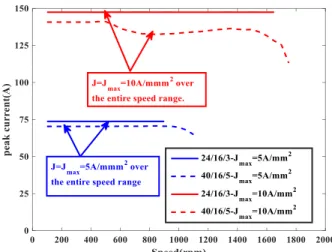
B. Peak current value comparison and current density
The reason of a wider speed range capability lies in the fact that in case of a bi-harmonic machine, the torque can be obtained with different combinations of two harmonics of current. As consequence for a given current density, different peak currents leading to different peak voltages can be obtained. With a three- phase machine this choice is impossible since the peak current is directly determined by the RMS current. In Fig. 16, it appears clearly for a three-phase machine that the peak current is constant when the surface current density is also constant. It is different for the bi-harmonic machine.
In the case of Jmax=20A/mm2 plotted in Fig. 17, it appears
that for the three-phase machine the current density must be reduced when the speed is increasing (over 500rpm) in order to respect the voltage limit. This is why the three-phase machine provides a lower torque at high speed as observed in Fig. 12(c). In other words, if the voltage source inverter is sized based on the five-phase machine voltage-ampere rating, the three-phase machine will not be able to produce higher torque.
In conclusion, flux-weakening appears as the unique solution for the three-phase machine to operate at high speed. For the five-phase bi-harmonic machine, other choices are possible to operate at high speed when the voltage limit is reached, while keeping the maximum allowed current density. Without reducing the current density as for three-phase machine, the five-phase machine can operate at high speed simply by changing the current repartition between the first and the third harmonic.
VII. CONCLUSION
In this paper, the concept of DP five-phase machines which are able to produce the same amplitude of torque either by first or third harmonic of current has been verified for a prototype.
In addition to the classical fault tolerance property, the five-phase bi-harmonic machine can benefit of its degrees of freedom in order to optimize the supply of the machine, it is then expected that the usual flux-weakening control imposed by voltage limitation will be alleviated. Amplitude and phase shift of voltage vector will be adapted. A few results have been presented in table V in order to prove that the torque can be obtained by both harmonics and that eddy-current losses are acceptable even with bi-harmonic supply. Low torque ripples have also been verified even with two harmonics. In order to allow the development of other DP machines, elements for the design of this kind of machine have been given: slot/pole combination with sufficient first and third winding factors, a special rotor configuration to redistribute flux between its 1st and 3rd harmonic and, especially when high frequencies are required, with a low eddy-current loss index.
Finally, in order to highlight the intrinsic difference with three-phase machine, a comparison has been achieved and experimental tests are carried out in order to confirm the analytical and the FE simulations predictions. The results confirm the interest of this new kind of bi-harmonic especially at high speed when the voltage limit is reached.
(a)
(b)
(c)
Fig.12. Torque speed characteristics for the three-phase and the five-phase machines calculated analytically, by FE and experimentally. (a) Jmax=5A/mm2.
Fig. 13. Magnetic flux density in the tooth for three-phase and five-phase machines calculated using FE simulations.
Fig. 14. Comparison of the delivered torque and the time domain current waveforms between the three-phase with 1.33 mm airgap and the five-phase machine with 1 mm airgap with J=5A/mm2.
Fig.15 Comparison of torque/speed characteristics between 24-slot/16-pole 3-phase machines with 1.33mm of airgap with the bi-harmonic machine.
Fig.16. Evolution of the peak current value and current density over the speed range for the three-phase and the five-phase machines with voltage constraints for Jmax=5A/mm2 and Jmax=10A/mm2.
Fig.17. Evolution of the peak current value and current density over the speed range for the three-phase and the five-phase machines with voltage constraints for Jmax=20A/mm2.
REFERENCES
[1] F. Barrero, M. J. Duran, “Recent Advances in the Design, Modeling and Control of Multiphase Machines—Part 1,” IEEE Trans. Ind. Electron., vol. 63, no. 3, pp. 449–458, Jan. 2016.
[2] R. Bojoi, A. Cavagnino, A. Tenconi, A. Tessarolo and S. Vaschetto, “Multiphase Electrical Machines and Drives in the Transportation Electrification,” in Proc. 2015 IEEE 1st International Forum on Research
and Technologies for Society and Industry Leveraging a better tomorrow (RTSI), Turin, 2015, pp. 205–212.
[3] H-M. Ryu, J-W. Kim, S-K. Sul, “Synchronous-Frame Current Control of Multiphase Synchronous Motor Under Asymmetric Fault Condition due to Open Phases,” IEEE Trans. Ind. Appl., vol. 42, no. 4, pp. 1062–1070, July-Aug. 2006.
[4] J. Wang, L. Zhou and R. Qu, “Harmonic Current Effect on Torque Density of a Multiphase Permanent Magnet Machine,” in Proc. 2011
International Conference on Electrical Machines and Systems (ICEMS),
Beijing, 2011, pp. 1–6.
[5] L. Parsa and H. A. Toliyat, "Five-Phase Permanent-Magnet Motor Drives,” IEEE Trans. Ind. Appl., vol. 41, no. 1, pp. 30–37, Jan.-Feb. 2005. [6] A. Abdelkhalik, M. Masoud and W. Barry, “Eleven-Phase Induction Machine: Steady-State Analysis and Performance Evaluation with Harmonic Injection,” IET Electr. Power Appl., vol. 4, no. 8, pp. 670–685, Sept. 2010.
[7] M. Mengoni, L. Zarri, A. Tani, L. Parsa, G. Serra, D. Casadei,“High-Torque-Density Control of Multiphase Induction Motor
Drives Operating Over a Wide Speed Range”, IEEE Trans. Ind. Electron., vol. 62, no. 2, pp.814–825, Feb. 2015.
[8] P. Z. Zhao and G. J. Yang, "Torque Density Improvement of Five-Phase PMSM Drive for Electric Vehicles Applications”, J. Power Electron., vol. 11, no. 4, pp. 401–407, 2011.
[9] K. Wang, Z. Q. Zhu, G. Ombach, “Torque Improvement of Five-Phase Surface-Mounted Permanent Magnet Machine Using Third-Order Harmonic”, IEEE Trans. Energy Convers., vol. 29, no. 3, pp.735–747, Sept. 2014.
[10] F. Scuiller, E. Semail, J.F. Charpentier, “Multi-criteria Based Design Approach of Multiphase Permanent Magnet Low-speed Synchronous Machines”, IET Electr. Power appl., vol.3, no. 2, pp.102–110, 2009. [11] S. Sadeghi, A. Mohammadpour and L. Parsa, “Design Optimization of a
High Performance Five-Phase Slotless PMSM”, in Proc. Power
Electronics, Electrical Drives, Automation and Motion (SPEEDAM),
2014 International Symposium on, Ischia, 2014, pp. 6–11.
[12] E. Levi, “Advances in Converter Control and Innovative Exploitation of Additional Degrees of Freedom for Multiphase Machines,” IEEE Trans.
Ind. Electron., vol. 63, no. 1, pp. 433–448, Jan. 2016.
[13] A. S. Abdel-Khalik, M. A. Elgenedy, S. Ahmed, and A. M. Massoud, “An Improved Fault-Tolerant Five-Phase Induction Machine Using a Combined Star/Pentagon Single Layer Stator Winding Connection,”
IEEE Trans. Ind. Electron., vol. 63, no. 1, pp. 618–628, Jan. 2016.
[14] A. S. Abdel-Khalik, S. Ahmed, and A. M. Massoud, "Dynamic Modeling of a Five-Phase Induction Machine with a Combined Star/Pentagon Stator Winding Connection," IEEE Trans. Energy Convers., vol. 31, no. 4, pp. 1645-1656, Dec. 2016
[15] Z. Q. Zhu, D. Wu and X. Ge, “Investigation of Voltage Distortion in Fractional Slot Interior Permanent Magnet Machines Having Different Slot and Pole Number Combinations,” IEEE Trans. Energy Convers., vol. 31, no. 3, pp. 1192–1201, Sept. 2016.
[16] B. Aslan, E. Semail, “New 5-phase Concentrated Winding Machine with bi-harmonic Rotor for Automotive Application,” in Proc. 2014
International Conference on Electrical Machines (ICEM), Berlin,
Germany, Sept. 2-5, 2014.
[17] H. Zahr, J. Gong, E. Semail, F. Scuiller, “Comparison of Optimized Control Strategies of a High-Speed Traction Machine with Five Phases and Bi-harmonic Electromotive Force,” Energies, vol. 9, no. 12, pp. 1–19, Dec. 2016.
[18] G. Dajaku, D. Gerling, “Low Costs and High Efficiency asynchronous machine with stator cage winding,” in Proc. 2014 IEEE International
Electric Vehicle Conference (IEVC), Florence, Italia, Dec. 17-19, 2014,
pp. 1–6.
[19] O. Moros, A. Patzak, D. Gerling, “Low Cost High Efficiency Traction Drivetrain According to the ISCAD Principle,” in Proc. 5th Conference
on Future Automotive Technology - Focus Electromobility (CoFAT-2016), Munich, Germany, May 03-04, 2016.
[20] F. Scuiller, H. Zahr, E. Semail, “Maximum Reachable Torque, Power and Speed for Five-Phase SPM Machine with Low Armature reaction”, IEEE
Trans. Energy Convers., vol. 31, no. 3, pp. 959–969, Sept. 2016.
[21] X. Chen, J. Wang, V. I. Patel and P. Lazari,“A Nine-Phase 18-Slot 14-Pole Interior Permanent Magnet Machine With Low Space Harmonics for Electric Vehicle Applications, ” IEEE Trans. Energy Convers., vol. 31, no. 3, pp. 860–871, Sept. 2016
[22] I. Boldea, L. N. Tutelea, L. Parsa, and D. Dorrell, “Automotive Electric Propulsion Systems with Reduced or no Permanent Magnets: An overview,” IEEE Trans. Ind. Electron., vol. 61, no. 10, pp. 5696–5711, Jan. 2014.
[23] A.M. El-Refaie, “Motors/Generators for Traction/Propulsion
Applications: A review”, IEEE Trans. Veh. Technol. Magazine, vol. 8, no. 1, pp. 90–99, March 2013.
[24] A.M El-Refaie, “Fractional Slot Concentrated Windings Synchronous Permanent Magnet Machines: Opportunities and Challenges,” IEEE
Trans. Ind. Electron., vol. 57, no. 1, pp.107–121, Jan., 2010.
[25] B. Aslan, E. Semail and J. Legranger, “General Analytical Model of Magnet Average Eddy-Current Volume Losses for Comparison of Multi-phase PM Machines with Concentrated Winding,” IEEE Trans.
Energy Convers., vol. 29, no. 1, pages. 11, March 2014.
[26] P. B. Reddy, A. M. El-Refaie, H. Kum-Kang, J. K. Tangudu, and T. M. Jahns, “Comparison of Interior and Surface PM Machines Equipped with
Fractional-Slot Concentrated Windings for Hybrid Traction
Applications,” IEEE Trans. Energy Convers., vol. 27, no. 3, pp. 593–602, May 2012.
[27] J. Gong, B. Aslan, E. Semail, F. Gillon, “High Speed Functionality Optimization of Five-Phase Machine Using 3rd Harmonic Current”,
COMPEL, vol. 33, no. 3, pp. 879–893, April 2014.
[28] J. Wang, X. Yuan, and K. Atallah, “Design Optimization of a Surface Mounted Permanent-Magnet Motor with Concentrated Windings for Electric Vehicle Applications,” IEEE Trans. Veh. Technol., vol. 62, no. 3, pp. 1053–1064, Nov. 2013.
[29] B. Aslan, E. Semail, J. Korecki, J. Legranger, “Slot/Pole Combinations Choice for Concentrated Multiphase Machines Dedicated to Mild-Hybrid Applications,” in Proc. 37th Annual Conference on IEEE Industrial
Electronics Society (IECON), Vienna, Austria, Nov. 10-13, 2013, pp
3698–3703.
[30] N. Bianchi,S. Bolognani,M. D. Pre,G. Grezzani, “Design Considerations for Fractional Slot Winding Configurations of Synchronous Machines,”
IEEE Trans. on Industry Applications, vol. 42, no. 4, pp.997–1006,
July-Aug. 2006.
[31] N. Bianchi, E. Fornasiero, “Index of Rotor Losses in Three-Phase Fractional-Slot Permanent Magnet Machines,” IET Electr. Power Appl., vol. 3, no. 5, pp.381–388, Sept. 2009.
[32] J. Pyrhonen, T. Jokinen, V. Hrabovcova, Design of Rotating Electrical
Machines, 1st edition, Wiley, Book, pp. 63–66, 2008.
[33] A. S. Abdel-Khalik, and S. Ahmed. “Performance Evaluation of a Five-Phase Modular External Rotor PM Machine with Different Rotor Poles,” Alexandria Engineering Journal, vol. 51, no. 4, pp 249–261, 2012.
[34] H. Kang, L. Zhou, J. Wang, “Harmonic Winding Factors and MMF Analysis for Five-Phase Fractional-Slot Concentrated Winding PMSM,” in Proc. International Conference on Electrical Machines and Systems
(ICEMS), Busan, Korea, Oct. 26–29, 2013.
[35] F. Scuiller, E. Semail J.F. Charpentier, “General Modelling of the Windings for Multi-Phase Machines - Application for the Analytical Estimation of Mutual Stator Inductance for Smooth Air Gap Machines,”
Eur. Phys. J. Appl. Phys., vol. 5, no. 3, pp. 135–151, 2010.
Jinlin Gong (M’13) received the B.Sc.
degree from the Southwest Jiaotong University, Chengdu, China, in 2006. He got the M.S degree from Southwest Jiaotong University and the engineering degree from Ecole Centrale de Lyon in 2008, and received the Ph. D degree in electrical engineering from Ecole Centrale de Lille, France, in 2011. From October 2011 to August 2012, he was an Assistant Professor at the Engineering School of Arts et Métiers ParisTech, Lille, France. Since Mars 2013, he has been an Assistant Professor with the School of Electrical Engineering of Shandong University, Jinan, China. His research interests include optimal design and control of linear motors and multiphase synchronous motors.
Hussein Zahr (SM’13) received the B.S. and M.S. degrees from the Faculty of engineering, Lebanese university and
Ecole Polytechnique de Nantes,
University de Nantes, and the Ph.D.
degree from the École Nationale
Supérieure des Arts et Metiers in 2016. He is currently postdoctoral researcher in electrical engineering at Ecole Nationale Superieure des Arts et Metiers(ENSAM), Laboratory of Electrical Engineering and Power Electronics of Lille (L2EP).
His current research interest includes design, modeling, and control of multiphase machines.
Eric Semail (M’02) graduated from the
Ecole Normale Supérieure, Paris, France, in 1986, and received the Ph.D. degree with a thesis entitled “Tools and studying method of polyphase electrical systems—Generalization of the space vector theory” from the University of Lille, France, in 2000. He became an Associate Professor at the Engineering School of Arts et Métiers ParisTech, Lille, France, in 2001 and a Full Professor in 2010. In the Laboratory of Electrical Engineering of Lille (L2EP), France, his fields of interest include design, modeling, and control of multiphase electrical drives (converters and ac drives). More generally, he studies, as a Member of the Control team of L2EP, multimachine and multiconverter systems. Fault tolerance for electromechanical conversion at variable speeds is one of the applications of the research with industrial partners in fields such as automotive, marine, and aerospace. Since 2000, he has collaborated on the publication of 33 scientific journals, 64 International Congresses, 5 patents, and 2 chapters in books.
Mohamed Trabelsi (M’16) received the B.S. and M.S. degrees in electrical engineering from the Ecole Superieure des Sciences et Techniques, University of Tunis, Tunis, Tunisia and the Ph.D. degree in electrical engineering jointly from the Aix-Marseille University, Marseille, France, and the Ecole Superieure des Sciences et Techniques, University of Tunis, in 2012. He is currently a Postdoctoral with Ecole Nationale Superieure des Arts et Metiers (ENSAM), Laboratory of Electrical Engineering and Power Electronics of Lille (L2EP), Arts et Metiers ParisTech, Lille, France. He is also an Associate Professor of electrical engineering with the
Ecole Nationale d’Ingenieurs de Sousse, ENISO, Sousse, Tunisia. His research interests include modeling, control, and diagnostics of conventional three-phase ac motor drives, power converters, and multiphase drives.
Bassel Aslan (M'12) received the M.S. degree in electrical engineering from Ecole Normale Supérieure, University Paris 11, France, in 2009, and the Ph.D. degree in electrical engineering with specialization in electrical machines design for hybrid vehicles from Arts et Métiers ParisTech, France, in 2013. Since
2010, he worked with different
automotive suppliers and vehicles constructors, Valeo, Ferrari, with main design and development activity of high performance alternators and electrical machines for automotive application. His research interests include the design of multiphase machines with concentrated winding, besides control and power electronics to ensure optimal machine capacity exploitation. Currently, he is involved in studying structures of high efficiency and high power density compatible with motorsport and aeronautical applications.
Franck Scuiller (M'11) received the Electrical Engineering degree (M.Sc. degree) from ENSIEG, INPG (Grenoble National Polytechnic Institute) in 2001 and the Ph.D. degree from Arts et Metiers ParisTech in 2006. In 2007, he was a lecturer in French Naval Academy. From 2008 to 2011, he was a technical project manager in warship electric power systems for DCNS company (Lorient, France). Since September 2011, he is an Associate Professor in Electrical Engineering in the French Naval Academy. His research interest is multi-phase machines for marine applications (ship propulsion, marine current turbine).