Journal of Colloid and Interface Science Volume 447, 1 June 2015, Pages 240–247
Nano-micro structured superhydrophobic zinc coating on steel for prevention of corrosion and ice adhesion
J.D. Brassarda, , , D.K. Sarkarb, J. Perrona, A. Audibert-Hayetc, D. Melotc a Anti-icing Materials International Laboratory (AMIL), Université du Québec à
Chicoutimi, 555 Blvd. Université, Chicoutimi (Saguenay), Québec G7H 2B1, Canada b Centre Universitaire de Recherche sur l’Aluminium (CURAL), Université du Québec à Chicoutimi, 555 Blvd. Université, Chicoutimi (Saguenay), Québec G7H 2B1, Canada c TOTAL, 2, place de la Coupole – La Défense 6, 92078 La Défense Cedex, Paris, France
Received 29 September 2014, Accepted 29 November 2014, Available online 6 December 2014
doi:10.1016/j.jcis.2014.11.076 Abstract
Thin films of zinc have been deposited on steel substrates by electrodeposition process and further functionalized with ultra-thin films of commercial silicone rubber, in order to obtain superhydrophobic properties. Morphological feature, by scanning electron microscope (SEM), shows that the electrodeposited zinc films are composed of micro-nano rough patterns. Furthermore, chemical compositions of these films have been analyzed by X-ray diffraction (XRD) and infra-red (IRRAS). An optimum
electrodeposition condition, based on electrical potential and deposition time, has been obtained which provides superhydrophobic properties with a water contact angle of 155 ± 1°. The corrosion resistance properties, in artificial seawater, of the
superhydrophobic zinc coated steel are found to be superior to bare steel. Similarly, the measured ice adhesion strength on superhydrophobic surfaces, using the centrifugal adhesion test (CAT), is found to be 6.3 times lower as compared to bare steel. This coating has promising applications in offshore environment, to mitigate corrosion and reduce ice adhesion.
Keywords
Superhydrophobic, Zn electrodeposition, Nanostructures, Corrosion resistance, Icephobic, Ice adhesion
1. Introduction
The offshore explorations for mining in the northern territories are now more active than before, though these areas are concerned by harsh weather conditions. As buildings and equipments made in this region mainly use steel, the two major concerns are corrosion and ice adhesion. Industries as well as governments are paying billions of dollars to maintain the buildings in these harsh environments. Heavy ice accumulations cause major structural problems that increase the high level of danger for workers. The most common deicing methods are efficient but costly and require human resources
[1] and [2]. However, the passive methods, such as icephobic coatings, where ice does not adhere, needs fewer infrastructures and may reduce the amount of energy needed to remove the ice [3] and [4].
As the superhydrophobic surfaces repel water, these surfaces can be ideal for both anti-corrosion and icephobic applications for structures and buildings made with metals, particularly steel. Recently, we have shown that copper surfaces can be protected against 3.5 wt.% salt water as compared to the as-received copper [5]. It has also been found in the literature that superhydrophobic surfaces on other metal pieces show good anti-corrosion properties [5], [6], [7], [8], [9] and [10]. He et al. [11] and [12] show that a superhydrophobic surfaces become hydrophobic at lower temperature. Evidently, literatures claim that superhydrophobic surfaces are not always good for the application of reduced ice adhesion [13], [14] and [15]. However, it can also be found in the
literature that the superhydrophobic surfaces can reduce ice adhesion [16], [17], [18], [19], [20], [21], [22], [23], [24], [25], [26], [27] and [28]. Therefore, plenty of opportunities exist to vary the surface chemical composition as well as the morphology, to understand the superhydrophobic properties and their roles on ice adhesion.
A surface is said to be superhydrophobic when it has the ability to repel water. Scientifically, a surface that has a water contact angle more than 150°, with roll off properties, is called superhydrophobic.
The ability to repel water is a well-known phenomenon that occurs frequently in nature. Several insects and plants possess this ability. Among them, the most studied and well understood surface is the lotus leaf, the symbol of purity. The lotus leaf has been observed through a scanning electron microscope by Neinhuis and Barthlott [29]. They found that the surface of the lotus leaf is not very smooth, as believed, due to non-wetting properties, but rather rough, due to the co-existence of both micro and nano patterns. They also observed that these motifs are also covered with a low surface energy waxy material [29]. The patterned surface allows the air entrapment, and the wax inhibited the possible interaction with the water. These two characteristics are crucial parameters to obtain the superhydrophobic surfaces. Wenzel [30] as well as Cassie– Baxter [31] proposed two mathematical models to explain the wetting phenomena on rough surfaces that leads to superhydrophobic properties.
In the Wenzel model [30], the water drop penetrates the surface irregularities. Mathematically, Wenzel’s equation is written as
c o sθ′= Rwc o sθ ( 1 )
where the roughness factor Rw is the ratio of the true and apparent (geometric) surface
areas. According to the Wenzel model, when the true contact angle θ of water on a
smooth surface is less than 90°, the apparent contact angle θ′ is less than the true contact angle θ on a rough surface, and when the true contact angle θ is greater than
90°, the apparent contact angle θ′ is greater than the true contact angle θ, on a rough
surface.
The Cassie–Baxter model [31] describes the effect of roughness on chemically
heterogeneous structures where the apparent contact angle is mathematically derived from Cassie’s equation as follows:
c o sθ′= f1c o sθ1+ f
2c o sθ2 (2)
where θ′ is the apparent contact angle of the composite coating consisting of two
components with contact angles θ1 and θ2, and corresponding area fractions f1 and f2. In
such a composite system f1 is assumed to be the solid surface and f2 is assumed to be air where θ2 is 180° and as f1 + f2 = 1, Eq. (2) can be written as
c o sθ′= f1( c o sθ1+ 1 ) - 1 ( 3 )
This equation explains that on a rough surface with large amounts of air entrapment, in the surface irregularities, one can achieve a highly superhydrophobic surface with a very small area fraction f1 of the surface in contact with the water drop. The configuration leads to a very high contact angle and a very low contact angle hysteresis leading to the rolling-off of water drops on the contacting solid.
Accordingly to the Cassie–Baxter model, a water drop on a pattern surface (e.g. surface of a lotus leaf) will be in contact with a very little solid fraction and rest on the entrapped air into the pattern that effectively increases the water contact angle more than 150°. Because the contact between water and the solid surface is less, the superhydrophobic surfaces can improve the ability of the coatings into corrosive environment and also decrease the ice adhesion over those surfaces.
Having lower electrochemical potential of zinc as compared to iron, layers of zinc are widely used in the industries as a sacrificial layer to protect steel against electrochemical corrosion. The object of this work is to prepare superhydrophobic thin films of zinc on steel substrates for improved protection against corrosion as compared to as-coated steel, as well as study the ice adhesion reduction properties on these surfaces.
2. Experimental
2.1. Materials and methods
Steel plates with a 1 mm thickness were cut to 50 mm by 20 mm rectangular pieces and used as the substrates. They were further polished using 120 and 320 grit sand papers and subsequently washed in an ultrasonic water bath for 15 min. The ultrasonically cleaned steel substrates were then chemically cleaned for 30 s in a 0.1 M HNO3 solution to remove surface oxides and hydroxide. These substrates were immediately rinsed and used for electrodeposition of zinc.
The electrodeposition process was conducted in a three-electrodes system (PGZ100 potentiostat). The system consists of steel as the working electrode, platinum as the counter electrode and silver/silver chloride as the reference electrode. The
electrochemical bath was prepared by dissolving 0.1 M Zinc Chloride (ZnCl2) and 0.01 M Zinc Nitrate (Zn(NO3)2) in water, following the work of Kazuhiko and Shinji [32]. The pH of the solution was adjusted to 2.0 using nitric acid (HNO3). The deposition of zinc was conducted at a constant voltage of −1400 mV for a time range of 0–15 min. These zinc coated samples were dried in an oven at 70 °C for 10 h.
The surfaces of the zinc coated steel substrates were then spray coated with room temperature vulcanized (RTV) silicone polymer (MG chemicals). The concentration of the silicone polymer was 5 wt.% in toluene. The silicone functionalized samples were then dried in similar conditions prior to characterization. The thin films were analysed via a scanning electron microscope (SEM, JEOL JSM-6480 LV) for morphological analysis. The X-ray diffraction (XRD) analysis of these samples was carried out using a Bruker D8 Discover system. Fourier Transform Infrared spectroscopy (IRRAS) was used to
evaluate the atomic bonding in the films. IRRAS (Nicolet 6700 FT-IR) is equipped with a Mid-IR MCT-A N2-cooled detector and a KBr beam splitter. The wetting properties of the substrates were performed by measuring static contact angles and contact angle
hysteresis (Krüss contact angle goniometer) at five positions on each substrate using a 5 µL deionized water drop.
The corrosion resistance of the substrates was investigated via potentiodynamic polarization curves acquired by electrochemical experiments in a 3.5 wt.% of sodium chloride (NaCl) solution in water, representing the corrosive environment of seawater. Open circuit potential (OCP) and polarization time studies for all samples were 30 min and approximately six minutes respectively. Electrochemical experiments were
performed using a PGZ100 potentiostat and a 300 cm3 – EG&G PAR flat cell (London Scientific, London, ON, Canada), equipped with a standard three-electrode system with
an Ag/AgCl reference electrode, a platinum mesh as the counter electrode, and the sample as the working electrode. The samples prepared in one condition were evaluated three times. The Tafel curves were used to determine the corrosion resistance of each substrate.
The ice adhesion properties of the substrates were evaluated using the centrifuge adhesion test [33] and [34]. The test, developed at the Anti-icing materials international laboratory, is well mastered, steady and repeatable. It consists of nine beams
simultaneously iced with freezing drizzle with a mean volumetric diameter, MVD, of about 320 µm, at −8 °C. The accreted ice has a thickness of ∼5.6 mm and has a density of 0.87 g/cm3. Each beam is weighed and the ice surface is measured individually. Each beam is tested in the centrifuge apparatus in the same climatic cold-room at −10 °C. The centrifuge apparatus rotates the beam at increased speeds from 0 to the detachment speed at a constant and controlled acceleration of 300 rpm/s. The shear stress is measured following:
F = m rω2 ( 4 )
where
F = centrifugal force (N) m = mass of ice (kg) r = radius of the beam (m)
ω = speed of rotation (rad/s)
From the centrifugal force, the bulk shear stress is determined using:
(5)
where
A = iced area (m2)
τ = shear stress (Pa)
To compare the coatings to the reference substrate, steel for this study, an adhesion reduction factor is calculated. The adhesion reduction factor (ARF) consists of:
(6) The ARF over steel substrates is 1. When the factor is less than 1, the ice adhesion is more than the steel. When the factor is more than 1, the ice adhesion is less. The higher is the factor, the more the surface is icephobic.
3. Results and discussion
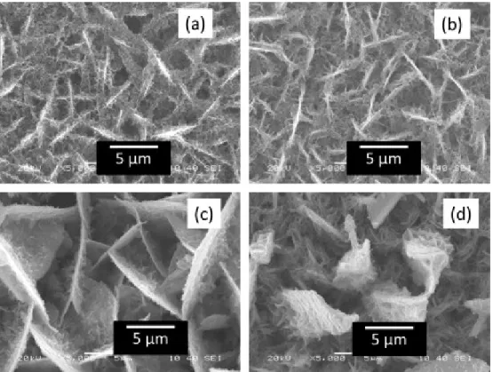
Fig. 1 shows the SEM images of electrodeposited zinc coated steel substrates at a potential of −1400 mV. Fig. 1(a)–(d) are the surfaces of Zn coated for 2, 5, 10 and 15 min, respectively. It is clear from these figures that the morphology of the zinc coated surfaces change with the deposition time, though they have a fractal nature. Fig. 1(a) and (b) shows the coated Zn surfaces are very compact. On the other hand, Fig. 1(c) shows the zinc films contain several holes. These holes are filled with air. According to the Cassie–Baxter model [31], a water drop can rest partially on the solid surface and partially on the air. An analysis of these images shows that the fraction of solids (f1-factor of Eq. (3)), are 0.3, 0.24, 0.18 and 0.19 respectively. Berger et al. [35] and Baik et al. [36] showed similar structures of pure Zn from ZnCl2 solutions on steel substrates. It is important to mention that while increasing the deposition time, the Zn films flack off from the steel substrates.
Fig. 1. The SEM images of Zn-surfaces on steel substrate in varying deposition time with deposition potential of −1400 mV. The electrodeposition time is (a) 2 min, (b) 5 min, (c) 10 min, (d) 15 min.
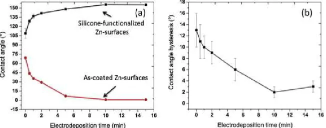
The effect of morphology on the surface wetting was studied. Fig. 2(a) shows the water contact angles on both zinc coated steel surfaces as well as silicone-functionalized Zn-surfaces. The contact angle on the chemically cleaned polished steel surfaces was found to be 69 ± 2°. However, water contact angle reduced to 44 ± 2° after depositing zinc for one minute. It was observed that water contact angle reduces with the increase of coating time. The water contact angle drastically reduces to 7 ± 1° for the zinc films deposited for 5 min. As it can be seen from the bottom curve of Fig. 2(a), the water
contact angle reduces to around 2 ± 1° on the zinc surfaces coated for 10 min. Similarly, 15 min-coated surfaces also show the water contact angle of around 3 ± 1°. The
reduction of the water contact angle on the zinc coated surfaces can be explained by the Wenzel model. Metals having high surface energy show water contact angles less than 90° on a smooth surface [37]. Evidently, increasing the surface roughness as shown in the SEM images of Fig. 1, the r factor of the Wenzel model increases and hence the water contact angle reduces on the zinc coated steel substrates.
Fig. 2. Wetting properties of Zn surfaces on steel substrates. (a) Contact angle of as-coated Zn surfaces (bottom) and silicone-functionalized Zn-surfaces (top) and (b) contact angle hysteresis silicone-functionalized Zn-surfaces.
The top graph of Fig. 2(a) shows the water contact angle on silicone-functionalized Zn surfaces on steel substrates. It has been observed that the water contact angle
increases with the increase of coating time of zinc. It can be observed that the variation of water contact angle on the silicone-functionalized Zn surfaces, graph on the top of Fig. 2(a), has the inverse behaviour as compared to the water contact angle only as-coated zinc surfaces (bottom curve of Fig. 2(a)). The silicone-functionalized steel substrate shows a contact angle of 109 ± 8°. The contact angle increased to more than 155 ± 1° when the zinc film was deposited for 10 min, and it also remains the same for the films deposited for 15 min. According to this curve, the optimized zinc coated time is considered to be 10 min, which provides a maximum water contact angle. Fig. 2(b) shows the contact angle hysteresis (CAH) on the silicone-functionalized Zn-surfaces. The CAH is found to be 13 ± 3° on the silicone functionalized steel substrates. However, the CAH reduced to 2 ± 1° on the silicone functionalized Zn substrates that was coated for 10 min. Evidently, this surface shows roll off properties of water drop.
The behaviour of water contact angle on silicone functionalized Zn surfaces follows the Cassie–Baxter model as mathematically depicted in Eq. (3). Brassard et al. [38]
previously showed with a model that the fluorinated silica nanoparticles also follows the Cassie–Baxter model [31]. They have shown the roughness of the silica nanoparticle films is proportional to the air fraction and that water contact angle increases with the increase of the roughness of the films due to the increase of the silica nanoparticles. They have measured the roughness of the films by optical profilometer. Since zinc coated steel surface is very black and light does not reflect from the films, it was not
possible to determine the roughness of the films such as Brassard et al. However, the SEM images of Fig. 1 show that the solid fraction of the film changes with the deposition time. The SEM images of Fig. 1 were used to calculate the solid fraction (f1 of Eq. (3)), assuming water drops rest on the crest of the surface structure. The formation of the crest is highly prominent in Fig. 1(c). Table 1 summarizes the solid fraction (f1),
calculated contact angle using f1 in Eq. (3) and measured contact angle. It is found that the f1 factor got a minimum value when the zinc film was deposited for 10 min, evidently, the calculated contact angle was found to be 151.5°. It can be noted that the measured contact angle in this case is 155 ± 1°. The error of the measured and calculated CA of only 2.7% shows that the calculated f1 factor from the SEM image is very precise. This precision is maintained for all four samples satisfactorily as the error of measured and calculated CA is below 3%, as given in Table 1. From the calculated CA in Eq. (3), it can be concluded that the water contact angle in this system follows the Cassie–Baxter model [31].
Berger et al. [35] have used silicone elastomer to modify the chemical nature of
electrodeposited zinc on steel. They have used a spin-coating method to prepare thick films of silicone. The water contact angle on their prepared surfaces show a maximum 108° as the layer of silicone was very thick. The effect of surface topography was hindered due to the thick layer of silicone layer. On the other hand, the layer of silicone layer was very thin and the topography of zinc layer was not changed, as observed in Fig. 4(c) and (d).
Zhao et al. [39] and Safaee et al. [40] show that organic acid passivated silver surfaces on ITO and copper substrates, respectively, show superhydrophobic properties and can reach a maximum by controlling the deposition time as we have shown in the zinc coated steel substrates case.
The optimized superhydrophobic Zn-surface was analyzed by XRD and FTIR to determine the composition of the surface, the results are shown in Fig. 3. Fig. 3(a) shows the XRD pattern of the zinc coated steel substrates. The four main characteristic diffraction peaks of zinc are found at 36.3°, 38.9°, 43.2°, 54.3° corresponding to the plans of Zn [0 0 2] Zn [1 0 0] Zn [1 0 1] Zn[1 0 2] for the hexagonal crystal structure of zinc [41]. Baik and Fray [36] have observed these four characteristic peaks of
Fig. 3(b) presents an absorbance IR spectrum of the silicone-functionalized Zn-surface. The manufacturer of the RTV silicone specified that it contains mainly three different molecules: trimethoxymethylsilane, hexamethyldisilazane and
octamethylcyclotetrasiloxane. The peaks at 800 and 1100 cm−1 correspond to the asymmetric stretching vibration of Si–O–Si group [38] and [42]. A peak approximately at
1145 cm−1 is due to the Si–O–C bond. Two peaks at 1150 and 910 cm−1 are due to Si–N bondings [43]. The peaks at 1400, 2950 and 3000 cm−1 were assigned to –
CH3[38] and [42] as silicone contains plenty of methylated groups (–CH3). The presence of –CH3 as well as –CH2 together reduces the surface energy and enhances the water contact angle to a surface that leads to the superhydrophobic properties.
Four different surfaces were chosen to perform the comparative studies on the corrosion and ice adhesion. The four surfaces are presented in Fig. 4. Some of the figures are the same as discussed before. Fig. 4(a) shows the polished and chemically clean steel surface and Fig. 4(b) is the silicone functionalized steel surface prepared in similar conditions. It is important to mention that they are not mirror polished to minimize the time, as this project is related to the industrial development of coatings against corrosion and ice adhesion. Therefore, existence of scratches on the surfaces is visible on both surfaces. Fig. 4(c) is the same as Fig. 1(c), the zinc films coated for 10 min. Fig. 4(d) is the silicone functionalized Zn surfaces as presented in Fig. 4(c). It is also important to mention that the coating of the RTV-silicone is very thin so that it does not modify the morphology of the steel surface as well as the zinc films as shown in Fig. 4(b) and (d). The inset of Fig. 4 shows the image of water drops as obtained from contact angle goniometer. It can be observed that the water contact angle on the steel surface is 69 ± 2°, inset of Fig. 4(a) that has been increased to 107 ± 8 °, inset of Fig. 4(b), after the functionalization with RTV-silicone. This enhancement of the contact angle is due to the presence of silicone on the steel surface that reduces the surface energy of steel. Fig. 4(c) shows the surface morphology of the zinc coated steel that was
electrodeposited for 10 min. The inset of this figure shows the shape of water drop. It is highly hydrophilic, providing a water contact angle below 1° due to the rough structure of high surface energy of zinc. Interestingly, the inset of Fig. 4(d) shows a water contact angle which is 155 ± 1 ° on the same zinc surface of Fig. 4(c) that was functionalized with RTV-silicone polymer. It is interesting to observe that the morphological feature of electrodeposited zinc of Fig. 4(c) does not change due to the functionalization of RTV-silicone polymers as shown in Fig. 4(d).
Fig. 5 shows the potentiodynamic curves of the bare steel surface, silicone functionalized steel surface, nano-micro structured zinc coated steel surface and Silicone functionalized nano-micro structured Zn coated steel surface. The polarization curves, or the Tafel curves, for these samples, are used to determine the polarization resistance and the corrosion potentials of the samples. These results are also presented in Table 2.
The polarization resistance is an important parameter to evaluate the corrosion performance of materials as higher polarization resistance indicates better protection properties against corrosion [5]. The polarization curve of Fig. 5(a) is obtained from the bare steel surface. The analysis of this curve using the Stern–Geary equation [44] provides the polarization resistance of the bare steel surface as 1.5 ± 0.1 kΩ. However, the polarization resistance is increased to 13.1 ± 1.0 kΩ, due to the presence of non-conducting functionalized RTV-silicone on the steel surfaces, as calculated from the polarization curve of Fig. 5(b). The polarization resistance of nano-micro structured zinc is found to be very low (0.4 ± 0.1 kΩ) as calculated from Fig. 5(c), this might be due to the rough structure of zinc films and its pureness as found from the XRD. The
polarization resistance is increased to a maximum of 44.4 ± 1.6 kΩ for the
superhydrophobic films prepared with the silicone functionalized Zn surfaces. This enhancement of the polarization resistance is due to the superhydrophobic nature of the films originated from the nano-micropattern of zinc films in association with the
non-conducting silicone polymer. Liu et al. [45] shows that superhydrophobic zinc films can be obtained by passivating the zinc films with fluorinated silane by simple immersion process. They have also shown these surfaces are corrosion resistant against salt water like ours, however; they did not provide any polarization curve or polarization resistance to quantify the corrosion resistance properties. On the other hand, Li et al. [6] have shown that the polarization resistance of copper stearate film is 40 kΩ, very similar to our superhydrophobic nano-micro structured zinc films. Interestingly, Huang et al. [5] have shown that a copper surface can be electrochemically modified in an ethanolic solution of stearic acid to fabricate superhydrophobic copper stearate films. They have also shown that in an optimum condition, with a thicker film of copper stearate, due to longer time of electrochemical modification, the polarization resistance of the superhydrophobic copper stearate films could be as high as 1220 kΩ.
Apart from the polarization resistance, it was observed that the corrosion potential of zinc is −927 mV, much lower than steel, which is −389 mV. That explains why zinc is used to protect steel against electrochemical corrosion. The corrosion potential of the Silicone functionalized steel surface is found to be −310 mV. Interestingly, the
superhydrophobic zinc, as prepared from the functionalization of nano-micro structured zinc using RTV-silicone; showed the corrosion potential of −132 mV which is much more positive than nano-micro structured zinc surfaces as well as steel. These results show that the superhydrophobic zinc surfaces functionalized with silicone are highly protective against corrosion of steel. A model has been presented in Fig. 6 to show the variation of the corrosion potential of these four surfaces. The mechanism of the increase of
corrosion potential of the superhydrophobic silicone functionalized nano-micro structured zinc as compared to the hydrophobic silicone functionalized steel is not understood well. A possible reason of this potential enhancement might be the entrapped air in the silicone-functionalized zinc surface as compared to the silicone functionalized steel surface.
It can be seen in the literature that the most of the cases, the corrosion potential is more positive on the superhydrophobic surfaces as compared to the base metals (the
references support it). However, a few references including one of our recent
publications shows the corrosion potential is more negative on the superhydrophobic surface as compared to the base metals [5] and [46]. This change may be due to the formation of new composition on the surface like copper stearate in case of
electrochemical modification of copper [5].
Apart from the corrosion tests, the ice adhesion properties of these four surfaces were evaluated. The ice adhesion reduction factors (ARF), which is the ratio of shear stress of ice adhesion of a given surface with respect to a standard surface, as described in the experimental section, is presented in the bars diagram of Fig. 7 as well as in Table 2. This table also provides the information on the shear stress associated to the ice adhesion. Having the water contact angle of 69 ± 2°, the measured shear stress
between ice and the bare steel surface is found to be 0.617 ± 0.004 MPa. This stress is used as a reference to compare ice adhesion of other surfaces, by calculating the adhesion reduction factor (ARF). Meuler et al. [3] measured the ice adhesion with iced water columns over a steel substrate. Their steel substrate had a water contact angle of 86 ± 3°. They measured an ice adhesion on steel of 0.698 ± 0.112 MPa using a force transducer. Though the methods to measure ice adhesion are different between Meuler et al. and ours, a substantial similarity is observed on the strength of ice adhesion of bare steel substrates. The shear stress associated with the ice adhesion on the silicone functionalized steel surface is measured to be 0.127 ± 0.055 MPa. Consequently, the ARF of ice on silicone functionalized steel surface is calculated to be 5.1 as compared to the bare steel surface. The calculated ARF of ice on the nano-micro structured
hydrophilic Zn and the nano-micro structured superhydrophobic Zn surfaces, as
functionalized with silicone, are found to be 0.8 and 6.3 respectively. The ARF of these two surfaces have been calculated from the measured shear stress of
0.816 ± 0.113 MPa and 0.098 ± 0.012 MPa, respectively.
The ice adhesion on these four surfaces can be understood based on the surface morphology and surface chemistry. Fig. 4 shows the morphology and Table 2 provides the water contact angles on these four surfaces. Due to the relatively smooth surface of steel (Fig. 4(a)) as compared to rough nano-micro structured zinc surface (Fig. 4(c)), the shear stress of adhesion of ice on the steel surface is 0.617 ± 0.004, relatively lower than the shear stress of adhesion of ice on the nano-micro structured zinc surface of 0.816 ± 0.113. It can also be seen that the water contact angle on the steel surface is much higher than on the nano-micro structured zinc surface, hence the interaction of water consequently with ice, is lower on the steel surfaces as compared to the nano-micro structured zinc surfaces. The water contact angle on the silicone functionalized steel and silicone functionalized nano-micro structured Zn-surfaces are found to be 69° ± 2 and 155° ± 1, respectively; and their respective shear stresses are
0.127 ± 0.055 MPa and 0.098 ± 0.012 MPa. It was observed that the ice adhesion had an inverse relation with the water contact angle. Several reports are found in the literature on the studies of ice adhesion on surfaces [47] including superhydrophobic surfaces [3], [13], [17], [20], [21], [33], [48], [49], [50] and [51]. However, the adhesion of ice with the surface is not well understood. An attempt was made by Muler et al. to correlate the ice adhesion with the contact angle hysteresis rather than contact angle using the data from the literature [3]. Further works are in progress, in our laboratory, to gain in depth knowledge in this field.
To verify the durability of the silicone-functionalized Zn surface against icing, a series of five consecutive tests of icing and deicing have been performed. Fig. 8(a) and (b) presents the ice adhesion reduction factor (ARF) and the contact angle (CA) of the superhydrophobic silicone-functionalized zinc surface after each test. It can be seen that the initial (first test) ARF of 6.3 ± 1 reduced to 5 ± 1 at the second test and remained
stable from test three to test five. The same phenomena can be seen in Fig. 8(b) with the contact angle. Before the first ice test, the contact angle is 155 ± 2° and slightly decreased and then stabilized to 150 ± 3° after five tests. These tests confirm that the silicone-functionalized Zn-surface is durable against icing. Ghalmi and Farzaneh [52] performed icing–deicing test of a a superhydrophobic surface fabricated with PTFE particle incorporated anodized aluminium. After a series of icing–deicing cycles, they showed that the ice adhesion reduction factor (ARF) decreased from 2.2 to 2 and that the contact angle decreased drastically from 155° to 130°. These drastic changes of CA can signify that the PTFE incorporated anodized aluminum may not be very suitable in icing application. On the other hand, silicone-functionalized Zn surfaces the ARF is much higher and CA remain above 150°, making these surfaces more suitable in icing
applications.
4. Conclusions
A nano-micro structured superhydrophobic zinc coating on a steel substrate was developed by optimizing the electrodeposition time of zinc on steel. Furthermore, the surface of zinc functionalized steel when functionalized with RTV-silicone, to obtain superhydrophobic properties, was characterized. The optimized time of a zinc coating formation is found to be 10 min and the corresponding RTV-silicone functionalized surfaces provide a water contact angle of 155 ± 1°. This surface shows the polarization resistance, the measure of corrosion protection, of 44.4 kΩ as compared to 1.5 kΩ of as-received steel surface. Moreover, this surface shows an ice adhesion reduction factor of 6, as compared to ice adhesion on steel surface. Owing to superhydrophobic properties, the RTV-silicone functionalized surface of zinc on steel substrates shows both corrosion resistance and reduced ice adhesion properties with respect to bare steel.
Authors would like to thank TOTAL SA, France, for the funding, Mrs. C. Blackburn for performing the centrifuge ice adhesion tests, Dr. C. Laforte for discussions on ice adhesion tests and Mrs. Y. Huang for discussions on corrosion testing.
References
[1] J.L. Laforte, M.A. Allaire, J. Laflamme Atmos. Res., 46 (1998), pp. 143–158 [2] C.C. Ryerson, ERDC/CRREL TR-08-14, CRREL, 2008.
[3] A.J. Meuler, J.D. Smith, K.K. Varanasi, J.M. Mabry, G.H. McKinley, R.E. Cohen ACS Appl. Mater. Interfaces, 2 (2010), pp. 3100–3110
[4] N. Saleema, M. Farzaneh, R.W. Paynter, D.K. Sarkar J. Adhes. Sci. Technol., 25 (2011), pp. 27–40
[5] Y. Huang, D.K. Sarkar, D. Gallant, X.G. Chen Appl. Surf. Sci., 282 (2013), pp. 689– 694
[6] J. Li, X. Liu, Y. Ye, H. Zhou, J. Chen Appl. Surf. Sci., 258 (2011), pp. 1772–1775 [7] T. Ning, W. Xu, S. Lu Appl. Surf. Sci., 258 (2011), pp. 1359–1365
[8] N. Verplanck, Y. Coffinier, V. Thomy, R. Boukherroub Nanoscale Res. Lett., 2 (2007), pp. 577–596
[9] W. Xu, J. Song, J. Sun, Y. Lu, Z. Yu ACS Appl. Mater. Interfaces, 3 (2011), pp. 4404– 4414
[10] Q. Zhang, Y.R. Zhu, Z.Y. Huang Gaodeng Xuexiao Huaxue Xuebao/Chem. J. Chin. Univ., 30 (2009), pp. 2210–2214
[11] M. He, H. Li, J. Wang, Y. Song Appl. Phys. Lett., 98 (2011), p. 093118 [12] M. He, J. Wang, H. Li, Y. Song Soft Matter, 7 (2011), pp. 3993–4000
[13] J. Chen, J. Liu, M. He, K. Li, D. Cui, Q. Zhang, X. Zeng, Y. Zhang, J. Wang, Y. Song Appl. Phys. Lett., 101 (2012) 111603-3
[14] S. Jung, M. Dorrestijn, D. Raps, A. Das, C.M. Megaridis, D. Poulikakos Langmuir, 27 (2011), pp. 3059–3066
[15] M. Nosonovsky, V. Hejazi ACS Nano, 6 (2012), pp. 8488–8491
[16] L.B. Boinovich, A.M. Emelyanenko, V.K. Ivanov, A.S. Pashinin ACS Appl. Mater. Interfaces, 5 (2013), pp. 2549–2554
[17] A. Dotan, H. Dodiuk, C. Laforte, S. Kenig J. Adhes. Sci. Technol., 23 (2009), pp. 1907–1915
[18] P. Guo, Y. Zheng, M. Wen, C. Song, Y. Lin, L. Jiang Adv. Mater., 24 (2012), pp. 2642–2648
[19] Y. Huang, M. Hu, S. Yi, X. Liu, H. Li, C. Huang, Y. Luo, Y. Li Thin Solid Films, 520 (2012), pp. 5644–5651
[20] R. Jafari, R. Menini, M. Farzaneh Appl. Surf. Sci., 257 (2010), pp. 1540–1543 [21] S.A. Kulinich, M. Farzaneh Appl. Surf. Sci., 255 (2009), pp. 8153–8157 [22] D.K. Sarkar, M. Farzaneh J. Adhes. Sci. Technol., 23 (2009), pp. 1215–1237
[23] S.L. Sivas, B. Riegler, R. Thomiaer, K. Hoover Silicone-Based Icephobic Coating for Aircraft, vol. 5NuSil Technology Newsletter (2008) 7 p.
[24] A.I. Abdulagatov, Y. Yan, J.R. Cooper, Y. Zhang, Z.M. Gibbs, A.S. Cavanagh, R.G. Yang, Y.C. Lee, S.M. George ACS Appl. Mater. Interfaces, 3 (2011), pp. 4593–4601 [25] T. Ishizaki, Y. Masuda, M. Sakamoto Langmuir, 27 (2011), pp. 4780–4788
[26] A.V. Rao, S.S. Latthe, S.A. Mahadik, C. Kappenstein Appl. Surf. Sci., 257 (2011), pp. 5772–5776
[27] X. Yonghao, L. Yan, W.H. Dennis, C.P. Wong Nanotechnology, 21 (2010), p. 155705
[28] D. Yu, J. Tian, J. Dai, X. Wang Electrochim. Acta (2013) [29] C. Neinhuis, W. Barthlott Ann. Botan., 79 (1997), pp. 667–677 [30] R.N. Wenzel Ind. Eng. Chem., 28 (1936), pp. 988–994
[31] A.B.D. Cassie, S. Baxter Trans. Faraday Soc., 40 (1944), pp. 546–551 [32] M. Kazuhiko, N. Shinji, Patent: 5,283,131, 1992.
[33] G. Fortin, A. Beisswenger, J. Perron Centrifuge adhesion test to evaluate icephobic coatings 2nd AIAA Atmospheric and Space Environments Conference, AIAA, Toronto, ON (2010)
[34] C. Laforte, IWAIS XI, 2005.
[35] F. Berger, J. Delhalle, Z. Mekhalif Electrochim. Acta, 54 (2009), pp. 6464–6471 [36] D.S. Baik, D.J. Fray J. Appl. Electrochem., 31 (2001), pp. 1141–1147
[37] D. Quéré Rep. Prog. Phys., 68 (2005), p. 2495
[38] J.D. Brassard, D.K. Sarkar, J. Perron Appl. Sci., 2 (2012), pp. 453–464 [39] N. Zhao, F. Shi, Z. Wang, X. Zhang Langmuir, 21 (2005), pp. 4713–4716
[40] A. Safaee, D.K. Sarkar, M. Farzaneh Appl. Surf. Sci., 254 (2008), pp. 2493–2498 [41] JCPDS 00-04-0831.
[42] J.D. Brassard, D.K. Sarkar, J. Perron ACS Appl. Mater. Interfaces, 3 (2011), pp. 3583–3588
[43] C. Iacob, J.R. Sangoro, P. Papadopoulos, T. Schubert, S. Naumov, R. Valiullin, J. Karger, F. Kremer PCCP, 12 (2010), pp. 13798–13803
[44] M. Stern, A.L. Geary J. Electrochem. Soc., 104 (1957), pp. 56–63
[45] H. Liu, S. Szunerits, W. Xu, R. Boukherroub ACS Appl. Mater. Interfaces, 1 (2009), pp. 1150–1153
[46] G. Momen, M. Farzaneh Appl. Surf. Sci., 299 (2014), pp. 41–46 [47] D.K. Sarkar J. Adhes. Sci. Technol., 26 (2012), pp. 407–411
[48] L. Foroughi Mobarakeh, R. Jafari, M. Farzaneh Appl. Surf. Sci., 284 (2013), pp. 459–463
[49] R. Menini, M. Farzaneh Surf. Coat. Technol., 203 (2009), pp. 1941–1946 [50] G. Momen, M. Farzaneh Appl. Surf. Sci., 258 (2012), pp. 5723–5728
[51] T. Bharathidasan, V. Kumar, M. Bobji, R. Chakradhar, B.J. Basu Appl. Surf. Sci., 314 (2014), pp. 241–250