CARACTÉRISATION DU CANAL DE PROPAGATION BAN D ANS UN MILIEU MINIER
MÉMOIRE PRÉSENTÉ À L'UNIVERSITÉ DU QUÉBEC EN ABITIBI-TÉMISCAMIN GUE COMME EXIGENCE PARTIELLE DE LA M AÎTRISE
EN INGÉNIERIE
PAR
MR MOULA Y ELHASSAN ELAZHA RI
Mise en garde
La bibliothèque du Cégep de l’Témiscamingue et de l’Université du Québec en Abitibi-Témiscamingue a obtenu l’autorisation de l’auteur de ce document afin de diffuser, dans un but non lucratif, une copie de son œuvre dans Depositum, site d’archives numériques, gratuit et accessible à tous.
L’auteur conserve néanmoins ses droits de propriété intellectuelle, dont son droit d’auteur, sur cette œuvre. Il est donc interdit de reproduire ou de publier en totalité ou en partie ce document sans l’autorisation de l’auteur.
Warning
The library of the Cégep de l’Témiscamingue and the Université du Québec en Abitibi-Témiscamingue obtained the permission of the author to use a copy of this document for non-profit purposes in order to put it in the open archives Depositum, which is free and accessible to all.
The author retains ownership of the copyright on this document. Neither the whole document, nor substantial extracts from it, may be printed or otherwise reproduced without the author's permission.
This thesis is dedicated to
MyMother
MyWife
And
First and the foremost, 1 praise Almighty Allah and thank Him for bestowing His blessings upon me and enabling me to complete this work.
1 also would like to thank my supervisor Professor Mourad Nedil for his support, resources, and guidance that he provided me during this work. 1 was especially touched by the kindness and the high ethics ofprofessor Nedil.
Professors Khalida Ghanem and lsmail Ben Mabrouk have provided valuable inputs and gave me much appreciated directions during my papers redactions; 1 thank them a lot for their help and look forward to collaborate with them in future projects.
1 would like to thank my mother, my wife, and my brothers for their support during my educational endeavor.
My friends (Mejdi and Reda) have always been supporting and kind tome.
Last, but not the least, 1 am very grateful to the LRTCS laboratory, for providing me the opportunity to pursue my MS degree.
List of Tables ... 9
Acronyms and Abbreviations ... 10
RÉSUI\.1É ... 11
ABSTRACT ... 12
CHAPITRE 1 GENERAL INTRODUCTION ... 13
1.1) Introduction to the I'viaster Project.. ... 13
1.2) Problem ... 16
1.3) Objective ofthe research project ... 17
1.4) Research methodology ... 18
1.5) Thesis structure ... 20
1.6) Conclusion ... 21
CHAPTER 2 ... 22
OVERVIEW OF THE BODY AREA NETWORK ... 22
2.1) Wireless body area network (WBAN) technology overview ... 22
2.1.1) On-body technology ... 22
2.1.2) Off-body technology ... 23
2.1.3) On/Off-body technology ... 24
2.1.4) In-body technology ... 25
2.2) WBAN technology normalization ... 25
2.3) Antennas for WBAN channels ... 25
2.4) Human body modeling and phantoms ... 27
2.5) Conclusion ... 28
CHAPTER 3 ... 29
OVERVIEW OF .MIMO SYSTEMS ... 29
3.1) MlMO channel ... 29
3.4) MMO channel capacity ... 32
3.5) Conclusion ... 33
CHAPTER 4 ... 34
DIVERSITY OVERVIEW ... 34
4.1) Types of diversity ... 35
4.2) Comparing the different types of diversity ... 36
4.3) Diversity gain ... 36
4.4) Conclusion ... 38
CHAPTER 5 ... 39
CHANNEL CHARACTERIZATION OVERVIEW ... 39
5.1) Large-scale channel characterization ... 40
5.2) Small-scale channel characterization ... 42
5.3) WBAN channel characterization ... 43
5.4) Phenomenon affecting radio signal propagation inside a mine ... 43
5.5) Channel parameters ... 45
5.5.1) Channel impulse response ... 45
5.5.2) Path loss ... 49
5.5.3) RMS delay spread and Coherence bandwidth ... 50
5.6) Different types of channel models ... 51
5.6.1) Deterministic modeling ... 52
5.6.2) Stochastic modeling ... 52
5.7) Conclusion ... 52
CHAPTER 6 ... 54
WBAN IN UNDERGROUND MNES ... 54
6.1) Measurement environment ... 54
6.2) Measurement campaign ... 56
6.2.1) On-body measurement procedure ... 58
6.2.2) Off-body measurement procedure ... 59
6.3) Measurement equipment. ... 61
6.4) Conclusion ... 64
CHAPTER 7 ... 65
RESULTS AND ANALYSIS ... 65
7.2) Off-body channel results ... 71
7.2.1) Channel impulse response ... 71
7.2.2) Path loss ... 73
7.2.3) RMS delay spread and coherence bandwidth ... 74
7.2.4) Channel capacity ... 76 7.3) Conclusion ... 3D CHAPTER 8 ... 81 GENERAL CONCLUSION ... 81 8.1) Conclusion ... 81 References ... 83
ANNEXE A: Published articles ... 87
Figure 1- 1. Research methodology block diagram ... 20
Figure 1- 2. Measurement setup ... 20
Figure 2- 1. Sorne on-body applications [24, 26] ... 23
Figure 2- 2. Sorne off-body applications [2, 57]. ... 24
Figure 2- 3. Electromagnetic properties of Muscle (solid line) and Fat (dotted line) tissues with respect to frequency (a) Relative Permittivity (b) Conductivity and (c) Penetration depth [2]. ... 27
Figure 3- 1. Improvement in terms of BER and SNR for MlMO systems with respect to SISO systems for on-body application used by frre fighters using three different b ody sizes [24] ... 30
Figure 3- 2. Block dia gram of a MIMO system [ 40] ... 30
Figure 4- 1. Diversity at the reception [2] ... 34
Figure 4- 2. Diversity gain calculation [2] ... 37
Figure 5- 1. Example of signal propagation in an indoor environment highlighting the types of fading [57] ... 41
Figure 5-2. Oxygen absorption and rain attenuation vs frequency [59] ... .41
Figure 5- 3. Propagation channellinear filter representation [21 ]. ... 45
Figure 5-4. Frequency domain channel impulse response measurement system [21]. ... 47
Figure 5-5. An example of the PDP for radio propagation measurements inside a gold mine [53] .... 48
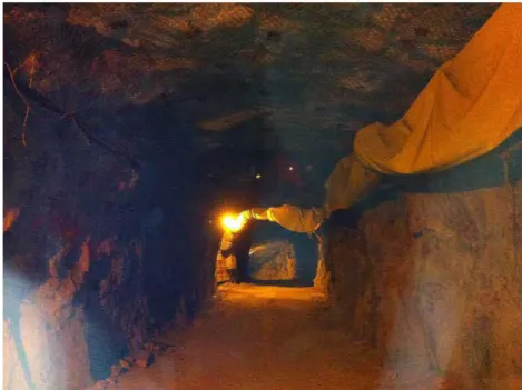
Figure 6- 1. Photography of the mine gallery ... 54
Figure 6- 2. Representation of the WBAN system in a mine environment.. ... 55
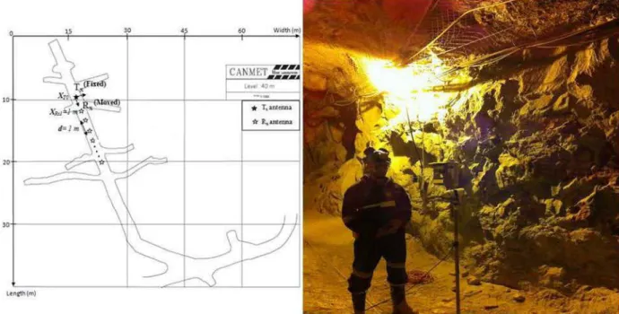
Figure 6- 3. Plan and photo capture of the measurement environment.. ... 56
Figure 6- 4. Antenna positions for the on-body measurements ... 59
Figure 6- 5. On-body measurements test set up in a mine gallery ... 59
Figure 6- 6. Off-body measurement setup ... 60
Figure 6- 7. A photo of the off-body measurement setup ... 61
Figure 6- 8. A picture of the VNA used in on-body and off-body experiments ... 61
Figure 6- 9. Omni-directional and patch antenna used in our project ... 62
Figure 6- 1 O. Measurements output file of extension .TXT ... 63
Figure 7- 1. Impulse responses for the three on-body SISO-M channels ... 66
Figure 7- 2. Impulse responses for the three on-body MIMO-M channels ... 66
Figure 7- 3. SISO capacity CDFs for the three on-body channels ... 69
Figure 7- 4. MlMO capacity CDFs for the three on-body channels ... 69
Figure 7- 5. Impulse responses for the different Tx-Rx separations in the case of SISO-monopole antennas in LOS situation ... 72
Figure 7- 1 O. MMO-M RMS delay spread and coherence bandwidth vs . distance (bad quality) ... 76
Figure 7- 11. MIMO-M and SJSO-M average capacity vs. distance at LOS ... ... ... 76
Figure 7- 12. SISO-M capacity CDFs for the five off-body channel ' distances ... 77
Table 5-1. Typical Measured Values ofRMS Delay Spread [21] ... 50
Table 6- 1. Measurement parameters ... 57
Table 6- 2. Measurements ' equipment for on-body and off-body experiments ... 62
Table 7- 1. Parameters values for each SISO channel ... 68
Table 7-2. Parameters values for each MIMO channel... ... 68
Table 7- 3. SISO capacity values corresponding to typical states of the human body ... 70
Table 7- 4. Values of the different parameters of the off-body channel using monopole antennas ... 78
LOS
NLOS
MIMOSISO
PDP
PL
RF RXTX
SNR
VNA WBAN BANProbability Density Function Channel State Information Decibel (ratio in log scale) Decibel relative to 1 milliwatt Fast Fourier Transform
Inverse Fast Fourier Transform Gigahertz
Root Mean Square
Institute of Electrical and Electronics Engineers Industrial Scientific and Medical
Line-of-Sight Non-Line-Of-Sight
Multiple-Input Multiple-Output Single-Input Single-Output
Power Delay Profile Path Loss
Radio Frequency Receiver
Transmitter
Signal-to-Noise Ratio V ector N etwork Analyzer Wireless Body Area Network Body Area Network
Le Body Area Network (BAN) est une technologie de réseau sans fil qm consiste à interconnecter, autour ou sur le corps humain des transmetteurs et des récepteurs afin d'établir une communication sans fil, impliquant le corps humain. À titre d'exemple, ces composants électroniques utilisant des courants de très faible puissance pourraient communiquer avec un centre de commande distant, pour alerter un service d'urgence. Les applications se trouvent principalement dans les domaines de la santé, militaire, et divertissement.
Cette technologie (BAN) pourrait être appliquée davantage dans un environnement minier en raison de sa simplicité et sa capacité à fournir des informations utiles telles que la surveillance de l'environnement ou d'état de santé des employés. En effet, les mineurs sont exposés quotidiennement à un certain nombre de risques qui affecte leurs santés. Dans le cadre de ce projet, nous proposons un système BAN efficace qui sera à la fois rentable et simple à utiliser dans une mine souterraine.
Ce projet de recherche consiste à déterminer, à la fréquence 2,4 GHz du standard IEEE 802.11, les performances des systèmes de communication SISO (Single Input Single Output) et MIMO (Multiple Input Multiple Output) pour les canaux BAN, en termes de l'étalement des retards (RMS delay spread), l'affaiblissement de parcours, la bande de cohérence et la capacité du canal.
Afin d'atteindre ces objectifs, une campagne de mesure a été effectuée dans une galerie de la mine CANMET (niveau 40m) en ligne de vue directe (LOS) et en ligne de vue indirecte (NLOS) en utilisant les topologies SISO et MIMO.
interconnecting, on or around the human body, transmitters and receivers to establish wireless communication. For example, electronic components, mounted on the human body, using very low power could communicate with a remote control center to alert an emergency service. The BAN applications are mainly found in the areas of health, military, and entertainment.
This technology (BAN) could be applied in a mmmg environment because of its simplicity and its ability to provide useful information such as environmental conditions and employees' health status data. In fact, the miners are exposed daily to a number of risks that affect their health. As part of this project, we propose an efficient BAN system ,dedicated to the security of the min ers, that is both cost effective and easy to use in an underground mine.
This research project consists in determining, at the 2.4 GHz frequency of the IEEE 802.11 standard, the performance of the SISO and MIMO communication systems for BAN channels, in terms of the RMS delay spread, the path loss, the coherence bandwidth and the channel capacity.
In order to achieve these objectives, measurement campaigns were carried out in the CANMET mine gallery (40m level) in line ofsight (LOS) and no line ofsight (NLOS ) using SISO and MIMO topologies.
CHAPITRE 1
GENERAL INTRODUCTION
1.1) Introduction to the Master Project
Wireless communications have undergone tremendous growth. They were first used mainly by military and shipping companies and later quickly expanded into commercial use such as commercial broadcasting services (shortwave, AM and FM radio, terrestrial T V), cellular telephony, global positioning service (GPS), wireless local area network (WLAN), and wireless personal area network (WP AN) technologies. Today, the se w ireless communications systems have become an integral part of daily life and continue to evolve in providing better quality and user experience. One of the recent emerging wireless technologies is body area network (BAN).
Over the past years, this technology increasingly attracted a great deal of interest from academia, industry, and standardization bodies, because of the advances in process technologies and low cost integration solutions which opened the door to various applications of the (BAN) technology. In very broad terms, WBAN refers to the w ireless communication technology encompassing the propagation at the on-body, off-body, and in-body channels. In
the on-body channel, both the transmitter and the receiver are on the human body surface, whereas in the in-body channel the transmitter is within the body. In the off-body channel, the transmitter is located on the body, whilst the receiver is in the vicinity of the body. This growing technology has found many applications in the biomedical therapy, health care, sport, multimedia and entertainment, to use the body as a communication media or transmit the human vital signs [ 1].
There are many physical and environmental phenomena which affect the BAN signal propagation. The movement of the body parts, polarization mismatch, and scattering due to the body, will cause fading of the signal. Shadowing of the links and reflect ions from the
Additionally, the surrounding environment will cause fading, such as fading due to the floor or ground, and fading due to local environment, such as fumiture, walls of a room, machinery in a mine gallery ... etc.
In addition to fading, another very important concem for on-body communication is the transmitted power, which is to be kept as low as possible. 0 dBm is still believed to be a high transmit power for the body area networks. Reducing power level allows increasing the battery life and reducing the Specifie Absorption Rate (SAR) value, which is highly desirable [2].
Applications of the BAN technology is increasingly finding grounds in personal healthcare, entertainment, security and personal identification, fashion, and personalized communications, which drives research to establish more reliable and efficient link between the deviees mounted on the body. The current standards for wireless communications like Bluetooth [2, 3], Zigbee [2, 4], and BodyLAN [2, 5] are already operating but there is still much room for improvement.
Moreover, multiple antennas for the on-body and off-body channels is an optimal solution for providing high data rate and reliable transmission bet ween the body-wom wireless deviees and sensors, such as in military applications, sports and entertainment, and patient monitoring systems.
In fact, for optimal communication, it is necessary to minimize fading and increase the output signal to noise ratio (SNR) without increasing the transmit power, which is an advantage of using MIMO systems. In these systems, antenna diversity, also known as space diversity, is a well-known solution toward overcoming fading and providing a power efficient link in mobile communications, and hence improving the quality and reliability of a wireless link. The channel capacity can be significantly increased through the use of multiple-input multiple-output (MIMO) techniques which are useful for high data rate applications. The use of MIMO techniques for on-body communications has received little attention, as much of the work on body-centric communication focuses on the antenna design [2,6], channel characterization [2, 7, 8], and the effect of human body presence on the link performance. Sorne preliminary measurements are reported with two monopole antennas at the receiver end
for on-body channels in [2, 9, and 1 0]. Additionally, first and second order statistics and sorne diversity results for channels with wearable receiving antennas where the transmitter is at a fixed position in the room are presented in [11, 12], thus characterizing the off-body channels and sorne on-body channels as well.
Moreover, many researches have been carried out to investigate the performance of the off-body channels at the 2.45 GHz ISM (industrial, scientific and medical) band, in the past few years, benefitting from the development of deviees miniaturization technology [13]. Various other articles in the literature deal with on body communication systems, for patients' vital signs monitoring application [ 13].
In general, much of the works on WBAN multiple-input multiple-output (MIMO) systems concems the characterization ofMIMO on-body channels, while the MIMO off-body channel characterization was somewhat neglected [14, 15]. This may have been due to the fact that ensuring a communication in off-body channels may be challenging because of the short range nature of the used deviees.
On the other hand, there has been a growing interest in implementing MIMO systems in indoor environments, because of their now proven efficiency in offering high data rate and low error rate communications [8, 16-18]. In fact, while MIMO systems have been extensively investigated for applications in tunnel roads and subways in the last few decades, the study ofsuch systems in underground mines is stilllimited [16]. Benmabrouk et Al. have thoroughly investigated the use of MIMO systems in a mine gallery in the 2.45 GHz ISM band, for conventional radio transmission, using different kinds of antennas, namely the monopole and the patch antennas [19]. Interesting results were driven to show the capacity improvement relative to SISO case due to the exploitation of MIMO capabilities in both line of sight (LOS) and no line of sight (NLOS) applications. Even more, the effect of the mining machinery was taken into consideration in [19].
This Master report is concemed with the on-body and off-body communication inside a mine gallery where the transmitter is wom by the mine worker, whereas the receiver is either on the body or at a close proximity from the body.
Analyzing the performance of MIMO system in the mining environment which includes a lot of scattering objects, reflecting metals and shadowing structures, affecting both the path gain and the time dispersion of the link, is not an easy task because of the so-mentioned
more challenging. To the best of the authors' knowledge, no study of the MIMO neither on-body nor off-on-body channel characterization in a mining environment was reported yet in the literature.
Therefore, in this thesis report, the characterization and capacity evaluation of the 2 x2 MIMO and SISO off-body channels are investigated in underground environment at the 2.45 GHz band. The effect of directivity is sought by using monopole and patch antennas for both LOS and NLOS situations. First, the channel impulse responses are evaluated for different locations of the access points relative to the body. The path loss is then determined and plotted for different distances between the transmitter and the receiver and the path loss exponent is derived. Moreover, the channel capacity is calculated from the measurements similarly to [20] and [21]. The capacity study in both scenarios aims at showing the effect on the MIMO link capacity of a strong LOS component and multipath propagation. Moreover, the relationship between the average capacity and the average SNR is also highlighted. The coherence bandwidth and RMS delay spread are also derived and discussed.
In the on-body section of the report, the performance of SISO and MIMO WBAN systems, in a mine gallery, is comparatively evaluated at the 2.45 GHz ISM band. Three on-body channels (Belt-Head, Belt-Chest, and Belt-Wrist) were characterized with the on-body at different postures. The channel capacity was derived from the measurements similarly to [20] and [14], and then compared for the three on-body channels. TheRMS delay spread, and the coherence bandwidth were also derived (similarly to [21]) and compared for different measurement scenarios.
1.2)
Pro blemRecently, there has been a great deal of focus in establishing communication on or around the body. In body-centric communications, communication is established through nodes which are placed on the body, or close to it, communicating with each other or with other nodes positioned apart from the body such as base stations or central data storage deviees. Wired connection of the nodes is inconvenient because it can obstruct the free motion. The use of special fabrics, would allow the user to move comfortably, but it may not
be desirable to wear due to fashion preferences of the user. Other proposed methods in elude body current mechanism and near field communication. Body current method uses the emission of electric field on the surface of the body to use it as a transmission path [2]. Near-Field communication uses magnetic field induction for very short-range communication [2]. None ofthese two techniques is suitable for high data rate applications (like video streaming and multimedia). Wireless connectivity with antennas is therefore a very suitable choice.
Among the major issues that should be considered in body area communications are the antenna design and performance, channel characterization, the effect of human body presence and movement, and the transmitted power. A wearable antenna should be low profile, light weight and comfortable for the body surface [22]. The wearable RF components should also be able to support a high data rate transmission and should have low power consumption. Therefore, the use of a high enough frequency and a highly efficient link is required [2]. Moreover, for effective design and understanding of the channels, the knowledge of electromagnetic properties of the human body is essential.
In addition to the previously mentioned problems, wireless communication systems in an underground environment should be designed to provide reliable services w ith high throughput. However, the conventional communication systems, using a single antenna for transmission and reception SISO have a capacity limited by the transmission power and the bandwidth of the radio link [23]. Additionally, communication systems centered on the human body are limited in transmission power [24]. Therefore, radio systems that are centered on the human body can benefit from the application of MIMO architecture to improve capacity [14]. Moreover, it is well known that the performance of MIMO system s depends on the conditions of the radio channel, which differs from one m edium t o another; this justifies the need to study the on-body and off-body channels in a mine, highlighting the impact on the capacity due to the use of MIMO systems. For a complet e characterization of these channels, several channel parameters should be determined (such as : RM S delay spread, coherence bandwidth, path loss exponent, and fading).
1.3) Objective of the research project
In this master's project, the multiple-input multiple-output (MIMO) off-b ody and on-body channel capacity is investigated in the underground mine untypical indoor environment
antenna directivity on the capacity of such channels. Furthermore for the off-bod y scenario, both line of sight (LOS) and no line of sight (NLOS) scenarios are of interest and the off-body channel is characterized in terms ofthe channel impulse response, path-loss, RMS delay spread, and coherence bandwidth. In On-body experiments, three On-body channels were characterized in terms of the channel impulse response, RMS delay spread, coherence bandwidth; the channel capacity was also determined. The variation of these parameters in the different measurement scenarios was also discussed.
1.4) Research methodology
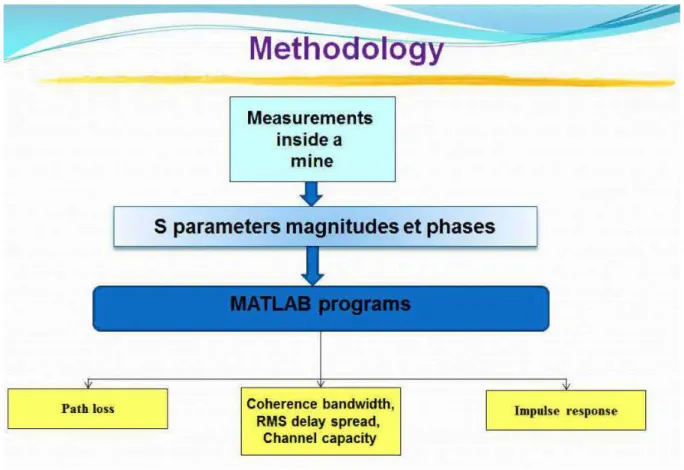
To meet the BAN communication system requirements m an underground mmmg environment, we used the following methodology:
• In the first phase, we conducted a state of the art by focusing m ainly on the characterization ofthe on-body and off-body channels in indoor environments and on the use of MIMO topology in mining media to improve the capacity of the propagation channel.
• In the second phase, a measurements campaign was conducted in the CANMET gold mine near Val d'Or in Canada as shown in figure 1-1 and figure 1-2. The environment mainly consists of very rough and dusty walls, floor, and ceiling. The temperature is about 6° C in a highly humid environment. There is mining m achinery few m eters away from the measurements ' setup; the ceiling includes many m et al rods and is covered with metal screens. In order to characterize the off-b ody SISO and MIMO channels propagation in this mine gallery at the 2.45 GHz band, the transmitting antennas were placed at a fixed position in the middle of the mine pathway ( 40m underground). The receiving antennas were placed on the right side of the chest of a 1.80m, 75Kg male subject wearing a miner's outfit. Two t ypes of MIMO antennas were used during the measurements, namely a 2x2 MIMO m onopole antenna set and a 2x2 MIMO patch antenna set; therefore the impact of antenna directivity was addressed. Both the transmitting and the receiving antenna elements are separated by a half wavelength distance, thus approximately 6 cm. During the measurements, 6
data snapshots were collected at each distance, from a distance of lm through Sm away from the transmitter, as shown in figure 1-2. The transmitting and receiving antennas were connected to the two ports of the previously calibrated vector network analyzer (VNA). At each snapshot, the 521 values were recorded for 6401 frequency samples around the center frequency of 2.45 GHz. The noise floor for the measurements was considered at -90 dBm. In the body measurements, three on-body channels were considered for the measurements. For each on-on-body channel, the transmitting antenna set (TX) was placed at the left side position of the belt. The receiving antenna set (RX) was placed altematively at the right side of the ch est (RX 1 ), the right si de of the head (RX 2), and at the right wrist position (RX 3), thus forming three on-body channels: belt-chest, belt-wrist, and belt- head as shown in figure 1-2. The transmitting antenna set was placed to point upward, and the receiving antenna set was pointing downward. The distance between the body and the antenna was kept at about 5-l 0 mm. The transmitting and receiving antennas were connected to the two ports of the vector network analyzer (VNA), after calibrating the VNA with the cables connected to it. Figure 1-2 shows the human test subject and antenna connections in the mine environment.
• Finally, after getting the S-parameters, using simulation software MATLAB, we have determined the parameters of the channel such as: the path loss, the coherence bandwidth, theRMS delay spread, and the capacity ofthe channel.
Measurements inside a
mine
5 parameters magnitudes et phases
Coherence bandwidth, RMS delay spread,
Channel capacity
Figure 1-1. Research methodology black diagram
---TX <;>E
~
f-1m ~ 2m""
4m SmFigure 1- 2. Measurement setup
1.5) Thesis structure
In this thesis report, we present the following tapies:
Impulse response
Chapter 2 provides an introduction to body area network. It briefly reports the applications of this technology and the different phenomena affecting the propagation at this channel. The different types of WBAN technology are summarized.
Chapter 3 provides an overview of the MIMO systems. It theoretically describes the MIMO channels through the channel matrix, and talks about the MIMO capacity.
Chapter 4 comparatively discusses the different types of diversity. It defines the diversity gain parameter as a mean to quantify the benefits of the different diversity techniques .
Chapter 5 gives an overview of the channel characterization types and the param et ers that are usually used to characterize the propagation channels. It t alks in detail about the fading as the main issue affecting the electromagnetic signal propagation. Finally, the chapter briefly introduces the different types of channel modelling.
Chapter 6 details the research methodology. This includes a description of the environment, measurement equipment and measurement methods. Mounting antennas on the body, to constitute various on-body channels, is discussed and the details ofthe measurement setup for the on-body and off-body experiments are given. The movements performed during the measurements are also described.
Chapter 7 discusses the different results obtained for the on-body and off-body sets of measurements inside the CANMET mine. It combines the results from the different measurement scenarios to determine and discuss the different channel param et ers including the channel impulse response, path-loss, RMS delay spread, and coherence bandw idth.
Chapter 8 summarizes the derived conclusions and opens the door for Future Work possibilities.
1.6) Conclusion
This chapter consisted of an introduction to the master project, which atms to characterize the SISO and MIMO channels inside a mine gallery. It presented the problem s associated with a WBAN communication system inside a mine and briefly mentions the techniques used to combat these problems. The objectives of the research project have been detailed, and the methodology followed to achieve them is described. In subsequent chapters, sorne back ground information related to the different them es of the mast er project 1s presented, starting by an overview of the WBAN t echnology in chapter 2.
CHAPTER2
OVERVIEW OF THE BODY AREA NETWORK
2.1) Wireless body area network (WBAN) technology overview
Body-centric communication is established through nodes which are placed on the body, or close to it, communicating with each other or with other nodes (such as base st ations or central data storage deviees) positioned at a close proximity from the body.
2.1.1) On-body technology
The on-body technology 1s a kind of body area network (BAN) communication technology that found many applications in personal health care, entertainment, military, firefighting and many other fields [25].
In the on-body channels, both the transmitter and recetver move and change their position in the scattering environment and with respect to each other. Perhaps the most significant phenomenon affecting the on-body communication is channel fading, which occurs during normal activity, due to the dynamic nature of the human body, the multipath around the body, and the scattering by the environment. This fading can be mitigated through the use of diversity.
On-body communication applications are linked to several fields, such as medical-sensor networks, emergency-service workers, and entertainment. This technology also received a great deal of interest from the defense department, in order to wirelessly connect on-body soldier equipment. The medical field exhibits different uses for the on-body technology such as: Medical implants, patient monitoring and diagnostic systems, and personal health care. Sorne published reports demonstrated the strong interest of the defense field in the on-body technology, in terms of interconnecting various subsystems on a soldier [26]; It was found
that the Line of sight (LOS) was established reliably (most of the scattering is directed away from the body). Moreover, high path loss attenuation was observed in a link through the torso due to the human shadowing [26].
Other application areas for the on-body technology include: security, police, sports training, fire fighters, personal identification, fashion, and personalized communications as seen in figure 2-1.
Figure 2- 1. Sorne on-body applications [24, 26].
2.1.2) Off-body technology
The off-body technology deals with the communication link between deviees mounted on the body, and other deviees, or access points, away from the body. It found application in the industrial and medical fields. Examples of this technology include wearable RFID tags, and body -wom sensors to and from the data acquisition system or server, for a medical support network with wireless sensors placed on the body; figure 2-2 represents sorne of the off-body applications. Careful attention should be taken in antenna design, placement, and orientation. The antennas should have radiation patterns directed away from the body, providing aU-round coverage and must be isolated from the body to avoid the effect of human body on the antenna performance [2]. Indeed, the most important factor that affects the quality of propagation in the off-body technology is the shadowing effect, which causes fading. This is due to the pedestrian movement that obstructs the off-body radio link and results on multi-path disturbance. It was found that using multiple antenna techniques reduces the influence of pedestrian effects on off-body radio-links [27].
Figure 2- 2. Sorne off-body applications [2, 57].
2.1.3) On/Off-body technology
On/Off-body communication is another technology that is of interest to many fields including health care and military. This communication's link combines the characteristics and challenges of the on-body as weil as the off-body link. For example, this link will require antennas that can support the two technologies (on-body and off-body communication). This is very challenging because the on-body link requires a polarization pattem that is parallel to the body surface, while the off-body link requires one that is directed away from the surface. The challenge is further aggravated when moving toward microwave frequencies where the path loss is greater and antenna design and orientation should be carefully taken care of [2]. A possible solution is to design a configurable antenna that can work either in the on-body mode or the off-body mode by using microwave switches embedded in the deviee. This idea was cleverly applied in [27] with a design of an apetture coup led microstrip patch antenna that is fed using stripline. The antenna changes its functionality from the on-body mode to the off-body mode using switches and is able to attain a retum loss that remains below -30 dB
throughout the entire operating frequency with a linear increase of the path loss from -0.39 dB at 1 GHz to -1.65 dB at 4 GHz.
2.1.4) In-body technology
The in-body technology consists of one or more TX-RX link through the human body. Benefitting from the new microelectronic technological achievements, it found interesting applications in the medical field where implantable medical deviees, communicating w ith the outside world, are put inside the human body. Examples of these deviees include the heart pacemakers and retinal implants [2].
2.2) WBAN technology normalization
Efforts have been made to develop standards for the WBAN and an IEEE t ask group, IEEE 802.15.6 (IEEE 802.15.BAN), has been established for this purpose in November 2007. This task group is the sixth task group of the IEEE 802.15 working group.
IEEE 802.15 is a working group of the Institute of Electrical and Electronics Engineers (IEEE) 802 standards committee which specifies Wireless Personal Area Network (WPAN) standards [2]. It includes seven task groups and one interest group for Terahertz called IGTHz. In December 2011, the task group 802.1 5.6 or 802.1 5.BAN and t ask group 802.15.7 developed new standards for BAN and Visible Light Communication (VLC), respectively. IEEE 802.15.1, first published in June 2002, is a st andard for WP AN based on Bluetooth, whereas, 802.15.2 pro vides recommendations for the coexistence of the WP ANs and Wireless Local Area Networks (WLAN) [2]. More details about other task groups of IEEE 802.15 are given on its website.
2.3) Antennas for WBAN channels
The 2.45GHz channel allows the use of smaller antennas, because the wavelength for this channel is in the range of few centimeters (about 12 cm). This advantage in the dimension cornes with complexity of the design for a WBAN channel. The requirements for antenna design at 2.45 GHz for WBAN applications could be summarized as follows .
characterizes the WBAN channels, but not too high to be harmful. In fact, sorne antenna characteristics (such as the radiation patterns and gain) may change drastically in the presence of a high loss medium such as the human body [2].
In order to maximize coupling between body-worn deviees, the max1mum of the radiation pattern should be tangential to the body's surface ( creeping waves propagation) [22]. However, in this case, the wave polarized parallel to the body will attenuate faster than the perpendicular polarized one [2]. For off-body communication, the pattern must be directed away from the body. Omni-directional radiation pattern antennas (such as the monopole antenna) placed tangential to the surface of the body are generally considered suitable for on-body applications, when taking in consideration the gain reduction due to the presence of the body [2]. For on-body applications, where the wave propagates along the surface of the body as creeping wave and is attenuated much more rapidly compared to the free space [2], the antenna must be designed for a minimum SAR. This could be achieved by by the use of a suitable ground plane of the antennas to re duce back radiation [2]. Careful attention should be clone during the design to insure a low reflection coefficient at the desired frequency even when the antenna is mounted on the body, taking in consideration that detuning could occur in the presence of the human body [2].
Comparative studies of various antennas (such as the rectangular patch, monopole, PIF A, and circularly polarized patch antenna) were performed and the antennas parameters were compared in [ 29, 30]. According to those studies, sorne antennas can perform well in sorne aspects, and perform badly in other aspects. The monopole antennas, beside their disadvantageous shape, exhibit the best path gains. The patch antennas have the advantage of their low profile shape and are more stable in terms of mismatch, but do not provide a satisfactory link performance. The textile wearable antennas are the best in terms of weigh and shape, they are flexible and could have comparable performance to conventional printed antennas [2].
2.4) Human body modeling and phantoms
Developing BAN systems in the GHz range may benefit from the development of experimental phantoms emulating the dielectric propetties of human skin in order to accurately characterize the on-body propagation channel; this requires an accurate estimation of the absorption of the electromagnetic power by the human body.
It is impmtant to know that the dielecttic properties of the human body are frequency dependent. Moreover, the penetration depth ofthe lower frequencies is higherthan that ofthe higher frequencies [2]. The penetration depth and conductivity for muscle and fat tissues are shown in figure 2-3.
As it's seen from figure 2-3, the peneu·ation depth at 2.45 GHz is much smaller compared to low frequencies; hence, at this frequency, the propagation will lik.ely be confined to the surface of the body, especially at small transmitted powers.
'ê è 10,, - - - , - - - , . . - - - , - - - , - - - - , 101
... _
...
....
______ _
1o• ~~~~~~~~,o.~~~,o~' ~~u_~= Frt(Juon<y (MHZ) (a) ~~ ----r--~~~--,--~f
Jo'L
-~
1 /""
/__
... -101____
.,_...,,
1~ 101 fr«JUOII<Y tMHt) i'h\ / /Jo'
Jo'...
& t 100 ......
_
... ...'
'
'
.. 10 .§'
'
'
j
... ·.~~~~~ ••• ~~~.~~~~,L.~ ~~,~ •• ~~~, •• kcqwncy(M:Hl) (<)Figure 2- 3. Electromagnetic propetties of Muscle (solid line) and Fat ( dotted line) tissues
with respect to frequency (a) Relative Permittivity (b) Conductivity and ( c) Penetration depth [2].
literature, namely, the liquid, semisolid, and solid phantom [2]. The three types differ upon complexity, frequency usage, and durability.
Firstly, liquid phantoms are homogenous phantoms that representa convenient way to simulate the body. They are well suited for measurements in the 30-MHz-6-GHz range but cannot be used at millimeter range be cause of the Shell [31]. Semisolid phantoms do not require any bounding container and have been used for antenna and on-body channel characterization [31 ]; They are especially useful to simulate organs with high water content like muscle and brain etc [2]. Finally, solid or dry phantoms have the advantage of keeping the ir shape for a long period of time and have stable characteristics. The se phantoms can be built from a single organ phantom to whole body phantoms, depending upon the application.
2.5)
Conclusion
In this chapter, WBAN technology has been explained. Four types of system s were discussed, namely the on-body, off-body, on/off-body, and in-body technologies. The particularity of the WBAN systems, which enforces different restrictions on the antenna design, was discussed. Finally, different types of phantoms emulating the dielectric properties of human skin were presented comparatively. Sorne other concepts mentioned in the introduction shaH be the subject of further clarification throughout this manuscript, including the MIMO systems which are explained in the next chapter.
CHAPTER3
OVERVIEW OF MIMO SYSTEMS
3.1) MIMO channel
The limitations of SISO systems ( containing a single transmit antenna and a single antenna at the reception), due to the richness of multipath in a confined space such as a mine, have led researchers to consider alternative solutions in order to improve the capacity of the wireless systems. Renee, several studies have concluded that a system with multiple antennas at the transmission and at the reception takes advantage of the multipath to considerably improve the capacity ofthe radio link compared to a SISO system [32].
In fact, MIMO techniques are known to significantly improve the r eliability of w ireless systems by lowering the bit error rate (BER), improving the signal t o noise ratio, and enhancing the capacity of the system. This could be achieved through diversity which proved to be powerful in lowering fading and improving the BER [2, 24, 33]. Diversity provides the best results when the fading at the different branches is uncorrelated and the branch signais have the same average power [33]. Usually, the higher order MIMO schemes are able to achieve the best performance in terms of BER. It was shown that a 4 x4 MIMO usmg space time codes, provide a better BER performance than a 2x2 or a 1 x 1 MIMO [24].
MIMO technology allows increasing the capacity of the w ireless system w ithout an increase in bandwidth. This increase in capacity is limited by the correlation and power imbalance among the spatial sub-channels, mutual coupling between the spatially separated antennas, and the presence of a strong direct link between the transmitter (Tx) and receiver (Rx) in the line-of-sight (LOS) transmission [34]. In an interesting on-body research, using two different models ofthree MIMO on-body channels each (using PIFA antennas), ergodic capacity performance has been examined in [35]. Results show that the belt head channel is comparable to a Rayleigh distribution, while the belt-chest exhibits a loss in MIMO capacity because of the presence of a strong LOS component [35].
on-body application used by fire fighters [24].
1
o·
3 , - - - , - Small person ·-·- Medium ·-·- Medium person-2 --- Large
10 1u0 --~2~0 _____ 3L0~~~40~~=5=0==~~60 10-4 ~ ,L·=--=L=a~rg~e~p=e=rs=on==~L_ ____ _ L _ _ ~~ Eb/N0 [dB]
-10 -5 0 5 10
Eb/N0 per input antenna [dB]
Figure 3-1. Improvement in terms ofBER and SNR for MIMO systems with respect to
SISO systems for on-body application used by fire fighters using three different body s1zes [24]
In general, it is demonstrated that MIMO systems (shown in figure 3-2) have the ability to turn multipath propagation, traditionally a disadvantage of wireless transmissions in a benefit to the user. They benefit from the random fading [36, 37], and the multipath [38, 39], for the purpose of expanding the transfer rates.
Dl
·---·
'"-...
...:\ ,--
,,
' \,-
w~' .,.---~,
, ' ~--~- ,.::-,. , ' - ,. - "'9-..., , - ~<"" - , 1.1'1... ... - ... ,! - ~~ .,..,. '\ ~,
,_
, _ - - - - " " ' - - - -'
.... -~--, - - Jop,
:r;l hll [::: y ,Dl [;.. ~ 1 '..
' , , ", ~:\ " ' ._, ' A,
, ' , ' ....,
,
... \, , , , ... ,< , ot' ",
..
.... '\,
, .... " ~,
....
~"
,
, ' ' '\ , , .... ....,
.,. ...."
,,,''
x.T ,:, hR.T .. ~ ~ ·---~•
•
•
•
•
•
DR. D...
...
Tx
Rx3.2) MIMO matrix
The MIMO input-output relationship between rn transmit and n rece1ve antennas 1s described by the following equation [14]:
Y=HX+N (3-1)
where X is the [rn x 1] transmitted vector, Y is the [ n x 1] received vector, N is the receive additive white Gaussian noise (AWGN) vector, and H is the n x rn channel matrix which for the case of the 2x2 MIMO considered channel is reduced to
H=[hu h12]
hzt hzz (3-2)
where hii is the complex random variable that represents the complex sub-channel gain from the ith transmitting antenna to the jth receiving antenna. In our measurements, the values of the parameters S21 correspond to the different hii values.
3.3) Correlation of the bran ch signais
The correlation of the branch signais greatly affects the performance of a MIMO rece1ver. When the correlation is low, the branch signais fade differently, allowing an increase in the ergodic capacity at the receiver [2]. For most of the mobile communication scenarios, correlation coefficient of0.7 is considered suitable [33]. One useful measure ofthe branch correlation is the complex signal correlation coefficient ps, wich contains both the phase and amplitude correlation.
(3-3)
Where V1 and V2 represent the zero-meaned complex voltage signais of port 1 and 2,
bandwidth that can be reliably transmitted through a certain channel [ 41].
In this thesis report, the MIMO channel capacity is used to measure the performance of the MIMO link taking in consideration the effect of the SNR and the multipath richness.
Channel ergodic capacity for a regular SISO configuration is calculated using the well-known Shannon formula [20]:
C5r50[bpsjHz] = log2(1
+ piHI
2). (3-4)Where His the normalized channel response and p is the average signal to noise ratio (SNR).
Similarly, the channel capacity with MIMO configuration is computed using the following formula [14]:
CMrMo[bpsjHz] = log2(det[In
+
SNR av HH*]) (3-5)m
Where His the normalized m x n channel response (rn 2:: n), SN Ra v is the average signal to noise ratio, ln is the n x n identity matrix, and
*
represents the complex conjugate transpose . In our case, H matrix is normalized such that at each realization, the square of its Frobenius norm is equal to the product ofits dimensions CIIHII~ = nm) [42, 43].The Frobenius normalization method allows investigating the multipath richness of the environment [14]. The outage capacity, which is calculated from the CDF curves at a certain probability, ideally follows a Rayleigh distribution of the envelopes when subchannels of the MIMO system are independent and identically distributed (iid) and hence perfectly uncorrelated. This is however not true for practical systems, especially in the presence of a strong LOS component [ 14, 19].
3.5)
Conclusion
In this chapter, the theoretical study of a MIMO communication system is presented. Then, the capacity formula for a SISO and a MIMO configuration was explained. Thus, MIMO systems seem very beneficiai for wireless communications, since the maximum theoretical bit rate increases with the number of antennas used, without any increase of the transmitted power, or the bandwidth of the signal. Therefore, it is now clear that our solution which consists of implementing and studying a MIMO WBAN system in underground mines, is clearly justified. While, we only used space diversity in this project, we are presenting the different kinds of diversity schemes, in the next chapter, to get the reader to understand this concept and appreciate its implementation m our project.
CHAPTER4
DIVERSITY OVERVIEW
Diversity refers to a method for improving the reliability of a communication system by using multiple communication channels to send or receive information [2]. Diversity is a well-known technique in combatting fading and co-channel interference and improving the bit error rate [2, 24, 33]. Diversity techniques benefit from the fact that different channels experience different levels of fading and interference to improve the gain and capacity of the system. The multipath richness is exploited to improve the diversity gain. The general idea is to use multiple uncorrelated branches with statistically independent fading characteristics. When the different channels are sufficiently separated in time, frequency, space, radiation pattern, and 1 or polarization, the fading on the individual channels will be independent due to the different channel conditions; hence, with proper combining ofthe branches, the SNR can be improved due to the deep fades reduction [2]. Figure 4-1 depicts an example of diversity at the reception.
Diversity Branches
~
Tx
N4.1) Types of diversity
Diversity can be applied in several ways:
• Antenna diversity or space diversity, is a type of diversity that uses two or more antennas at the transmission or/ and at the reception to improve the wireless link quality and reliability, by exploiting the multipath richness of the environment. It is mainly effective in urban and indoor environments where there is rarely a clear line-of-sight (LOS) [2]. The multipath components usually exhibits phase shifts, time delays, attenuations, and distortions and can destructively interfere with one another at a receiver. Space diversity, because of its inherent multi-view of the received signal, is effective at mitigating these multipath issues. In fact, the signal will fade differently at each antenna. Thus if one antenna experience a deep fade, it is unlikely that the other antennas will behave in the same manner. Hence the overall performance of the link is improved [2].
• Time Diversity consists of sending the same amplitude samples at different time slots. When the time slots separation is high enough (at least the reciprocal of the fading bandwidth), the sequential amplitude samples ofthe fading signal will be uncorrelated [2].
• Frequency Diversity consists of transmitting the signal over several frequenc y channels with a separation that is necessarily greater than the coherence bandwidth [2].
• Pattern Diversity consists ofusing directional antennas at either at the transmitter or at the receiver (such as a bearn switching array). The radiation patterns are directed in different angles undergoing different fading, and hence uncorrelated; ideally the different patterns should have a minimum overlap and a combination of patterns similar to an Omni-directional pattern [2].
• Polarization diversity consists of transmitting and receiving multiple verswns of a signal through antennas having different polarizations. A difference between the polarized components received at the receiver usually called the cross-polarization discrimination (XPD), must be low for effective polarization diversity to get a high diversity gain [2].
presented in [ 44]. This investigation showed that using spatial, polarization, or pattern diversity, diversity gains of 7-10 dB are achievable at the 99% probability level. Diversity gain of 8 to 9 dB is typical in NLOS indoor and outdoor channels using antenna spacings as small as 0.1--0.15/.. [44]. The same research indicates that polarization diversity configurations can increase SNR by 12 dB or more in certain cases by eliminating polarization mismatch. In general, space diversity performs better than other types of diversities when the incoming angles of arrivai are uniform such as in the open surface communications. Space or pattern diversity outperform the polarization diversity in a situation where the transmitted wave is not heavily depolarized (such as the LOS situations) due to a high XPD [2]. In NLOS scenario the performance of the polarization diversity is comparable to that of a space diversity [2]. Polarization diversity has the advantage over space diversity in terms of economizing the cost because it can be designed using a single multi-polarization antenna, contrary to the space diversity [2].
4.3) Diversity gain
One parameter which measures the improvements in the signal strength, SNR, or BER due to the use of diversity is diversity gain. It provides a good incite on the improvem ent in the communication quality due to diversity. Diversity gain is m easured at a certain outage probability (usually 1% or 10% probability level), by comparing the values of the signal strength, for example, of the diversity combined signal with that of the strongest branch signal as seen in figure 4-2 [2].
~ Branch 1
..
f-,
/ f- .... " /,
r- - - Branch 2 ...--...ro
(/) (/) '(3 (/) ..0ro
v <1>>
<1>ro
c
0'>ü5
"-" o._ f-/ /
r- -·- ·- ·- Diversity Combined signal
,--
,
..
/
/
1 10 -1 10 -2 -3 10 -90 ~/ /
,
·',
,
..
I i ~, / i ;/
.',
,
/
,:,
DG ...i
r'1.
,;,
,
f.
.#,
.
,
J.
,...,# ( ' 1,
1
1,,
1,
:
-80 -70 -60Powe r Leve l (dB)
Figure 4- 2. Diversity gain calculation [2]
l
;
Diversity gain is defined as follows:
DG= Pdiv Pref DG= PdBdiv - pd Bref (dB) (4-1) (4-2) .~
J
-50..
where Pd iv , Pref, PdBdiv , and Pd Bref are respectively the power lev el of the diversity combined signal, the power level of the reference signal (which is strongest among the branch signais) and those same parameters expressed in dBs at a certain probability level. Diversity gain can also be presented in terms of SNR or BER and is inversely dependent upon the correlation and the power difference among the branch signais [44, 45, 46]. Results from experimental investigations and comparison of antenna diversity techniques for on-body and off-body radio propagation channels show that for rich multipath environment the diversity gain is higher for the non-line of sight cases compared to the line-of-sight scenarios; it was also observed that off-body diversity is almost 50% more efficient than on-body diversity (50% more DG for the off-body) [47].
In this chapter, we presented an overvtew of diversity which is used to improve the performance and overcome fading. This requires a sufficient separation of the different channels intime, frequency, space, radiation pattern, and 1 or polarization, in order to achieve deep fades reduction and an overa11 improvement in SNR. Different t ypes of diversity have been compared, and the diversity gain parameter has been introduced as a mean to measure the improvements in the signal strength. While the previous sections talked about the WBAN systems and the importance of diversity for a good WBAN communication, the next section will talk about the core concept ofthis project, which is the channel characterization.
CHAPTERS
CHANNEL CHARACTERIZATION OVERVIEW
When an electromagnetic wave propagates through a radio channel, it is affected by diverse phenomenon, affecting its quality and sometimes severely harming the communication link. These propagation issues are generally attributed t o reflection, diffraction, and scattering, which will be discussed in the follow ing sections. In indoor environments as it is the case for a mine gallery, the direct line of sight path is sometimes obstructed by the different objects and natural obstacle potentially causing a severe diffraction loss. As a result, multiple reflections occur allowing a multitude of paths of different lengths, between the transmitter and the receiver. At the receiver, the beams arriving through the different paths will interact causing multipath fading at a specifie location, and the signal strength will decrease with distance. Different propagation models are available to predict the wave propagation. Large scale propagation models predict the mean signal strength as a function of the Tx-Rx separation. On the other hand, small scale propagation models predict the rapid fluctuations in the received signal over short distances (a fe w wavelengths). The free space propagation model predicts the signal strength at line of sight situations, where the Tx-Rx link is not obstructed. The well-known Friis formula categorizes this received signal as follow:
Pr _ Gt.Gr( À )2
-
-Pt L 4nd (5-1 )
Where Pr, Pt, Gr, Gt are respectively the received power at a distance d, the transmitted power, the receiver antenna gain, and the transmitter antenna gain. À is the w avelength, d is the Tx-Rx separation, and Lis the system loss (L~ 1).
The channel characterization is a process that studies the channel properties of a communication link. It is a study of the signal propagation from the transmitter t o the receiver which represents the combined effect of different phenomena such as, scattering, fading, and
This knowledge of the transmission channel in an underground mining environment is essential for the design of transmission systems that meets the need of miners. Follow ing recent underground mining accidents, the development of a system dedicated to miner safety communications has become a primary need.
The characterization of the propagation channel consists in determining the parameters of the channel in order to understand the propagation mechanism or build a propagation model describing the behavior of the channel.
5.1) Large-scale channel characterization
Large-scale channel characterization consists of path loss (PL) and shadowing effect. Path loss is defined as the ratio of the received signal power to the transmit signal power [21]. In addition to free-space loss, the WBAN channel endures additional losses due to the shadowing obstacles, oxygen absorption, and rain attenuation. This poses a severe challenge in delivering a gigabit wireless transmission with reliable link margin.
Shadowing signifies the average signal power received over a large area (a few tens of wavelengths) due to the dynamic evolution of propagation paths, whereby new paths arise and old paths disappear [21]. V arious measurement results reported in the literature have shown that the shadowing fading is log-normally distributed [ 48, 49]. Figure 5-1 presents a typical example of signal propagation in an indoor environment highlighting the types of fading [57]. Figure 5-2 shows the oxygen absorption and rain attenuation vs frequency.
18 17.5 17
E'
ID ~ 16.5 (Ds
0 16 a.. "0 (]) > (i) u 15.5 (]) a:: 15/'
small-scale fading 14.5 14 2.5 3 3.5 4 4.5 Transmitter-Receiver Separation [m]Figure 5- 1. Ex ample of signal propagation in an indoor environment highlighting the types
offading [57]. 102 101 Ê 10°
ci5
~·
~
=
l
/
~ l5 Hrl ..s 'l\.1
i,..-,... \..
f1
~ :::1 c: 1!' 1 1 Q) :1:: Hr2<
u
f . / ! 1<rl - - - Oxygen ~~~· 1-'!i;..., , J 1 - - Rain 1 mm/h - - Rain 4mmlh - Rain 16mmlh - Water Vapor8
8
C\1 Frequency (GHz)the multipath signais that arrive at the receiver with random phases that add constructively or destructively. Small-scale fading causes rapid changes in signal amplitude over a sm all distance (less than 10 wavelengths). Over this small local area, the small-scale fading is approximately superimposed on the constant large-sc ale fading [21]. The multipath components cause the small sc ale fading effects that manifest in the follow ing ways [21]:
• Steep fluctuations in the received signal through small distance intervals. • Random frequency shifts due to the Doppler Effect on the different multipath
signais.
• Time dispersion caused by the different multipath delays .
Small scale fading is especially of importance in urban area, tunnels, and galleries, where the direct line of sight is not always present, and the environment is rich in reflectors and scattering objects. Even in the presence of a LOS, the reflections from ground and other objects will cause multipath propagation. There are several physical factors which m ay affect the small scale fading.
• Multipath propagation caused by the presence of reflecting or scattering objects and in the channel. As a result, multiple repli cas of the signal arrive at the receiver with different delays. The different multipath signais have random phases and amplitudes. When combining at the receiver, they result in random fluctuations in the received signal.
• The relative motion between the transmitter and the receiver will result in random frequency shifts of the multipath components due to the Doppler Effect.
• The movement of the surrounding objects will induce a time varying Doppler shifts in the multipath signais contributing to the sm all scale fading.
• The transmitted signal bandwidth will cause a dist ortion in the received signal if it is bigger that the multipath channel bandwidth.
5.3)
WBAN channel characterization
The WBAN communication channels have many particularities that distinguish them from the regular RF system. In regular RF urban environments, the RF signal is mainly affected by the multipath and the shadow fading especially in a scattering environment or in NLOS situations. In the WBAN channels, the signal is also affected by the m er e presence of the human body, which tends to damp the electromagnetic signal very strongly, especially at high frequencies. The choice ofthe antenna and their location on the body, and the choice of the operating frequency are therefore of outmost importance in order t o achieve optimum performance. The on-body channel characterization at 2.45 GHz is performed for fourteen on-body channels in [50]. Furthermore, the link loss has been m easured both in an anechoic chamber and in other surroundings, such as a laboratory; significant differences between the path loss of the different environments have be en noticed in [51]. In off-body communication, human body-shadowing and time-varying fading may cause fluctuations in received signal characteristics, and hence affect the SNR and BER. This deterioration in the quality of the communications link can be mitigated through the use of spatial diversity at the receiver, which aims to rem ove deep fade and increase the mean received signallevel [27].
5.4) Phenomenon affecting radio signal propagation inside a mine
The mining environment is a type of indoor environment, exhibiting m any challenges to a wireless communication link. The characteristics of this environment are different from those of outdoor environments, due to the abundance of various factors affecting the radio propagation. These physical phenomena affecting radio wave encompass the following categories [52]:
• Fading which 1s the deviation of the attenuation affecting a signal over certain propagation media due to shadowing from obstacles orto multipath propagation. • Diffraction which consists of the different phenomena that occur when a wave
encounters an obstacle or a slit that has sharp irregularities ( edges ), resulting on the occurrence of secondary waves around the diffracting object.
• Reflection which is the change in direction of a wave at the interface of two media. Electromagnetic waves reflect easily and totally on the m et allic mediums.
![Figure 2- 2. Sorne off-body applications [2, 57].](https://thumb-eu.123doks.com/thumbv2/123doknet/7661403.238566/25.892.131.795.138.602/figure-sorne-body-applications.webp)
![Figure 3- 2. Block diagram of a MIMO system [40]](https://thumb-eu.123doks.com/thumbv2/123doknet/7661403.238566/31.892.204.690.767.1111/figure-block-diagram-of-a-mimo-system.webp)
![Figure 5- 1. Ex ample of signal propagation in an indoor environment highlighting the types offading [57]](https://thumb-eu.123doks.com/thumbv2/123doknet/7661403.238566/42.893.172.734.119.547/figure-ample-signal-propagation-indoor-environment-highlighting-offading.webp)
![Figure 5-4. Frequency domain channel impulse response measurement system [21]](https://thumb-eu.123doks.com/thumbv2/123doknet/7661403.238566/48.892.236.799.115.531/figure-frequency-domain-channel-impulse-response-measurement.webp)
![Figure 5- 5. An ex ample of the PDP for radio propagation measurements inside a gold mine [53]](https://thumb-eu.123doks.com/thumbv2/123doknet/7661403.238566/49.892.156.792.206.777/figure-ample-pdp-radio-propagation-measurements-inside-gold.webp)