HAL Id: hal-01644886
https://hal.archives-ouvertes.fr/hal-01644886
Submitted on 2 Mar 2018HAL is a multi-disciplinary open access archive for the deposit and dissemination of sci-entific research documents, whether they are pub-lished or not. The documents may come from teaching and research institutions in France or abroad, or from public or private research centers.
L’archive ouverte pluridisciplinaire HAL, est destinée au dépôt et à la diffusion de documents scientifiques de niveau recherche, publiés ou non, émanant des établissements d’enseignement et de recherche français ou étrangers, des laboratoires publics ou privés.
Precise Registration of 3D Images Acquired from a
Hand-Held Visual Sensor
Benjamin Coudrin, Michel Devy, Jean-José Orteu, Ludovic Brethes
To cite this version:
Benjamin Coudrin, Michel Devy, Jean-José Orteu, Ludovic Brethes. Precise Registration of 3D Images Acquired from a Hand-Held Visual Sensor. ACIVS 2011 - Advances Concepts for Intelligent Vision Systems 13th International conference, Aug 2011, Ghent, Belgium. pp.712-723, �10.1007/978-3-642-23687-7_64�. �hal-01644886�
Precise Registration of 3D Images Acquired from a
Hand-Held Visual Sensor
Benjamin Coudrin1,2,3,4,5, Michel Devy2,3,⋆, Jean-Jos´e Orteu4,5, and Ludovic Br`ethes1
1 NOOMEO ; rue Galil´ee, BP 57267, 31672 Lab`ege CEDEX, France 2 CNRS; LAAS; 7 avenue du Colonel Roche, F-31077 Toulouse, France
3 Universit´e de Toulouse; UPS, INSA, INP, ISAE; LAAS-CNRS : F-31077 Toulouse, France 4 Universit´e de Toulouse ; Mines Albi; ICA: Campus Jarlard, F-81013 Albi, France
5 Ecoles des mines Albi, Campus Jarlard, F-81013 Albi, France
Abstract. This paper presents a method for precise registration of 3D images
acquired from a new sensor for 3D digitization moved manually by an operator around an object. The system is equipped with visual and inertial devices and with a speckle pattern projector. The presented method has been developed to ad-dress the problem that a moving speckle pattern during a sequence prevents from correlating points between images acquired from two successive viewpoints. So several solutions are proposed, based on images acquired with a moving speckle pattern. It improves ICP-based methods classically used for precise registration of two clouds of 3D points.
1 Introduction
Digitizing 3D objects is a sequential process of geometric modeling from sensory data acquired while moving a sensor in front of the object, or moving the object in front of the sensor. 3D images registration must be performed to merge 3D images acquired from plural view points, so that the fused model is consistent with the reality of the scene to model, and is accurate. Precision is an important consideration in most applications ranging from non destructive testing to medical imagery. 3D digitization generated nu-merous works in the last twenty years: several products exist on the market, exploiting, for 3D data acquisition, telemetric laser sensors or visual technologies, with or with-out light projection. This paper presents a vision based hand-held 3D scanner allowing acquisition of geometry and texture from a scene, representing it first by clouds of 3D points, before building a textured mesh.
The registration of 3D images has been addressed for a long time. Besl et al. in-troduced the ICP algorithm (Iterative Closest Points) [2], which is the main method allowing to estimate the rigid transformation between two clouds of 3D points. Then numerous variations [13] improved the ICP convergence. Johnson et al. [7] proposed surface descriptors to get strong pairings between patches extracted from two images to be registered: it allows to reduce the dependence from the initial estimate quality.
Sandhu et al. [12] recently proposed a multi-hypothesis registration method combin-ing ICP with a particle filter approach. Some works are also ongocombin-ing on registration robustness, aiming to provide a guaranteed registration [8].
Registration in visual-based modeling is generally addressed using Bundle
Adjust-ment [19], exploiting fine image correlation methods [5,16]. Viola et al. introduced a method based on information theory [20] to design a similarity measurement which has been extended in [15,17] and applied mostly to registration between 3D and 2D data. Segal et al. [14] proposed a method very similar to our approach, but with different matching constraints.
Visual methods can exploit fixed speckle pattern projection to make possible correla-tion even on uniform surfaces [16]. Being hand-held and compact, our sensing system has been equipped with embedded projecting device. Registration methods based on fixed speckle patterns cannot be applied here. We had to develop specific criteria for registration of 3D images based on uncorrelable visual information.
Firstly, the sensor is described in section 2, and an overview of classical registration methods used in a modeling process is presented in section 3. Our registration crite-rion is detailed in section 4 and experimental results obtained from this approach are commented in section 5. Finally, section 6 presents perspectives for our future works.
2 The Sensor
With demand growing in retro-conception (acquisition of CAD model of existing ob-jects) and photomechanical applications (3D measurements for dimensional control or defect detection), several 3D digitization systems emerged in the last years, especially contactless optical measurements systems, based on image processing and computer vision, and very often, on structured light projection. Although very efficient, these sys-tems are generally expensive, bulky and need a complex setup imposing to stay fixed on a tripod during capture. These characteristics limit their use to places specifically equipped which reduces considerably the field of applications.
Recently, some portable 3D digitization systems appeared. These systems need to place a magnetic reference in the digitization environment or to equip the object with markers to make easier the registration process. These setup contraints are often prob-lematic and prohibitive for some applications, particularly for the digitalization of art-works, statues, archeological or other precious objects. With our system, we propose an innovative solution for ultra-portable 3D digitization with no object preparation. Lightweight and compact, this hand-held sensor allows to digitize 3D shapes from shootings taken by an operator moving the sensor around the object.
Our vision based sensor achieves 3D modeling of an object from successive regis-trations of partial 3D reconstructions of the scene. To localize the sensor’s position in the scene, it integrates a camera dedicated to localization and an inertial motion unit. It is optimized for digitization of objects contained in 1m3volume. The device comes in the form of a pistol fitted with a simple push button used to trigger the scan.
In use, the operator points the sensor at the object. Clicking on the trigger causes the ignition of two laser pointers placed in the housing to help the user to maintain the sen-sor at the best work distance. A long push on the trigger causes a sequence acquisition
Fig. 1. Optinum
(a) (b)
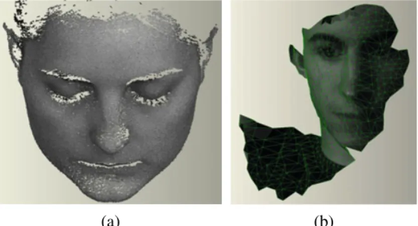
Fig. 2. (a) Registered 3D point clouds; (b) A textured mesh
until the button is released. The generated sequence consists of 3D point clouds with adjustable density acquired with variable frequency. Between 3D acquisitions, 2D im-ages can be shot by the localization camera. Inertial measurements acquired at high fre-quency allow to determine the sensor’s attitude. All these data are exploited here to fuse successive 3D views (figure 2 (left)) and to capture appearance information (grayscale or color), so that, depending on the application, the system can generate meshed and textured models (figure 2 (right)).
For an hand-held sensor context, an important challenge concerns the registration of partial data acquired from different view points. Moreover, the precision of the gen-erated 3D data is an essential consideration regarding to numerous applications; our objective is to guarantee a 0.1 mm accuracy. The next section presents our algorithms and strategies for a precise registration with no prior preparation of the object or specific material for our sensor.
3 Registration
Many approaches for registration of two 3D images Vk and Vk+l acquired respectively at instants tk and tk+lare based on the Iterative Closest Points algorithm (ICP) [2] [13]. This method aims to align two sets of 3D measurements from geometric optimization. Though ICP methods can achieve good results in finding the rigid transformation(R, t) that brings Vk+l in the reference frame of Vk, they need to be fed with a good initial estimate of this transformation. Moreover, these methods are geometry-based and are therefore dependant on the density of data.
The ICP Algorithm
Supposing it exists a good initial guess of the rigid transformation between two 3D images Vk and Vk+l, ICP method minimizes an inter-point distance criterion to align the two models. It is an iterative algorithm using a set of points {pk
i} selected in scan Vk. Each iteration is divided in :
– pairing points pk
i with nearest neighbours in scan Vk+l using a k-d tree structure, – weighting and rejecting pairs,
– estimating rigid transformation minimizing the Sum of Squared Distances (SSD)
between paired points.
The estimated transformation is then applied to align Vk+l on Vk. These steps are iter-ated until a distance convergence criterion is achieved or when a maximum number of iterations is reached.
Rejecting pairs is done using two filters. The first one ensures unicity of pairs: one point in Vk+l can be paired with only one point of Vk. During the pairing step, a can-didates list in Vk+l is built for each point pki from Vk. These lists are then browsed to ensure both unicity of the pairs and optimality in their choice, in term of 3D distance. The second filter exploits a statistical criterion based on distance distribution between paired points [21]. We therefore have a set of N noisy or unperfect pairs!pki, pk+li ". es-timating rigid transformation to align Vk and Vk+l involves minimizing the SSD score:
ϵ =#Ni=1$pki −!Rpk+li + t"%2
Arun and al. [1] proposed a least-square minimization method based on SVD decom-position to solve this problem in a closed form.
The initialization Step
Any local optimization method is exposed to the initialization problem, i.e. these meth-ods are sensitive to the quality of the initial guess. When such a guess is not available, a coarse alignment of scans has to be made first; we exploit measurements from inertial sensing and 2D images [4].
Inertial sensing allows to get attitude of the sensor at the acquisition instants; it gives a good estimate of the rotation component R of the transformation; the internal filter of the IMU device provides this attitude estimate. Making more profit of IMU measure-ments has not been considered, due to the requirement on the registration accuracy.
Exploiting 2D images that our sensor provides, we can achieve a robust interest points matching. The translation component t of the transformation is then computed using 3D points corresponding to matched interest points.
Density Dependence
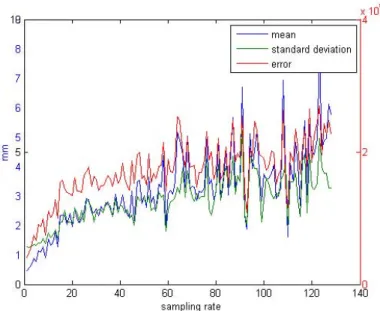
Many works in the state of the art, have proven the capacity of ICP algorithm for data alignment in euclidian space. However, this method tries to pair points and gives an estimate based on noisy measurements. The result is necessarily a compromise of pair-ing errors. With perfect matchpair-ings, the rigid transformation could be found exactly, but scans are discrete: paired points pk+l
i and pki do not correspond exactly. So the ICP re-sult is strongly dependent to the sensor resolution. Figure 3 shows that as the 3D scans are sampled, precision (and quickly convergence) can not be guaranteed.
The next section shows how a method exploiting 2D images provided by our sensor can improve scan alignment based on ICP algorithm.
Fig. 3. ICP error according to scan density
4 Image-Based Registration
The ICP-based registration method could give an inaccurate result due to the pairing method. Working on points sets exclusively is convenient in term of coding simplicity, but the accuracy depends on the scan density. To solve this problem, several methods have been proposed, for instance using a point-to-plane metric [9] or exploiting reverse calibration methods [10].
Our sensor exploits 2D images. A classical method, like bundle adjustment [19], consists in optimizing the rigid transformation and the reconstructed 3D points by di-rectly correlating projections in successive images. Using our stereo setup, this could give precise matched pixels between four images, &Iklef t, Ikright' acquired at time tk, and&Ik+llef t, Ik+lright' acquired at time tk+l. But the scene (including light) must remain invariant between acquisition instants tk and tk+l.
In our case, a speckle pattern is projected to help the stereo-correlation phase. Being hand-held, our sensor imposes the light projector to be embedded on the sensor, and therefore to move with it. It is consequently impossible to achieve a direct correlation between images Ik and Ik+lsince the lighting conditions have changed greatly.
4.1 Image-Based Pairing
Let us consider two pairs of stereo images &Iklef t, Ikright' and &Ik+llef t, Ik+lright' with a rough estimate (R, t) of the sensor motion between tk and tk+l. Images are recti-fied (distortion and epipolar rectification) and the transformation between left and right camera is fixed and calibrated. The process of 3D reconstruction based on stereo vi-sion [6], [5] has given two clouds of 3D points Vk and Vk+l. We need to feed the ICP algorithm with a set of paired 3D points!pk
i, pk+li "
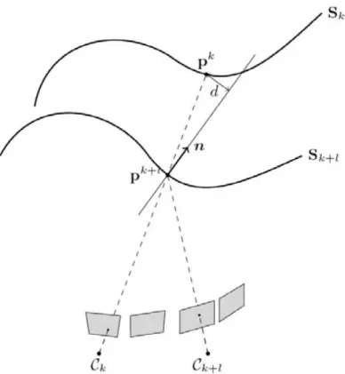
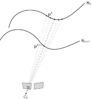
Fig. 4. Matching using our method. The surface Sk(resp. Sk+l) is reconstructed from the image pair acquired at time tk(resp. tk+l). The matching point pk+l of pkis the projection of pk+lon Sk from the view point at time tk. The weighting function applied to this pair is related to the distance from pkto the normal vector at point pk+l.
Our approach looks first for matchings between points selected in Vk, and pixels in images acquired at time tk+l. Figure 4 illustrates this process.
Firstly a set of points {pk
i} of Vk is selected from a sampling grid applied on image Iklef t according to a given sampling rate. Using the estimated sensor motion, a point pk i can be expressed in the reference frame of the sensor in its position at time tk+l. Let us note (pk+li this estimated matched point of pki: (pk+li = R−1!pki − t"
The classical ICP algorithm selects in Vk+l the closer point of (pk+li . Instead, a new correlation step is performed between Ilef t
k+l and I right
k+l in order to improve this match-ing. At first (pk+li is projected in Ilef t
k+l using the pinhole camera model: (su sv s)T = K
0 p(k+li where K0 is the calibration matrix of the rectified left camera, u and v are coordinates (with sub pixel accuracy) of a pixel in image Ilef t
k+l. Then the stereo corresponding point of(u, v) is found in Iright
k+l , using interpolation for the correlation [18]. This operation gives a disparity d between matched pixels in left and right images. A 3D point(x, y, z) is reconstructed from (u, v) and d:
⎡ ⎣dxdy dz ⎤ ⎦ = Q ⎡ ⎣uv 1 ⎤ ⎦
with Q the reconstruction matrix, which is a priori known from the stereo baseline and the intrinsic parametres of the rectified stereo sensor. pk+l
i = (xyz)T will be used for ICP, as the matched point of pk
i of Vk. If (R, t) is the exact transformation, then pk+li = (pk+li and the following equation should be verified: pk
i = Rpk+li + t 4.2 Transformation Estimation
Classical transformation estimation uses the minimisation of a SSD score based on the paired points. To help filtering bad pairs and expand the convergence basin, some additional constraints are taken into account by associating a weight to every pair.
ϵ = #Ni=1φ (i)∥pk i −
&
-Rpk+li + -t'∥2
Function φ (i) is the weighting function applied to each pair of points. The chosen weighting in our method is inspired by the normal intersection search method of Chen [3]. For each point pk+l
i , the distance from it to the normal vector of its matching point pki (figure 4) is computed. φ (i) = 1 − di
dmax , with di being the euclidean distance
between point pk+l
i and normal vector ⃗ni of the matching point pki, dmax being the maximal distance over all pairs!pk
i, pk+li "
.
4.3 Pyramidal Approach
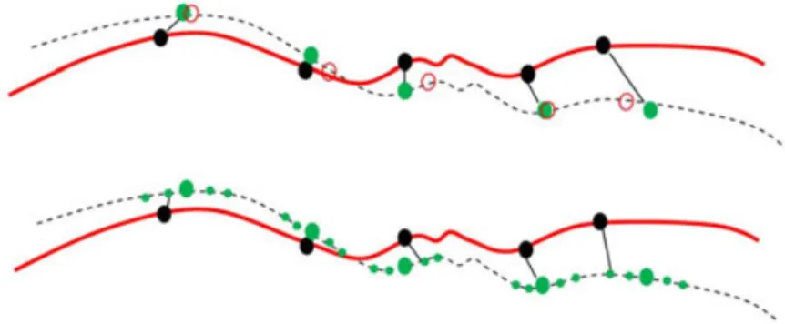
When the initial estimation of the transformation is not perfect, the selection method described in section 4.1 will not give proper results. Figure 5(top) illustrates this error. Sampled points from Vk are drawn with black circles, reconstructed points are drawn with green circles, and exact theoretical corresponding points are drawn with empty red circles. It is shown here that pairs are not matching exact corresponding points, and sometimes leading to important mistakes.
To solve this problem we propose to reconstruct several candidates to be matched with pk
i. They are obtained also by correlation between I lef t k+l and I
right
k+l , in the neigh-bourhood of the pixel (u, v), projection of (pk+li (figure 6). The size and resolution of the neighbourhood are adapted according to the convergence of the algorithm.
Fig. 6. During matching process, part of the neighbourhood of the considered image point is
reconstructed. Final matchings are determined using a point to point distance.
An iterative pyramidal approach is applied. Starting the algorithm, we choose a large window for neighbourhood, but with a sparse resolution, e.g. one can choose to recon-struct one pixel out of three in a 21 × 21 window around the projected pixel (u, v) (Figure 5(bottom)). These parameters are adapted during the algorithm to help conver-gence following a given strategy. When a set of parameters leads to converconver-gence of the estimated motion, one can reduce the neighbourhood window (from21 × 21 to 3 × 3) and increase the resolution (from one out of three, to one out of 0.5).
The key point of the method is that reducing the density to subpixel resolution allows to find more precise pairs of points. Theorically, with infinitesimal resolution, exact corresponding points will be found. Practically, the results are limited by the precision of the interpolation method used for subpixel correlation.
We show in section 5 results of our experiments using this method in comparison with classical geometric approaches.
5 Results
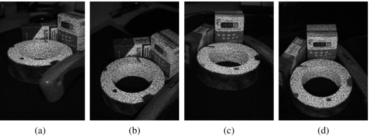
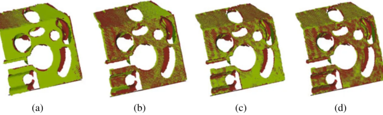
Results presented here are based on two data sets. The first one is made with scans of a mechanical object. The second set is a sequence acquired on a standard cylinder with an known internal diameter of70.004mm. Rectified pairs of images from the mechan-ical object sequence are shown on figure 7 and those from the cylinder sequence are presented on figure 8. Key features of our method are illustrated through these experi-ments. The mechanical object sequence is used to show the convergence of the method when registering two 3D views with a reduced number of points. The cylinder sequence
(a) (b) (c) (d)
Fig. 7. Stereo acquisitions of a mechanical object
(a) (b) (c) (d)
Fig. 8. Stereo acquisitions of a standard cylinder
is used to illustrate the precision gain brought by the method. More experimental results are available in [4].
5.1 Mechanical Object
For this evaluation we registered the point clouds from the mechanical object sequence using three methods : the original ICP [2], the Park method [11] and our approach.
Figure 9 shows the evolution of the ICP error on 50 iterations for the three methods. Park method proposes a fast convergence, like it was shown in [13], and a better result compared to the original ICP. Our method, in the first strategy also converges fastly. First strategy change (iteration 14) allows to reach a similar precision than Park method. Second strategy change (iteration 40) reaches subpixel precision and allows a better matching, reducing the final error.
Point clouds registered with each method are shown in figure 10. The initial position is also given in the figure. Classical ICP and Park methods allow to reach a good regis-tration but a bias can be observed. Indeed, these methods tend to converge using areas where the point density is more important, or more uniform. Here, they favor the align-ment of dominant planes. Our method allows to reach a more homogeneous registration due to our weighting constraints and because it can converge using less points (Table 1) and is, consequently less sensitive to dominant areas.
Fig. 9. RMS registration error for the mechanical test object
(a) (b) (c) (d)
Fig. 10. Registration results. (a) Initial estimate (b) ICP (c) Park method (d) Our method. Registered models have been compared to the CAD model of the object. Table 1 summarizes principal error measurements extracted from this comparison.
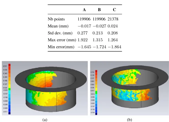
5.2 Cylinder Sequence
We present in figure 11 a comparison of results on a standard cylinder between a clas-sical geometric method and ours. Registered sequence of twenty-five acquisitions has been fitted to the exact CAD model of the cylinder; the projection error map based on point-to-surface distance between the built cloud of points and the theoretical CAD model, is built using the Geomagic Qualify v12 software. First constatation is that the error span is narrowed with our method. More than99% of the points are included in a [−154µm, 154µm] with a large majority being included in a [−50µm, 50µm]. With a classical approach a large amount of points are out of this range and are mostly included in the[−100µm, 100µm].
One can note that with a classical geometric approach, due to the error propagation, points on the border are not of good quality. With our approach, due to the precision gain, error still propagates (since we only do pair registrations series) but the divergence effect is smoothed over the cloud.
Table 1. Registration evaluation. (a) ICP (b) Park method (c) Our method. A B C Nb points 119906 119906 21378 Mean (mm) −0.017 −0.027 0.024 Std dev. (mm) 0.277 0.213 0.208 Max error (mm) 1.922 1.315 1.264 Min error(mm) −1.645 −1.724 −1.864 (a) (b)
Fig. 11. Image-based registration: (left) classical ICP, (right) our refined approach
6 Conclusion
We presented in this article an approach for precise registration of 3D images acquired from a hand-held sensor, based on a moving speckle pattern projector. We illustrated the weakness of classical geometric methods when exploiting highly-sampled data sets. A combination of geometric and image processing solutions has been proposed for a precise refinement step after a coarse initial estimate has been provided. Accuracies given by our method are complient with requirements of most industrial applications.
The method still needs to be improved to reduce the total number of iterations by adapting strategies efficiently. The method has been only validated to perform the reg-istration between two successive acquisitions; future works will focus on adaptation of this method to multiple views registration.
References
1. Arun, K.S., Huang, T.S., Blostein, S.D.: Least-squares fitting of two 3-d point sets. IEEE Trans. on PAMI 9 (1997)
2. Besl, P., McKay, N.: A method for regtration of 3-d shapes. IEEE Trans. on PAMI 14 (1992) 3. Chen, Y., Medioni, G.: Object modelling by registration of multiple range images. Image
4. Coudrin, B., Devy, M., Orteu, J.J., Br`ethes, L.: An innovative hand-held visual digitizing system for 3d modelling. Optics and Lasers in Engineering (2011)
5. Devernay, F., Faugeras, O.: Shape from stereo using fine correlation: Method and error anal-ysis. Technical report, INRIA Sophia-Antipolis (2000)
6. Hartley, R., Zisserman, A.: Multiple View Geometry in Computer Vision. Cambridge Uni-versity Press, Cambridge (2000) ISBN: 0521623049
7. Johnson, A., Herbert, M.: Surface registration by matching oriented points. In: Proc. Int. Conf. on 3-D Digital Imaging and Modeling (3DIM) (1997)
8. Li, H., Hartley, R.I.: Five-point motion estimation made easy. In: Proc. Int. Conf. on Pattern Rerognition, ICPR (2006)
9. Low, K.: Linear least-squares optimization for point-to-plane icp surface registration. Tech-nical report, University of North Carolina at Chapel Hill (2004)
10. Neugebauer, P.: Geometrical cloning of 3d objects via simultaneous registration of multiple range images. In: Proc. Int. Conf. on Shape Modeling and Applications (1997)
11. Park, S.Y., Subbarao, M.: A fast point-to-tangent plane technique for multi-view registration. In: Proc 4th Int. Conf on 3-D Digital Imaging and Modeling, pp. 276–284 (2003)
12. Sandhu, S.D.R., Tannenbaum, A.: Particle filtering for registration of 2d and 3d point sets with stochastic dynamics. In: Proc. Conf. Computer Vision and Pattern Recognition (2008) 13. Rusinkiewicz, S., Levoy, M.: Efficient variants of the icp algorithm. In: Proc. Int. Conf on
3-D Digital Imaging and Modeling (3DIM) (2001)
14. Segal, A., Haehnel, D., Thrun, S.: Generalized-icp. In: Proc. Conf. Robotics: Science and Systems (RSS), Seattle, USA (June 2009)
15. Studholme, C., Hill, D., Hawkes, D.: An overlap invariant entropy measure of 3d medical image alignment. Pattern Recognition 32 (1999)
16. Sutton, M.A., Orteu, J.J., Schreier, H.: Image Correlation for Shape, Motion and Deformation Measurements: Basic Concepts,Theory and Applications. Springer Publishing Company, In-corporated (2009)
17. Suveg, I., Vosselman, G.: Mutual information based evaluation of 3d building models. In: Proc. Int. Conf. on Pattern Rerognition (ICPR), vol. 3 (2002)
18. Th´evenaz, P., Blu, T., Unser, M.: Interpolation revisited. IEEE Trans. on Medical Imag-ing 19(7), 739–758 (2000)
19. Triggs, B., McLauchlan, P., Hartley, R., Fitzgibbon, A.: Bundle adjustment a modern synthe-sis. In: Proc. Int. Workshop on Vision Algorithms, with ICCV 1999 (1999)
20. Viola, P., Wells, W.M.: Alignment by maximization of mutual information. Int. Journal on Computer Vision, IJCV (1997)
21. Zhang, Z.: Iterative point matching for registration of free-form curves and surfaces. Int. Journal on Computer Vision (IJCV) 13 (1992)