HAL Id: hal-00451877
https://hal.archives-ouvertes.fr/hal-00451877
Submitted on 25 Jun 2019HAL is a multi-disciplinary open access archive for the deposit and dissemination of sci-entific research documents, whether they are pub-lished or not. The documents may come from teaching and research institutions in France or abroad, or from public or private research centers.
L’archive ouverte pluridisciplinaire HAL, est destinée au dépôt et à la diffusion de documents scientifiques de niveau recherche, publiés ou non, émanant des établissements d’enseignement et de recherche français ou étrangers, des laboratoires publics ou privés.
Complete shaking force and shaking moment balancing
of planar parallel manipulators with prismatic pairs
Sébastien Briot, Ilian Bonev, Clément Gosselin, Vigen Arakelian
To cite this version:
Sébastien Briot, Ilian Bonev, Clément Gosselin, Vigen Arakelian. Complete shaking force and shak-ing moment balancshak-ing of planar parallel manipulators with prismatic pairs. Journal of Multi-body Dynamics, SAGE Publications, 2009, 223 (1), pp.43-52. �hal-00451877�
Complete shaking force and shaking moment balancing of planar parallel
manipulators with prismatic pairs
S. Briot*
, I.A. Bonev*
, C.M. Gosselin† and V. Arakelian‡
*
Department of Automated Manufacturing Engineering École de technologie supérieure (ÉTS), Montreal, QC, Canada
[email protected] [email protected]
† Département de génie mécanique
Université Laval, Sainte-Foy, QC, Canada [email protected]
‡
Département de Génie Mécanique et Automatique Institut National des Sciences Appliquées (INSA), Rennes, France
ABSTRACT
This paper deals with the complete shaking force and shaking moment balancing of planar parallel manipulators with prismatic pairs. The cancellation of the dynamic loads transmitted to the ground is a challenge for these types of manipulators.
It is obvious that the classical methods based on the optimal redistribution of movable masses and additional counter-rotations can be used to cancel shaking force and shaking moment. However, such a balancing of parallel manipulators with prismatic pairs is only attained via a considerably complicated design. This paper shows that it is possible to balance planar parallel mechanisms using Scott-Russell mechanisms. Such an approach enables a division of the number of counter-rotations by two. Numerical simulations carried out using ADAMS software validate the obtained results and illustrate that the suggested balancing enables the creation of a parallel manipulator transmitting no inertia load to its base.
Index terms – Shaking force, shaking moment, balancing, planar parallel robots with prismatic
pairs.
1. INTRODUCTION
Shaking force balancing is mostly obtained via an optimal redistribution of movable masses [1-10] or adjustment of kinematic parameters [11]. The cancellation of the shaking moment is a more complicated task and can be obtained using three main different methods: (i) shaking moment balancing using counter-rotations [12-17] (Fig. 1a) (ii) shaking moment balancing by adding four bar linkages [18-22] (Fig.1b) and (iii) shaking moment balancing by optimal trajectory planning [17, 23, 24].
Previous works have been devoted to the study of parallel manipulators with revolute joints and until now, to our knowledge, no study has been carried out on complete shaking force and shaking moment balancing of parallel manipulators with prismatic pairs.
(a) balancing by adding counter-rotations [17] (b) balancing by adding four-bar linkages [18]
Figure 1. Complete shaking force and shaking moment balanced 3-RRR planar parallel manipulators.
In this paper, for the first time, we propose solutions for complete shaking force and shaking moment balancing of planar parallel manipulators with prismatic pairs. We illustrate these solutions via the 3-RPR parallel manipulator. All obtained results are validated using ADAMS software simulations.
2. COMPLETE SHAKING MOMENT AND SHAKING FORCE BALANCING BY ADDING AN IDLER LOOP BETWEEN THE BASE AND THE PLATFORM
Inertia force balancing by adding an idler loop is known to be used for 1-degree-of-freedom (DOF) mechanisms [25-29]. With regard to planar manipulators, such an approach has only been used in the balancing of gravitational and inertia forces [9, 10, 30, 31].
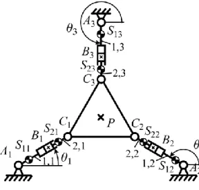
In this section, the complete shaking force and shaking moment balancing of planar manipulators by adding an idler loop is discussed. The added balancing loop is mounted between the base and the platform of the mechanism. We illustrate the suggested balancing technique on a 3-RPR mechanism (Fig. 2). Please note that we do not mention the type of actuation of the mechanism as it has no influence on the balancing.
Firstly, let us analyze the cancellation of the dynamic reactions of the 3-RPR planar parallel mechanism (Fig. 2a). Such a mechanism has 3 DOF (two translations in the Oxy plane and one rotation of the moving platform around an axis perpendicular to Oxy) and is composed of three identical legs, each being composed of a revolute joint attached to the base at point Ai (in the
remainder of this report, i = 1, 2, 3), one moving prismatic guide, located at point Bi, and another
revolute joint attached to the platform at Ci. The base and platform triangles, denoted A1A2A3 and
C1C2C3, are equilateral. On this manipulator, typically, the actuated joints are the first revolute joint at Ai or the linear guide at Bi.
(a) Schematics of the 3-RPR mechanism. (b) Schematics of the added idler loop (RRR chain).
Considering that the x axis is directed along the line A1A2, the y axis being perpendicular to the
x axis and the origin of the base frame located at point O, the centre of the circumcircle of
triangle A1A2A3, one can define the coordinate x, y and of the platform, as being respectively the coordinates of point P along the x and y axes and the angle between the line C1C2 and A1A2.
The length BiCi is denoted L1. Let us also denote as Sji the centre of mass of link ij (j = 1, 2),
which has a mass mj and an axial moment of inertia Ij. The centre of the mass of the platform is
located at point P. The mass of the platform is mp and its axial moment of inertia Ip.
In order to cancel the shaking forces and shaking moment of the manipulator, an idler loop is added between the base and the platform (Fig. 2b). The lengths EF and FP are denoted L5 and L6 respectively. The centre of mass of elements 5 and 6 of the idler loop are denoted S3 and S4 with masses m5 and m6 and axial moments of inertia I5 and I6, respectively. The positions of the centre of masses are dAiS1i = r1 L1 ui, dCiS2i = (r2–1) L1 ui,dES5 = r5 dEF, and dFS6 = r6 dFP, r1, r2, r5, and r6
being dimensionless coefficients, and ui a unit vector directed along BiCi.
Thus, considering the shaking force F of leg 1, its expression is:
6 6 5 5 3 1 2 1 S S P p i j Sji j m m m m d d d d F
(1)where dSji, dP, d and S5 d are the acceleration of the centre of mass SS6 ij, of P, of S5 and of S6
respectively.
After a simple development of expression (1), it can be seen that the shaking force F can be expressed as:
p
p
F i i m m m r m m m r m r m r m a a d F 2 6 6 4 2 5 5 6 3 1 2 2 1 1 1 3 3
(2) with i i i i i i i L sin cos cos sin 2 1 a , (3a) 6 6 2 6 6 6 6 6 4 sin cos cos sin L a , (3b)
and dF is the acceleration of point F.
At this step, only five counterweights are needed in the cancellation of the shaking force, but it could be seen after more derivations that three others are necessary for the cancellation of the shaking moment. Therefore, we propose directly adding three supplementary counterweights (Fig. 3). The positions of the eight masses are dAiMcp1i = rcp1 L1 ui, dBiMcp2i = rcp2 L1 ui,dEMcp5 = rcp5
dEF, and dFMcp6 = rcp dFP, rcp1, rcp2, rcp5, and rcp6 being dimensionless coefficients. Their masses
are respectively denoted mcp1, mcp2, mcp5 and mcp6. With the addition of the counterweights, the
shaking force becomes:
cp cp
cp cp cp
F i i cp cp cp cp bal r m m r m r m r m a a d F F 6 6 4 6 5 5 3 1 2 2 1 1 1
(4)Thus, the shaking force is cancelled if:
1 1 1 1 cp cp r r m m , (5a)
2 2 2 2 1 1 cp cp r r m m , (5b)
6 6 6 2 2 6 3 cp p cp cp r m r m m m m , (5c) and
5 5 5 6 6 2 2 5 3 cp cp p cp cp r m r m m m m m m . (5d)The expression of the shaking moment MO of the modified structure (expressed at point O) can
be written as:
dt dH
M O
O , (6)
where HO is the angular momentum of the leg (expressed at point O). Thus, in order to cancel the
shaking moment, the angular momentum is held constant over time. The expression of the angular momentum HO is:
6 5 3 1 2 1 3 1 2 1 j j j OMj OMj OMj OMj cpj OSj OSj OSj OSj j p i j OMji OMji OMji OMji cpj i j i j OSji OSji OSji OSji j O I x y y x m x y y x m I x y y x m I x y y x m H
(7)where xOQ, yOQ, xOQ and yOQ are the position and velocities of any point Q along x and y axes,
respectively, Q being either point Sji, Mji, (j = 1, 2), Sj or Mj (j = 5, 6).
Developing and introducing (5) into (7) yields
5 2 5 2 2 5 2 5 6 6 2 5 5 2 5 5 5 6 2 6 2 2 2 6 6 2 6 6 6 2 2 2 3 1 2 1 2 2 2 3 1 2 1 2 2 2 2 1 1 2 1 1 2 1 3 3 3 1 1 L m m L m m m r m r m I L m m m r m r m I R m m I L r m L r m r m r m I I H cp p cp cp cp cp p cp cp p cp p i i cp cp i i cp cp O
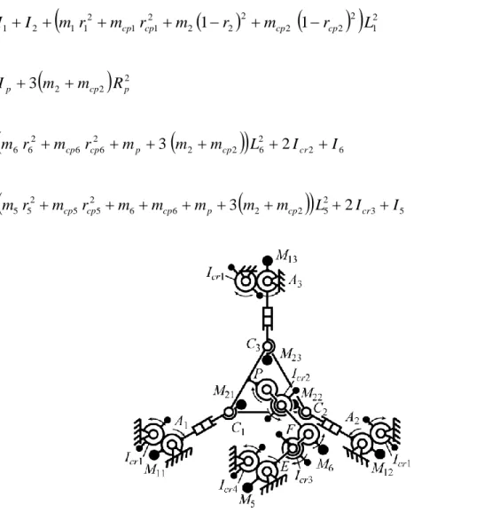
(8)After such modifications of the RRR chain, the angular momentum of the legs of the mechanism and of the RRR chain can be balanced using six counter-rotations (Fig. 3), which have an axial moment of inertia equal to:
2 1 2 2 2 2 2 2 2 1 1 2 1 1 2 1 1 I I m r m r m 1 r m 1 r L Icr cp cp cp cp (9a)
2 2 2 2 p 3 cp p cr I m m R I (9b)
2 6 2 6 2 2 2 6 6 2 6 6 3 m r m r m 3 m m L 2I I Icr cp cp p cp cr (9c)
3 5 2 5 2 2 6 6 2 5 5 2 5 5 4 m r m r m m m 3 m m L 2I I Icr cp cp cp p cp cr (9d)Figure 3. Schematics of the 3-RPR mechanism with the added RRR chain used for the cancellation of the shaking force and shaking moment.
Numerical application
Let us illustrate the suggested balancing approach using numerical simulations carried out with ADAMS software. For this purpose, non balanced and balanced 3-RPR parallel manipulators will be compared.
The chosen trajectory for simulations is a straight line of the controlled point of the platform, achieved in tf = 0.25 s, between P0 = (x0, y0) = (–0.05 m, 0) and Pf = (xf, yf) = (–0.2 m, 0) with a
rotation of the platform from 0 = 0° to f = 30°. For the displacement of the mechanism, fifth
order polynomial laws are used and therefore the trajectory is defined by the following expressions:
3
4
5
0 0 xf x 10 t/tf 15 t/tf 6 t/tf x t x , (10a)
t 0 y , (10b)
3
4
5
0 0 f 10 t/tf 15 t/tf 6 t/tf t . (10c)The parameters used for the simulations are the following:
- radii of the circumcircles of the base triangle A1A2A3 and the platform triangle C1C2C3 ,Rb
= 0.35 m, Rp = 0.1 m; - L1 = 0.05 m; L5 = 0.15 m; L6 = 0.1581 m; - r2 = r5 = r6 = 0.5; r1 = 2; - m1 = 0.75 kg; m2 = 0.37 kg; m5 = 0.42 kg; m6 = 0.47 kg; mp = 1 kg; - I1 = 0.00344 kg.m²; I2 = 0.00025 kg.m²; I5 = 0.00122 kg.m²; I6 = 0.00146 kg.m²; Ip = 0.00436 kg.m²;
- point E is located at point O.
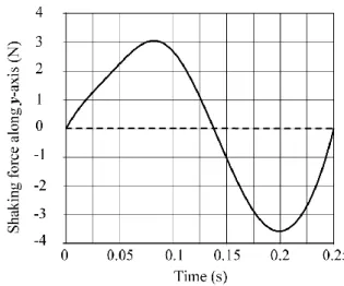
For such parameters and such a trajectory, the shaking force and shaking moment are computed using ADAMS software and are presented in Fig. 4 (solid line). Then, we add the counterweights and the idler loop EFP to the mechanism. The position coefficients of the counterweights are all equal to rcpj = 0.5 (j = 1, 2, 5, 6). Therefore, the added masses are equal to mcp1 = 0.75 kg, mcp2 =
0.37 kg, mcp5 = 6.92 kg, mcp6 = 21.66 kg. The new values of the shaking force and moment are
shaking efforts are cancelled, while the maximal value of shaking moment is increased by a factor 17. Finally, we add the counter-rotations. Their values are equal to Icr1 = 0.01917 kg.m²,
Icr2 = 0.02665 kg.m², Icr3 = 0.18169 kg.m², Icr4 = 0.72781 kg.m². With such counter-rotations, the
shaking moment is balanced (in gray line in Fig. 4c).
(a) shaking force along x-axis (b) shaking force along y-axis
(c) shaking moment along z-axis
Figure 4. Shaking force and shaking moment before (solid line) and after (dashed line) the addition of the counterweights, and after the addition of the counter-rotations (gray line).
3. COMPLETE SHAKING FORCE AND SHAKING MOMENT BALANCING VIA SCOTT-RUSSELL MECHANISM
In this section another approach for complete shaking force and shaking moment balancing is developed, which consists of adding Scott-Russell mechanisms to the initial architecture of a manipulator. This approach enables a reduction in the number of counter-rotations.
3.1. Properties of the Scott-Russell mechanism.
Firstly, let us observe a simple slider-crank mechanism (Fig. 5). Let us denote the lengths AB and BC as respectively L1 and L2, andthe centre of masses of link i (i = 1, 2, 3) as Si, which has a
mass mi and an axial moment of inertia Ii. The positions of the centres of mass are dAS1 = r1 dAB,
dAS2 = dAB + r2 dBC,dAS3 = dAC + dCS3, r1 and r2 being dimensionless coefficients, dCS3 = L3 r3 x, (L3 is a constant).
Figure 5. A general slider-crank mechanism.
It is known that the compete shaking force and shaking moment balancing of a general slider-crank mechanism can be obtained by adding two counterweights mounted on the links and two pairs counter-rotation inertia-counterweights. However, it is possible to balance this mechanism
without counter-rotation inertia-counterweights if it has specific geometrical parameters, as in Scott-Russell mechanisms (a=0, L1=L2).
Let us consider the balancing of this mechanism. The expression of the shaking force F of a slider-crank mechanism can be written as:
3 1 i Si i m d F (11)where d is the acceleration of the centre of mass SSi i.
Developing (11), the expression of F becomes:
d
a F m1r1m2 B m2r2 m3 (12) with 2 2 2 2 2 2 2 2 sin cos cos sin L a . (13) Bd is the acceleration of point B.
The constant terms of eq. (12) can be cancelled by the addition of two counterweights Mj, (j =
1, 2) (Fig. 5), of which the masses are mcpj. Their positions are: dAMcp1 = rcp1 dAB, dBMcp2 = rcp2 dBC,
rcp1 and rcp2 being dimensionless coefficients. With the addition of the counterweights, the
shaking force becomes:
d a F F cp1 cp1 cp2 B cp2 cp2 bal r m m r m (14)Thus, the shaking force vanishes if:
2 3 2 2 2 cp cp r m r m m and 1 3 2 2 1 1 1 cp cp cp r m m m r m m . (15)
The expression of the angular momentum HA (expressed at point A) is:
2 1 3 1 j MSj MSj MSj MSj cpj j j j ASj ASj ASj ASj j A m x y x y I m x y x y H (16)where xAQ, yAQ, xAQ and yAQ are the position and velocities of any point Q along x and y axes,
respectively, Q being either point Sj or Mj (j = 1, 2, 3).
Developing and introducing (15) into (16),
2 2 2 3 2 2 2 2 2 2 2 1 2 1 3 2 2 2 1 1 2 1 1 1 m r m r m m m L I m r m r m L I HA cp cp cp cp cp (17) with
2 2 2 L x x y a x x yAB AC AB AB AC AB . (18)where xAC, xAB, yAB are the coordinates of points C and B, respectively, and xAC, xAB, yAB their
velocities.
In order to cancel the shaking moment MA, the angular momentum has to be constant or null.
Developing (18), one notices that this can be obtained if:
a = 0 and L1 = L2. (19)
In such a case, 12. Therefore, the shaking moment is cancelled if:
12 0 2 2 2 2 2 2 2 2 1 2 2 2 1 1 2 1 1 1 m r m r m m L I m r m r L I cp cp cp cp cp (20)3.2. Balancing of a manipulator’s leg using a Scott-Russell mechanism.
Now let us consider a manipulator’s leg with an added Scott-Russell mechanism (Fig. 6). Let us denote as S4 the centre of mass of link 4, which has a mass m4 and an axial moment of inertia I4. The position of S4 is: dCS4 = L3 r4 u, r4 being a dimensionless coefficient and u a unit vector along
dCS3.
Figure 6. A manipulator leg with added Scott-Russell mechanism.
Now the shaking force becomes:
1 1 1 1 2 2 3
d
3 3 4 4
a1
2 2 2 2 3
a2 F m r mcp rcp m mcp m B m r m r m r mcp rcp m (21) with 03 03 2 03 03 03 03 3 1 sin cos cos sin L a (22) and
41 03 41 03 2 03 03 41 03 41 03 41 03 1 2 sin cos cos sin L a . (23)At this step, only one counterweight is needed for the cancellation of the shaking force, but it could be seen after more derivations that another is necessary for the cancellation of the shaking moment. Therefore, we propose adding this supplementary counterweight directly. The positions
of the two masses are: dAMcp3 = rcp3 L3 u, dCMcp4 = rcp4 L3 u, rcp3 and rcp4 being dimensionless
coefficients. Their masses are respectively denoted mcp3 and mcp4. With the addition of the
counterweights, the shaking force becomes:
3 3 4 4
2 1 3 3d a a F F cp B cp cp cp cp cp bal r m r m m m . (24)Thus, the shaking force is cancelled if:
4 4 4 4 cp cp r r m m , (25a) 3 3 3 3 cp cp r r m m , (25b) 2 3 3 2 2 2 cp cp cp r m m r m m (25c) and 1 3 3 2 2 1 1 1 cp cp cp cp r m m m m r m m . (25d)
Developing and simplifying, the expression of the angular momentum is:
41 2 03 1 eq eq A I I H (26) with
2 3 2 4 4 2 4 4 2 3 3 2 3 3 4 3 2 1 2 1 2 2 2 2 2 2 2 1 1 2 1 1 1 1 1 L r m r m r m r m I I I I L r m r m r m r m I cp cp cp cp cp cp cp cp eq (27)
2 1 2 2 2 2 2 2 2 2 1 2 2 2 1 1 2 1 1 1 2 I m r m r m m L I m r m r L Ieq cp cp cp cp cp . (28)From (20), Ieq2 = 0. Therefore, the shaking moment of the slider-crank can be cancelled using a
simple counter-rotation Icr with an axial moment of inertia equal to Ieq1.
3.3. Shaking moment and shaking force balancing of the 3-RPR manipulator
Now, let us apply such an approach to the 3-RPR mechanism. First of all, let us substitute the platform mass by three points masses located at C1, C2 and C3, with the values of mass equal to
mp1, mp2 and mp3 respectively [13, 31, 32]. Such a condition can be obtained if:
3 /
p pi m
m and Ip 3mpiRp2. (29)
where Rp is the radius of the circumcircle of C1C2C3. Such a decomposition of the platform enables us to consider the shaking force and shaking moment balancing of each leg of the mechanism. Then, modifying each leg in order to obtain a mechanism similar to a slider-crank linkage, (i.e., by adding an idler loop to each leg), the shaking force and shaking moment are cancelled if: 4 4 4 4 cp cp r r m m , (30a) 3 3 3 3 cp pi cp r m r m m , (30b) 2 3 3 2 2 2 cp pi cp cp r m m m r m m , (30c) 1 3 3 2 2 1 1 1 cp pi cp cp cp r m m m m m r m m , (30d)
2 1 2 2 2 2 2 2 2 2 1 2 2 2 1 1 2 1 1 1 0I m r mcp rcp m mcp L I m r mcp rcp L , (30e)and
2 3 2 4 4 2 4 4 2 3 3 2 3 3 4 3 2 1 2 1 2 2 2 2 2 2 2 1 1 2 1 1 1 1 L m r m r m r m r m I I I I L r m r m r m r m I pi cp cp cp cp cp cp cp cp cr (30f)taking into account that Icr is the axial moment of inertia of the counter-rotations (Fig. 7).
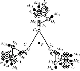
Thus, with this approach it is possible to create a fully-balanced shaking force and shaking moment 3-RPR mechanism with only three counter-rotations (Fig. 7), i.e., this method enables a reduction in the number of counter-rotations by a factor of two.
Figure 7. Schematics of a shaking force and shaking moment balanced 3-RPR mechanism.
3.4. Numerical application
The parameters used for the simulations are the followings:
- radii of the circumcircles of the base triangle A1A2A3 and the platform triangle C1C2C3 Rb
= 0.35 m, Rp = 0.1 m;
- r1 = r2 = 0.5; r3 = 0; r4 = 4;
- m1 = 1.09 kg; m2 = 1.1 kg; m3 = 0.37 kg; m4 = 0.75 kg; mp = 1 kg;
- I1 = 0.00738 kg.m²; I2 = 0.58389 kg.m²; I3 = 0.00344 kg.m²; I6 = 0.00025 kg.m²; Ip = 0.01
kg.m².
For these new parameters and for the trajectory used previously, taking into account that the position coefficients of the counterweights are equal to rcpj = -0.5 (j = 1, 3, 4), rcp2 = -1, the new
values of the counterweights are: mcp1 = 3.17 kg, mcp2 = 11.71 kg, mcp3 = 0.33 kg, mcp4 = 0.75 kg.
The shaking force and shaking moment are then computed (dashed line in Fig. 8). It is possible to see that, with the counterweights, the shaking efforts are cancelled, while the maximal value of the shaking moment is increased by a factor 28. Finally, we add the counter-rotations. Their values are equal to Icr = 1.56907 kg.m². With such counter-rotations, the shaking moment is
balanced (gray line in Fig. 8c).
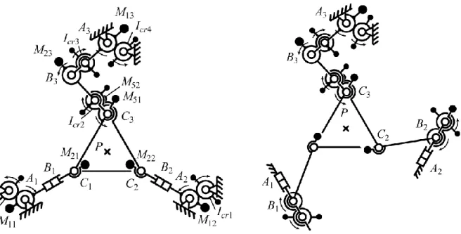
Finally, it should be noted that the combination of the proposed two techniques of balancing enables the creation of fully balanced parallel manipulators with modified legs. As examples, different structures of balanced manipulators are presented in Fig. 9 (3-RPR, 3-PRR and 3-PRP) in which one leg with a prismatic pair is replaced by a leg with only revolute joints. Such a modification allows displacing the centre of mass of the manipulator to C3 and then to balance the manipulator via the modified leg C3 B3 A3.
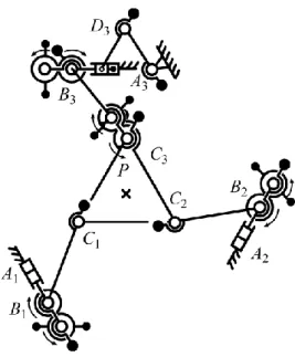
In the same way, it is possible to balance a parallel manipulator with prismatic pairs by adding fewer Scott-Russell mechanisms. The balancing schemes for several parallel manipulators are presented in Fig. 10.
(a) shaking force along x-axis (b) shaking force along y-axis
(c) shaking moment along z-axis
Figure 8. Shaking force and shaking moment, before (solid line) and after (dashed line) the addition of the counterweights, and after the addition of the counter-rotations (gray line).
a) Modified 3-RPR parallel manipulator b) Modified 3-PRR parallel manipulator
c) Modified 3-PRP parallel manipulator
Figure 9. Complete shaking force and shaking moment balancing of planar manipulators with prismatic pairs via structural modification of one leg.
a) Balancing of 3-RPR parallel manipulator b) Balancing of 3-PRR parallel manipulator
c) Balancing of 3-PRP parallel manipulator
Figure 10. Complete shaking force and shaking moment balancing of planar manipulators with prismatic with reduced number of Scott-Russell mechanisms.
4. CONCLUSIONS
This paper presents the complete shaking force and shaking moment balancing of planar parallel manipulators with prismatic pairs. Two approaches are discussed: balancing via adding an idler loop mounted between the platform and the base of the manipulator and balancing via the Scott-Russell mechanism, which enables a reduction in the number of counter-rotations by a factor of two. All studied balancing techniques are validated by simulations carried out using ADAMS software. The obtained results show that parallel manipulators balanced using the suggested methods transmit no inertia loads to their bases, i.e., the sum of all ground forces and their moments are zero.
Finally, we would like to mention that using Scott-Russel mechanisms remains using some modified 3-RRR manipulator. Thus, if we do not consider the type of actuation, the prismatic guides could be suppressed and our work could be of no interest. But the goal of our study is to propose the complete shaking force and shaking moment balancing of manipulators for applications where an actuation via a prismatic motor is needed, such as in high load carrying (using hydraulic devices). Therefore, we think the proposed solutions are of great interest to the scientific community.
REFERENCES
1 Lowen, G.G., Tepper, F.R. and Berkof, R.S. Balancing of linkages - an update. Mechanism
and Machine Theory, 1983, 18(3), 213–230.
2 Arakelian, V. and Smith, M. Shaking force and shaking moment balancing of mechanisms: an historical review with new examples. Journal of Mechanical Design, 2005, 127(2), 334– 339 (see also ERRATUM. 2005, 127(5), 1034–1035).
3 Arakelian, V., Dahan, M. and Smith, M.R. A historical review of the evolution of the theory on balancing of mechanisms. International Symposium on History of Machines and
Mechanisms - Proceedings HMM2000, Kluwer Academic Publishers, Dordrecht/Boston/
London, 2000, pp. 291–300.
4 Agrawal, S.K. and Fattah, A. Reactionless space and ground robots: novel designs and concept studies. Mechanism and Machine Theory, 2004, 39(1), 25–40.
5 Wang, J. and Gosselin, C.M. Static balancing of spatial three-degree-of-freedom parallel mechanisms. Mechanism and Machine Theory, 1999, 34(3), 437–452.
6 Newman, W.S. and Hogan, N. The optimal control of balanced manipulators. Proc. winter
annual meeting of the ASME, 1986, Anaheim, California.
7 Laliberté, T., Gosselin, C.M. and Jean, M. Static balancing of 3-DOF planar parallel mechanisms. IEEE/ASME Transactions on Mechatronics, 1999, 4(4), 363–377.
8 Fujikoshi, K. Balancing apparatus for jointed robot. Japanese Patent JP51-122254, 26 October 1976.
9 Wang, J. and Gosselin, C.M. Static balancing of spatial four-degree-of-freedom parallel mechanisms. Mechanism and Machine Theory, 2000, 35(4), 563–592.
10 Russo, A., Sinatra, R. and Xi, F. Static balancing of parallel robots. Mechanism and
Machine Theory, 2005, 40(2), 191–202.
11 Ouyang, P. and Zhang, W.J. Force Balancing of Robotic Mechanisms based on Adjustment of Kinematic Parameters. ASME Journal of Mechanical Design, 2005, 127(3), 433-440. 12 Berkof, R.S. Complete fore and moment balancing of inline four-bar linkages. Mechanism
and Machine Theory, 1973, 8(3), 397–410.
13 Arakelian, V. and Smith, M.R. Complete shaking force and shaking moment balancing of linkages. Mechanism and Machine Theory, 1999, 34(8), 1141–1153.
14 Dresig, H., Naake, S. and Rockausen, L. Vollständiger und harmonischer Ausgleich ebener Mechanismen. VDI Verlag, Düsseldorf, 1994.
15 Herder, J.L. and Gosselin, C.M. A counter-rotary counterweight for light-weight dynamic balancing. Proc. ASME 2004 DETC/CIEC Conference, 28 September – 2 October 2004, Salt Lake City, Utah, USA, pp. 659–667.
16 Kochev, I.S. General theory of complete shaking moment balancing of planar linkages: a critical review. Mechanism and Machine Theory, 2000, 35(11), 1501–1514.
17 Fattah, A. and Agrawal, S.K. On the design of reactionless 3-DOF planar parallel mechanisms. Mechanism and Machine Theory, 2006, 41(1), 70–82.
18 Ricard, R. and Gosselin, C.M. On the development of reactionless parallel manipulators.
Proc. ASME 2000 DETC, 10–13 September 2000, Baltimore, Maryland, USA.
19 Wu, Y. and Gosselin, C.M. On the synthesis of a reactionless 6-DOF parallel mechanism using planar four-bar linkages. Proc. Workshop on Fundamental Issues and Future Research
Directions for Parallel Mechanisms and Manipulators, 3–4 October 2002, Quebec City,
Quebec, Canada.
20 Gosselin, C.M., Côté, G. and Wu, Y. Synthesis and design of reactionless three-degree-of-freedom parallel mechanisms. IEEE Transaction on Robotics and Automation, 2004, 20(2), 191–199.
21 Foucault, S. and Gosselin, C.M. Synthesis, design, and prototyping of a planar three degrees-of-freedom reactionless parallel mechanism. Journal of Mechanical Design, 2004, 126(6), 992–999.
22 Wu, Y. and Gosselin, C.M. Design of reactionless 3-DOF and 6-DOF parallel manipulators using parallelepiped mechanisms. IEEE Transaction on Robotics and Automation, 2005, 21(5), 821–833.
23 Papadopoulos, E. and Abu-Abed, A. Design and motion planning for a zero-reaction manipulator. Proc. IEEE International Conference on Robotics and Automation (ICRA) , 1994, San Diego, CA, USA, pp. 1554–1559.
24 Arakelian, V. and Briot, S. Dynamic balancing of the SCARA robot. The 17th
CISM-IFToMM Symposium on Robot Design, Dynamics, and Control (RoManSy 2008), 5–9 July
2008, Tokyo, Japan.
25 Bagci, C. Complete shaking force and shaking moment balancing of link mechanisms using balancing idler loops. ASME Journal of Mechanical Design, 1982, 104, 482-493.
26 Frolov, K.V. Theory of mechanisms and machines. Moscow, ed. Vishaya shkola, 1987.
27 Doronin, V.I. and Pospelov, A.I. Balanced slider-crank mechanism”, Patent SU1627769, 15 February 1991.
28 Hilpert, H. Weight balancing of precision mechanical instruments. Mechanisms, 1968, 3(4), 289-302.
29 Arakelian, V. Equilibrage dynamique complet des mécanismes. Mechanism and Machine
Theory, 1998, 33(4), 425–436.
30 Leblond, M. and Gosselin, C.M. Static balancing of spatial and planar parallel manipulators with prismatic actuators. Proc. ASME 1998 DETC Conference, 1998, Atlanta, Georgia, USA , pp. 1-12.
31 Baradat, C., Arakelian, V., Briot, S. and Guegan, S. Design and prototyping of a new balancing mechanism for spatial parallel manipulators. ASME Journal of Mechanical Design, 2008, (to be published).
32 Seyferth, W. Massenersatz duch punktmassen in räumlichen getrieben. Mechanism and
33 Wu, Y. and Gosselin, C.M. On the dynamic balancing of multi-DOF parallel mechanisms with multiple legs. Transaction of the ASME. Journal of Mechanical Design, 2007, 129(2), 234-238.
List of figures
Figure 1. Complete shaking force and shaking moment balanced 3-RRR planar parallel manipulators.
Figure 2. Schematic of the 3-RPR robot under study.
Figure 3. Schematics of the 3-RPR mechanism with the added RRR chain used for the cancellation of the shaking force and shaking moment.
Figure 4. Shaking force and shaking moment before (solid line) and after (dashed line) the addition of the counterweights, and after the addition of the counter-rotations (gray line).
Figure 5. A general slider-crank mechanism.
Figure 6. A manipulator leg with added Scott-Russell mechanism.
Figure 7. Schematics of a shaking force and shaking moment balanced 3-RPR mechanism. Figure 8. Shaking force and shaking moment, before (solid line) and after (dashed line) the addition of the counterweights, and after the addition of the counter-rotations (gray line).
Figure 9. Complete shaking force and shaking moment balancing of planar manipulators with prismatic pairs via structural modification of one leg.
Figure 10. Complete shaking force and shaking moment balancing of planar manipulators with prismatic with reduced number of Scott-Russell mechanisms.