Elsevier Editorial System(tm) for Fire Safety Journal Manuscript Draft
Manuscript Number: FISJ-D-10-00023R1
Title: SEISMIC-INDUCED FIRE RESISTANCE OF COMPOSITE WELDED BEAM-TO-COLUMN JOINTS WITH CONCRETE FILLED TUBES
Article Type: Research Paper
Keywords: Performance-based engineering, fire, safety, seismic, steel-concrete composite beam-to-column joint, welded connection, concrete-filled tube.
Corresponding Author: Assistant Professor Raffaele Pucinotti, Assistant Professor Corresponding Author's Institution:
First Author: Raffaele Pucinotti, Assistant Professor
Order of Authors: Raffaele Pucinotti, Assistant Professor; Oreste S Bursi, Full Professor; Jean-Marc Franssen, Full Professor; Tom Lennon, Principal Consultant
Abstract: Major earthquakes in urban areas have often been followed by significant fires causing extensive damage to property. Therefore, a seismic-induced fire is a scenario that should be properly addressed in performance-based engineering. In this paper numerical and experimental results of welded steel-concrete composite full strength beam-to-column joints under post-earthquake fire are described, as part of a European project aimed at developing fundamental data and prequalification design guidelines of ductile and fire resistant composite beam-to-column joints with concrete filled tubes. In detail, seismic and fire analyses were used to design moment resisting frames endowed with the proposed joint typology. A total of six specimens were designed and subjected both to monotonic and cyclic lateral loads. The specimens were subassemblages of beam-to-column joints and performed well. Since the scope of the project was to promote joint typologies able to survive a seismic-induced fire, some specimens were pre-damaged, before being subjected to fire loadings, by imposing monotonic loads equivalent to damage levels induced by seismic loadings. Thus after fire testing, valuable information was obtained about the performance of the proposed joint typology and the adequacy of the concurrent seismic and fire design was demonstrated.
Replies to reviewers
Reviewer 1 - Comments to the Authors:
This paper firstly did a seismic design of the composite welded beam-to-column joints with concrete filled tubes, and then a numerical study of the joints in elevated temperature is conducted following with pre-damage tests and fire tests of the joints. The research is interesting and it meets the criterion. But it is better to make revision before publication. Following are some comments or questions for the authors.
1. The results of Fig.5 and Fig. 8 are from 30 mins' fire exposure. I think 30 mins's fire exposure is not enough because the sagging effect of steel sheeting may tell a different story.
2. Regarding with the results in Table 4, it's not clear about the criteria on when to terminate test.
3. From Table 4, the Max. load and deflection of D-EWJ-P3 are much larger than those of D-EWJ-S3.
4. There are some mistakes in Table 5.
5. What's SFC stands for in Fig. 12 and Fig.13?
6. In Fig. 12, why the temperature of TC12 is larger than TC11 and TC10 in the beginning? 7. In Fig. 13, why the temperature of TC10 is the highest? Is this reasonable that TC10 is
higher than TC11?
Replies to Reviewer 1 comments.
The authors thank the reviewer that provides the opportunity to improve and clarify some items described in the proposed article.
On the basis of the reviewer’s comments the following actions were performed.
1. The 30 min fire exposure were only used to highlight the behaviour of both frames and beam-to-column joints, respectively. In a greater detail as stated in the Section Introduction, both frames and joints were designed to guarantee an adequate fire resistance of at least 15 minutes of fire exposure for time to escape.
2. The tests were terminated when the load-displacement relationships imposed onto the specimens generated damage values equivalent to those values reported in the new Table 2. This procedure is clearly explained in Subsection 3.1.
3. This is the case because one can observe from the new Table 2, that the damage associated with the specimen D-EWJ-P3, i.e. 0.50, is larger than the value of 0.31 associated with the specimen D-EWJ-S3.
4. These mistakes were corrected in the new Table 3.
5. The acronym SFC stands for ISO 834 Standard Fire Curve. It is defined in Subsection 3.2. 6. These trends are a consequence of both the furnace setting and burner position. As stated in
Subsection 4.2, the temperature revealed by sensors also depends on the relative position between burner and sensors; inevitably, temperature is higher for sensors closer to the burner.
7. The considerations reported in the previous reply apply to these measurements too. Detailed Response to Reviewers
Additional replies to remarks made in the text.
a) Q: How to tell from Fig 9c the phenomena that “beam flange buckling into the adjacent composite beams” ?
R: As stated in Subsection 2.2 composite beam-to-column joints were conceptually designed to be rigid and full strength. Hence, plastic hinges were forced to form in adjacent beams. Experimental results and Figure 9 confirm this trend. Nevertheless as required by Reviewer 2 both Subsection 4.1 and Fig. 9 were removed.
Reviewer 2 - Comments to the Authors:
This paper presents a useful work investigating the seismic-induced fire behavior of beam-to-column joint. The following suggestions/comments should be considered before this paper can be accepted for publication:
1. Section 2.2.: There are two solutions provided for the application of Nelson stud in the column. Show the difference and conclusion.
2. Section 3.1 and Section 4.1: These sections presented the introduction and results of seismic tests, but they are not related to the fire tests (the specimens used in fire tests were from pre-damaged tests shown in Section 3.2 and Section 4.2). Hence, it is better to delete Section 3.1 and Section 4.1, and just give the reference.
3. Section 3.2: The equivalent static load for seismic load was used in the pre-damaged test. The authors should provide the calculation and the loading procedure.
4. Section 4.2: The numerical analysis for the pre-damaged test was performed. The authors should show the spring properties of the joints used in the numerical model. The results of pre-damaged tests should be summarized. At least, the amount of damaged should be quantified for numerical analysis. The fire performance of the joints depends on the amount of damage in the joint due to earthquake.
5. Section 4.3: Provide figures showing the failure modes of the joints, and compare the difference between pre-damaged and undamaged specimens.
6. It is important to describe the fire behavior of beam-to-column joints, in particularly from the fire tests, showing clearly the loading procedure, boundary conditions, and their effects on the fire resistance of joint, and so on.
7. Missing information should be provided. Some are highlighted below:
There is no analytical work presented in this paper;
Figures showing the loading conditions of FS2, FS3, FS4 are not given; Section 3.3: "IWJ-S1 and IWJ-S3 were pre-damaged" should be "IWJ-S1, FD-EWJ-S3, FD-IWJ-P1 and FD-EWJ-P3 were pre-damaged";
Replies to Reviewer 2 comments.
The authors thank the reviewer that provides the opportunity to improve and clarify some items described in the proposed article.
On the basis of the reviewer’s comments the following actions were performed.
1. The solution with 19 mm Nelson stud connectors welded around the column was finalized to increase the level of friction between the concrete slab and the composite column. As a result, the load transfer based on the strut mechanism shown in Fig. b) below was enhanced. This statement was clearly reported in Subsection 2.2. Relevant FE-based stress distributions based on different friction coefficients are depicted below, where a friction coefficient of 1 corresponds to the presence of horizontal shear studs around the column. For brevity, this figure was not reported in the paper.
With regard to different joints performances without and with shear studs, we must recall that composite beam-to-column joints were designed to be rigid and full strength. Hence, no remarkable differences were traced in the responses, because plastic hinges formed in adjacent beams. Further information can be found in Ref.[20].
a) 80 °
F
R d11
/2
F
R d21
/2
F
R d2 b)Fig. Distribution of compression stresses in the slab for: (a) friction coefficient equal to 0,35; b) friction coefficient equal to 1.
2. Both Section 3.1 and 4.1 were removed. Relevant references [19] and [20] were mentioned.
3. The new Table 2 reports the damage associated with all specimens as provided by FE analyses of moment resisting frames cited in the new Subsection 3.1. Because it was unfeasible to transport damaged specimens overseas and not possible to perform cyclic tests on new specimens by the partner BRE, equivalent vertical forces were applied to them, in order to produce the equivalent damage required from Table 2.
4. For each type of beam-to-column joint, i.e. with prefabricated slab or with a slab with steel sheeting, a FE model depicted in the new Fig. 9 was used to calibrate the spring properties on the basis of experimental data. These considerations were reported in Subsection 4.1. For instance, a piecewise linear moment-rotation relationship of an interior joint endowed with a slab with steel sheeting is depicted below:
-1200 -800 -400 0 400 800 1200 -200 -150 -100 -50 0 50 100 150 200 Moment [kNm] Rotation [mrad] Moment vs Rotation (Steel sheeting slab)
Relevant stiffness values are reported in the companion table. Additional information was stated in the new Subsection 4.1. As far as damage values associated with
specimens are concerned, they were reported in the new Table 2.
5. New pictures capable to show failure modes of a pre-damaged joint endowed with a steel sheeting slab were added in a new Figure 11.
With regard to the comparison between failure modes of pre-damaged and undamaged specimens, no practical difference was found. In fact, damage values of Table 2 indicate that damage is limited and repairable in agreement with the classification provided in [31]. This reference was added in Subsection 4.1.
6. The new Figure 14 clearly shows the testing set-up with loading positions and boundary conditions. In addition, the loading combination applied according to EN EN 1990 and EN1991-1-2 consisted in:
d K j K d G Q A E
, 2,1 ,1 ,in this respect see the new Subsection 3.2. Reviewer’s suggestions were introduced in Subsections 2.1. Other mistakes were removed.
Additional replies to remarks made in the text.
a) Q: Provide the reference – New Subsection 3.2
R: As stated in the Section Introduction for seismic-induced fire, both frames and joints were designed to guarantee an adequate fire resistance of at least 15 minutes of fire exposure for time to escape. This performance requirement was agreed among the partners of the PRECIOUS project. See Ref. [20].
SEISMIC-INDUCED FIRE RESISTANCE OF COMPOSITE WELDED
BEAM-TO-COLUMN JOINTS WITH CONCRETE FILLED TUBES
R. Pucinotti1, O. S. Bursi2, J-M. Franssen3, T. Lennon4
1
Assistant Professor, Dept. of Mechanics and Materials, Mediterranean University of Reggio Calabria,
Italy
2
Professor, Dept. of Mechanical and Structural Engineering, Trento University, Trento, Italy
3
Professor, Dept. of Architecture, Geology, Environment and Construction, University of Liege, Liege,
Belgium
4
Principal Consultant, Building Research Establishment Ltd, Garston, United Kingdom
Abstract
Major earthquakes in urban areas have often been followed by significant fires causing extensive
damage to property. Therefore, a seismic-induced fire is a scenario that should be properly addressed
in performance-based engineering. In this paper numerical and experimental results of welded
steel-concrete composite full strength beam-to-column joints under post-earthquake fire are described,
as part of a European project aimed at developing fundamental data and prequalification design
guidelines of ductile and fire resistant composite beam-to-column joints with concrete filled tubes. In
detail, seismic and fire analyses were used to design moment resisting frames endowed with the
proposed joint typology. A total of six specimens were designed and subjected both to monotonic and
cyclic lateral loads. The specimens were subassemblages of beam-to-column joints and performed
well. Since the scope of the project was to promote joint typologies able to survive a seismic-induced
fire, some specimens were pre-damaged, before being subjected to fire loadings, by imposing
monotonic loads equivalent to damage levels induced by seismic loadings. Thus after fire testing, *Manuscript
valuable information was obtained about the performance of the proposed joint typology and the
adequacy of the concurrent seismic and fire design was demonstrated.
Keywords
Performance-based engineering, fire, seismic, steel-concrete composite beam-to-column joint, welded
connection, concrete-filled tube.
Nomenclature
D Ea
is the damage index of a beam-to-column joint;
is the modulus of elasticity of steel for normal temperature design;
Ea, is the slope of the linear elastic range for steel at elevated temperature a;
Eh is the hysteretic total energy at the design strength Pu
Ehm is the energy dissipated by the member at the design strength Pu during a monotonic loading process;
KE, is the reduction factor for the slope of the linear elastic range at the steel temperature a reached at time t;
Ky, is the reduction factor for the yield strength of steel at the steel temperature a reached at time t;
fy
fu
is the yield strength of steel at 20°C; is the ultimate strength of steel at 20°C;
fy, is the effective yield strength of steel at elevated temperature a;
Pu is the design strength during a monotonic loading process
Index
Abstract
1. Introduction
2. Design of reference frames and joints under earthquake and fire 2.1. Frame design
2.2. Joint design 3. Test program
3.1. Pre-damaged tests 3.2. Fire tests
4. Test results
4.1. Results from pre-damaged tests 4.2. Results from fire tests
5. Conclusions Acknowledgments References
1. Introduction
Fire and earthquake are accidental actions and are generally treated in a traditional single-objective
design as independent events [1,2]. In fact, seismologists and seismic engineers are uninformed of fire,
whilst fire protection engineers and fire service personnel have similarly ignored earthquakes also in
code implementation. Nonetheless, seismic-induced fire is a scenario with high probability of
occurrence when an earthquake occurs in large urban areas and thus, post-earthquake conflagration
becomes the predominant agent of damage. This was evident by recent earthquakes in Northridge
(1994) and Kobe (1995), where large destructive fires spread across several city streets [3, 4].
From a structural viewpoint, some papers have tried to address this issue. Numerical analyses were
performed both on a single-bay single-storey framed structure and on two multi-storey plane frames,
designed in accordance with Eurocodes [1,2,7]. In the study which incorporated passive fire protection
systems, the authors demonstrated that the seismic design strategy affects the frame‟s post-earthquake
fire performance and that the earthquake-induced damages produce a lateral stability type of collapse mechanism, with the frame swaying on one side while, during the pre-earthquake fire, the undamaged
frames collapsed on themselves, without appreciable lateral displacement.
Ding and Wang in [6] carried out experimental, numerical and analytical studies on different
unprotected steel beam-to-concrete-filled tubular column joints under fire, with the objective to
end plates, reverse channels and T-stubs. In particular, the authors proposed appropriate section factors
for different types and locations of joints in agreement with EN 1993-1-2 Section 4.2.5 [7]. Moreover,
they demonstrated the inappropriate use of the simplified method proposed in EN 1993-1-2 Section
D.3 in order to estimate temperatures in joint regions.
In order to design structures that will perform properly under both seismic and fire actions,
steel-concrete composite framed structures can be a viable alternative to steel and reinforced concrete
structures. They allow a rational use of materials and can provide a high level of performance in terms
of stiffness, resistance, ductility and ease of erection. In detail, composite columns with partial
encasement or concrete filled are less sensitive to buckling, can provide high lateral stiffness, thus
satisfying more easily drift limits in moment-resisting structures under seismic lateral loads, and can
increase fire performance [2,1].
Though current fire safety engineering practices are placing an ever increasing reliance on the
effectiveness of active fire protection systems [1,7,8], earthquakes of even moderate intensity can
damage active fire protection systems to such an extent that they will not be able to provide the level of
performace that they are designed to achieve, consequently, reducing the allowable escape time. Thus,
the seismic-induced fire resistance of structures remains an open problem, especially for steel-concrete
beam-to-column joints. In fact, their temperature distribution cannot be estimated by simple calculation
methods, because it is highly non-uniform, because the joint geometry is complex and because of the
presence of two materials with different thermal properties.
Few papers cover fire aspects related to joints; see, among others, [9,12]. In detail, these studies tried
to clarify joint behaviour subject to elevated temperature and pointed out that: i) at elevated
temperature, joints exhibit failure modes similar to those that happen at ambient temperature; ii) a
concrete slab in composite connections acts as insulation and as a heat sink to the top joint.
A state-of-the-art review on the behaviour of beam-to-column joints under fire loading was
methods that were developed to predict the behaviour of both bare steel and composite joints in fire, as
well as the effect of structural continuity on the joint performance. They concluded that few
experimental programs focused on joints subject to high temperature when compared to the large
number of publications on the behaviour of joints at room temperature. This trend was mainly due to
the high costs of experimental tests as well as the practical difficulties in conducting them. Therefore,
research moved towards the development of FE-based studies and simplified mechanical models.
An experimental programme devoted to investigate the global structural behaviour of an
eight-storey steel–concrete composite frame building subjected to natural fire at the BRE‟s Cardington
Laboratory was reported in [14]. The experimental tests ended without structural collapse, thus
showing the conservatism of Eurocode fire design [1,7,8] and the importance of fire tests on complete
structures. In fact, tests conducted on isolated members subject to standard fire conditions do not
reflect the behaviour of a complete building.
Along the same line, Dong et al. [15] carried out fire experimental tests on three full scale
two-storey, two-bay composite steel frames subject to different heating conditions. In particular, tests
differed from each other in the number and location of compartments heated by the furnace according
to the ISO 834 Standard Fire Curve (SFC) [16]. Beam-to-column joints and connections between
reinforced-concrete floor slabs and steel beams played an important role for structural fire resistance.
Hence, design and detailing of these connections need to be appropriately dealt with.
Wang and Davies [17] carried out an experimental study on the fire performance of non-sway
loaded concrete filled steel tubular column assemblies with extended end plate connections. The
effects of the joint‟s rotational restraints on column bending moments and column effective lengths
represented the objectives of their investigation. It was shown that local buckling was observed when
using thinner tubes, and it was found that the position of local buckling had a direct influence on the
In summary, it is clear that fire following earthquake has been little researched or considered and
that both the analysis and design of steel-concrete composite full strength joints with CFT and
unprotected fire remains largely unexplored. It is the topic that this paper explores further through the
design of full strength beam-to-column joints with CFT columns able to guarantee: i) an adequate
seismic performance for Medium Ductile frames in EN 1998-1-1 [2], with a rotation capacity not less
than 25 mrad and without degradation of strength and stiffness greater than 20 per cent; ii) an adequate
fire resistance of at least 15 minutes of fire exposure – time to escape- for joints endowed with
prefabricated slabs and steel sheeting slabs after being subjected to seismic damage. These results were
achieved through a balanced combination of numerical and experimental work.
The paper is organized as follows. Firstly, Section 2 presents the criteria adopted to design the
reference frames and joints both under seismic and fire loading, respectively. Then, the experimental
programmes that comprise both, pre-damaged and fire tests are introduced in Section 3. The
corresponding experimental results are detailed in Section 4. Finally, conclusions and future work are
reported in Section 5.
2. Design objectives of reference frames and joints under earthquake and fire loadings
The logical steps adopted to design moment resisting frames endowed with prefabricated slabs and
steel sheeting slabs, respectively, CFT and joints are presented herein.
2.1 Frame design
The actions needed to design the joints described in Subsection 2.2 were obtained by means of
analyses carried out on two moment resisting frames having the same structural typology but different
storey height. It was made up by three moment resisting frames placed at a distance of 7.5 m each in
the longitudinal direction; while it was braced in the transverse direction. A different distance between
secondary beams was adopted for the two solutions to take into account the different load bearing
capacities of the two slab systems as well as the need to avoid propping devices during the
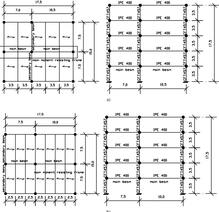
construction phase. All slabs were arranged in parallel to main frames as shown in Fig. 1.
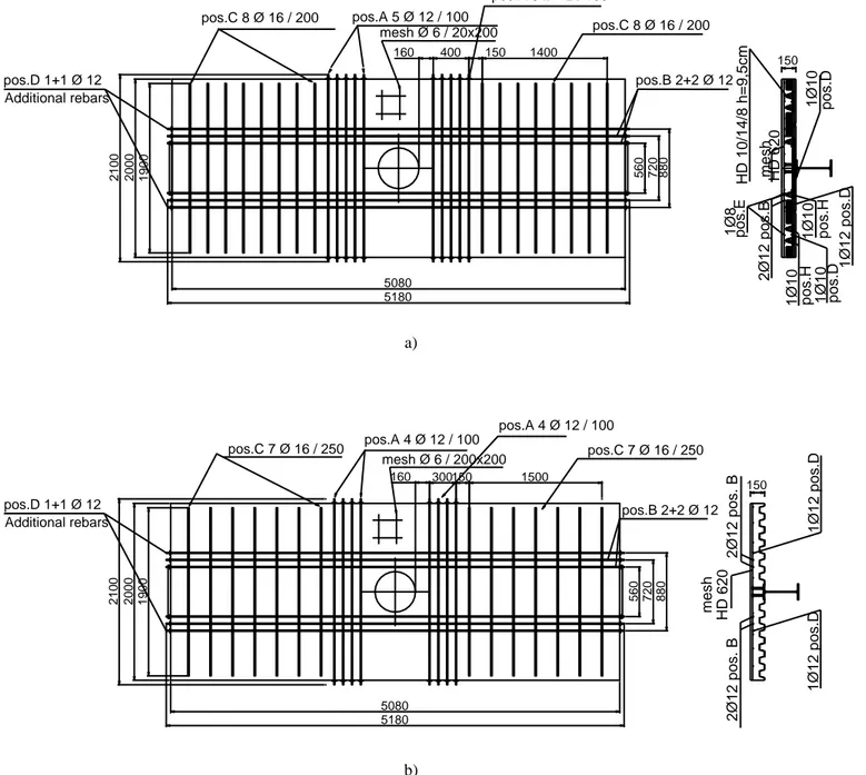
Slabs of reference frames were identical to the slabs used for the test specimens that are indicated in
Fig. 2. In detail, two different types of slab were designed and employed. In the first one, see Fig. 2a,
the deck was a composite slab 150 mm thick with a prefabricated lattice girder with slab
reinforcements provided by 2+2 12 longitudinal steel bars and by 5+5 12 @ 100 mm plus 8+8 16 @ 200 mm transversal steel bars. A mesh 6 @ 200x200 mm completed the slab reinforcement. Two additional longitudinal rebars (1+1 12) were designed to resist seismic damage. In the second type of slab shown in Fig. 2b, a composite slab 150 mm thick with profiled steel sheeting was made with the
same slab reinforcements. The concrete class was C30/37 while the steel grade S450 was adopted for
the reinforcing steel bars. All connections between steel beams and slabs were full strength
connections and were made by Nelson 19 mm stud connectors with an ultimate tensile strength fu=450
MPa. In both cases, composite beams were realized with S355 IPE400 steel profiles and were Class 2,
while composite columns were realized with 457 mm circular steel tubes with 12 mm wall thickness;
column reinforcement consisted of 816 longitudinal steel bars and stirrups 8 @ 150 mm as shown in Fig. 3.
The seismic performance of the frames was evaluated by means of non-linear static and dynamic
analyses. More details on seismic analysis and design can be found in [19].
The corresponding fire design was carried out and the structural fire performance of the complete
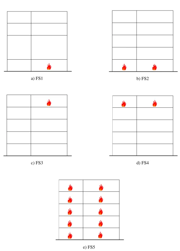
frames was evaluated by means of the SAFIR program [22] for different fire scenarios. In detail, five
fire scenarios were considered as depicted in Fig. 4. In detail, in the first one (FS1), fire acts only into a
both columns and beams of that floor are heated as shown in Fig 4b; in the third one (FS3), fire acts only
into a span of the upper floor as depicted in Fig 4c; in the fourth one (FS4), fire acts on the fifth floor
only, see Fig 4d; in the fifth one (FS5) fire acts on the whole frame as illustrated in Fig 4e. The fire curve
followed the ISO 834 curve [16]. For each scenario all steps were performed, starting from the
determination of the temperature distribution inside all section elements, and ending with structural
analysis carried out to determine frame responses under static and fire loads.
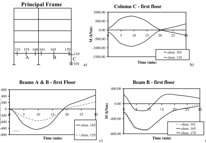
Fig. 5 shows both the evolution of the bending moment and of the axial force as a function of time at
various locations of the frame for the specific case FS1. In detail, the distribution of bending moment
in column C of Fig. 5a depicted in Fig. 5b shows a sign inversion when axial forces in beams change
sign too – see Fig. 5c-. Initially indeed, the increase of temperature causes an increment of axial load
in the beam -compression- up to about 18 min owing to the presence of a column restraint as illustrated
in Fig. 5c. Then, the reduction of stiffness of columns subject to fire prevails and the axial force in the
beam changes to tension, becoming similar to a catenary structure characterized by large deflections.
The elongation of the beam owing to the increase in temperature and the different restraint effects
provided by the columns also cause a sign reversal of the bending moments at mid-span of the beam
which from sagging becomes hogging and then sagging again; see in this respect Fig. 5d. These results
show clearly that the frame approaches collapse because of the formation of a beam mechanism in the
longest span involving the formation of three plastic hinges located at mid-span and at both beam ends,
respectively.
Along the line of Della Corte et al. [5], the effect of the seismic loading applied prior to fire loading
was taken into account by imposing one loading-unloading cycle through identical horizontal forces
applied at each floor. In addition to an initial imperfection, this loading cycle induced some plasticity
in each frame. The impact of the earthquake on the fire resistance of the analysed frames appeared to
be not so significant because failure occurred when a beam plastic mechanism formed in the long-span
2.2 Joint design
The seismic design of composite beam-to-column joints was conceived to provide both adequate
overstrength and stiffness with respect to the connected beams, thus forcing the plastic hinges
formation in adjacent beams. Joints were detailed by using the component method in agreement with
Eurocode 3-1-8 and Eurocode 8-1 [18,2], as shown schematically in Fig. 6, to achieve the necessary
overstrength of the joint with respect to the adjacent composite beams. The following components were
considered in the method: concrete slab in compression; upper horizontal plate in compression; vertical
plate in bending and lower horizontal plate in tension, for a sagging moment; reinforcing bars in tension,
upper horizontal plate in tension; vertical plate in bending and lower horizontal plate in compression for
a hogging moment. Stiffness and strength of complex components, like top and bottom plates or
concrete slab in compression, were defined by means of refined FE models of the joint including friction
between slab and column; accordingly, to activate better the transfer mechanisms in the slabs a solution
with 19 mm Nelson stud connectors welded around the column was adopted [19, 20] as depicted in
Fig.7a. This solution, further verified through FE analysis, enhanced the load transfer based on the
strut and tie mechanism proposed in Eurocode 8-1 [2].
The corresponding solution without Nelson Studs is shown in Fig. 7b. Because plastic hinges were
forced to form in the beams adjacent to each joints, in practice no remarkable difference was recorded
in the response of these two different solutions. Further considerations can be found in [19, 20].
In order to improve the seismic-induced fire behaviour, the joint design foresaw: a welded top collar
plate; a web-through plate; two additional 12 rebars (1+1 12 longitudinal steel bars) to take into account of seismic damage.
The aforementioned components were adopted to predict the moment-rotation-temperature behaviour
of the examined joints in the absence of axial thrust caused by the thermal expansion restraint of
elevated temperature, FE models were employed. Models were subjected to fire loading in agreement
with the ISO 834 curve [16]. In detail, the Abaqus 6.4.1 software [23] was employed to conduct FE
thermal analysis of joints for different times of fire exposure, i.e. ambient temperature, 15, 30 and 60
min, respectively. All components of joints such as columns, beams, slabs and welds were modelled
using eight-node linear brick (DC3D8) elements, while four-node linear tetrahedron (DC3D4)
elements were employed in order to model the transition zones between different meshes.
For instance, Fig. 8a illustrates the case of a slab with profiled steel sheeting where all steel parts
exposed to fire increase their temperature very quickly, reaching a very high temperature after only 15
minutes of exposure. Conversely, both in concrete and in steel components embedded or close to
concrete, i.e. rebars, the horizontal plate close to the slab and the vertical plate passing through the
column, temperature does not increase so quickly, and remains close to ambient temperature. In
addition, after 30 min of fire exposure, joints endowed with prefabricated slabs exhibit a more
favourable thermal behaviour compared to joints endowed with steel sheetings. This performance is
further checked in Subsection 4.2 that deals with fire tests.
3. Test programme
The experimental program consisted of ten seismic tests and six fire tests on full-scale substructures
representing interior and exterior welded steel-concrete composite beam-to-column joints with
concrete filled tubes.
Seismic tests were carried out at the University of Trento and at the University of Pisa, Italy,
respectively, by considering cyclic and monotonic loading [20, 24, 25]. Conversely, fire tests were
conducted at the Building Research Establishment (BRE), UK, with asymmetric loading on joints, in
3.1 Pre-damaged tests
The objective of this experimental program carried out at the BRE, UK consisted in the evaluation of
the fire resistance of joints partly damaged by an earthquake. Therefore to estimate damage,
simulations on the frames introduced in Subsection 2.1 were performed [19]. In a greater detail, four
specimens listed in Table 1, were subjected to an equivalent static loading. Because at the BRE it was
not possible to perform cyclic tests capable to reproduce damage caused by seismic loading, equivalent
vertical forces were applied to virgin specimens in order to produce the same damage. In this respect, a
specific value of monotonic loading was imposed to specimens; each test was terminated when the
load-displacement relationships imposed onto the specimens generated damage values equivalent to
those values reported in the Table 2. Further information about the analysis for damage assessment can
be found both in [20] and in Subsection 4.1.
3.2 Fire tests
A total of six fire tests were carried out and the specimens are listed in Table 3. It can be observed that
FD-IWJ-S1, FD-IWJ-S3, FD-IWJ-P1, and FD-IWJ-P3 were pre-damaged whilst the remaining ones
were not [27]. As stated in the Introduction, the performance criterion for the examined joints entailed
the capability of demonstrating 15 minutes fire resistance once damaged by earthquake effects without
any additional fire protection. This performance requirement was set within the PRECIOUS project
[20].
In agreement with EN 1991-1-2 and EN 1990 [1, 26], the load combination considered for specimens
subjected to fire tests was as follows:
d K j K d G Q A E
, 2,1 ,1 (1) where: dj K
G ,
is the characteristic value of permanent action j;
1 , 2
factor for quasi-permanent value of a variable action assumed equal to 0.3
1 , K
Q is the characteristic value of the accidental load;
d
A is the design value of fire action
In this respect and for the sake of comparison with tests available in the literature, the fire load Ad
followed the ISO 834 Standard Fire Curve (SFC) [16], rather than a natural fire or a parametric curve
[1].
4. Test results
As anticipated above only pre-damaged and fire test results on joints are presented herein. Relevant
seismic test results are reported and commented in depth elsewhere [19, 20].
4.1 Results from pre-damaged tests
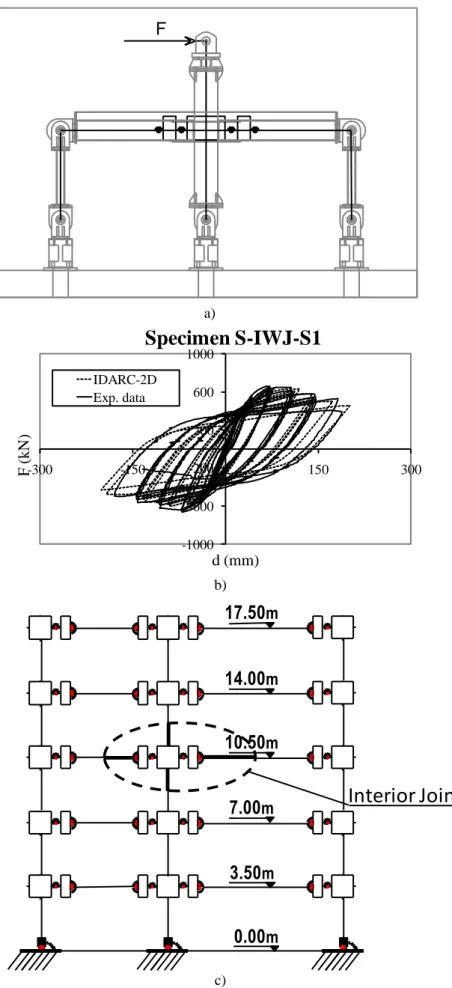
Data obtained from the seismic test program were used to calibrate a joint model, in order to be able
to perform seismic simulations on moment resisting frames. The model used to perform these analyses
is based on two parallel springs at the end of the beam connected to a rigid panel which represents the
rigid connection to the column. Each spring is used to match the properties of the beam under sagging
and hogging bending moment, respectively. Another spring is used to connect this panel with the shear
panel of the column as illustrated in Fig. 9a. The main purpose of this spring was to take into account
the shear deformation of the connection in order to improve the response of the model.
into account the seismic degradation of the joint according to a modification of the Bouc-Wen model
implemented by Silvaselvan-Reinhorn [29] in IDARC-2D. The actual measured properties of both
concrete and steel were used in the model, in order to match as accurately as possible the results of
experimental tests. The quality of calibration can be assessed from Fig. 9b, where experimental data
and numerical prediction with reference to the specimen S-IWJ-S1 are overlapped.
Successively, the frames shown in Fig. 1 were simulated by the model shown in Fig. 9c, in order to
estimate damage owing to strong seismic events. Therefore, non-linear dynamic time history analyses
were performed by using the IDARC-2D program [28] with spectrum compatible accelerograms of
0.4g peak ground acceleration (p.g.a.). In order to estimate the damage level of joints, the Park and
Ang [30] damage index D – that ranges between 0 and 1 – as modified by Chai and Romstad [31] was
considered. It is based on a linear combination of damage owing to excessive deformation and the
surplus of cumulative energy (Eh – Ehm), being Eh the hysteretic total energy at the design strength Pu ,
and the energy Ehm dissipated by the member during a monotonic loading process design strength Pu.
In these conditions, the damage index reads:
um M hm h um y um M E E P D (2) where,
is an empirical factor determined by experimental data;
M
is the maximum response displacement;
um
is the maximum response displacement under a monotonic loading;
y
P is the yield strength.
Relevant values of damage indices reported in Table 2 were not so high for both interior and
exterior joints. Therefore seismic-induced damage can be considered limited and repairable [32].
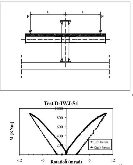
Successively, specific load values were imposed to specimens, see Table 1 in order to simulate the
a typical response is indicated in Fig. 10b. During damage tests, loads, deflections and rotations of the
slab were measured and achieved values are listed in Table 1.
4.2 Results from fire tests
The temperature evolution of 4 sensors G1-G4 located on the composite slab as well as the average
temperature of the furnace -Av. Atmos- together with ISO 834 Standard Fire Curve -SFC- [16] for the
Specimen F-IWJ-S2 endowed with profiled steel sheeting are shown in Fig. 11a. It appears that the
temperature is different depending on the relative position between burner and sensors; in fact
temperature is higher for sensors closer to the burner. The corresponding furnace gas average
temperature evolution and the temperature distribution on composite beams and joints is illustrated in
Fig. 11b and 11c, for East and West beam, respectively. Because the burner is located in the corner
bottom part of the East beam, see Fig. 11b, also in this case, the temperature distribution is not uniform.
In particular, it can be observed that temperatures increase from the bottom flange to the top beam
flange, and temperatures of sensors 11, 10 and 12 of the East beam are higher than the temperatures of
sensors 13, 8 and 9. This distribution is also influenced by the presence of the concrete slab which
mitigates the temperature of the top beam flange. The lowest temperature of the web is also explained
by the fact that it goes through the CFT.
Similar considerations can be made with reference to the temperature distribution measured for the
specimen F-IWJ-P2 endowed with a prefabricated lattice slab and represented in Fig. 12. Nonetheless,
we need to note that east and west views are interchanged in this case.
Fig. 13a shows the test set-up used for fire tests. In detail, it can be observed the furnace zone and
forces applied to beams in order to simulate the accidental load combination defined in Eqn. 1 acting
on beams of unequal length [1].
The temperature vs. time curve imposed to the specimens FD-IWJ-S1 - F-IWJ-S2 and FD-IWJ-P1 -
with profiled steel sheeting slabs exhibited failure owing to an excessive rate of deflection at
approximately 40 minutes. The test on specimen FD-IWJ-S1 terminated after approximately 34
minutes owing to runaway deflection. During the fire test, the profiled steel sheeting separated from
the slab as illustrated in Fig. 14a; then the slab cracked both along the surface and through the depth
with extensive buckling at 40 minutes both of the lower flange and the web of the adjacent east beam
(see Fig. 14).
FD-IWJ-P1 and F-IWJ-P2 specimens endowed with prefabricated slabs endured one hour of fire;
however, in both cases specimens were very close to failure as indicated, in Fig. 13c, by an increasing
rate of deflections towards the end of the test. However, at this stage, there was no permanent
deformation and no sign of any significant damage from fire tests. Hence, it can be underlined that: i)
there was no noticeable difference in the fire performance between pre-damaged and undamaged
specimens both with precast and steel sheeting slabs; this result is in agreement with the damage value
prediction reported in Table 2 and with the inherent safety of composite joints designed for seismic
loading; ii) precast slabs performed better in fire tests than the corresponding specimens with steel
sheeting at a fire exposure in excess of the 15 minutes required; iii) all specimens exhibited favourable
seismic properties by performing in a ductile manner also under fire loading.
5. Conclusions
In this paper both numerical and experimental results of welded steel-concrete composite full strength
beam-to-column joints under post-earthquake fire were described, as part of a European project aimed
at developing fundamental data and prequalification design guidelines of ductile and fire resistant
composite beam-to-column joints with concrete filled tubes.
more favourable behaviour compared to joints endowed with steel sheeting composite slabs. Then,
pre-damaged tests as well as fire experimental tests conducted on undamaged and pre-damaged joints
were presented. Experimental tests confirmed that specimens with precast slabs exhibited lower
deformations for given loads and temperatures. Moreover, experimental results showed that: there was
no noticeable difference in the fire performance between damaged and undamaged specimens both
with precast and steel sheeting slabs owing to the inherent reliability involved in the seismic joint
design with relevant Eurocodes. Precast slabs performed better in fire tests than the corresponding
specimens with steel sheeting at a fire exposure time in excess of the 15 minutes required by design.
Thus, fire tests demonstrated the ability of full strength composite beam-to-concrete filled circular
hollow section joints to survive a damage equivalent to that corresponding to a design seismic event of
0.4 g peak ground acceleration earthquake with a return period of 475 years. Thus, the adequacy of the
concurrent seismic and fire design was proved with full strength ductile joints. Finally, further work is
needed to code in EN 1993-1-2 Section 4.2.5 [7] experimental data and simulation prediction of
temperature distribution of joints.
ACKNOWLEDGMENTS
The writers are grateful to the European Union for financial support under the project
PRECIOUS-RFS-CR-03034 and to the partners, Profilarbed S.A., Ferriere Nord S.P.A., University of
Navarra and University of Pisa. Nonetheless, conclusions of this paper are those of the authors and not
of the sponsoring agency.
[1] EN 1991-1-2. (2004). Eurocode 1: Actions on structures - Part 1-2: General actions - Actions on
structures exposed to fire.
[2] EN 1998-1. (2005). Eurocode 8: Design of structures for earthquake resistance - Part 1: General
rules, seismic actions and rules for buildings.
[3] Sekizawa, A.; Ebihara, M.; Notake, H. (2003). Development of Seismic-Induced Fire Risk
Assessment Method for a Building, Proceedings. Seventh (7th) International Symposium.
IAFSS. June 16-21, Worcester, MA.
[4] Scawthorn, C., Eidinger JM, Schiff AJ., editors Fires Following Earthquake. Technical Council
on Lifeline Earthquake Engineering Monograph, 26, 2005.
[5] Della Corte G., Landolfo R., Mazzolani F.M. (2003). Post-earthquake fire resistance of moment
resisting steel frames, Fire Safety Journal 2003; 38:593-612.
[6] Ding J., Wang Y.C. (2009) Temperatures in unprotected joints between steel beams and
concrete-filled tubular columns in fire; Fire Safety Journal 2009; 44:16-32.
[7] EN 1993-1-2 (2005) Eurocode 3: Design of steel structures - Part 1-2: General rules -Structural
fire design
[8] EN 1994-1-2 (2005) Eurocode 4 - Design of composite steel and concrete structures - Part 1-2:
General rules - Structural fire design.
[9] Al-Jabri K. S., Lennon T., Burgess I. W. and Plank R. J. (1998)."Behaviour of steel and composite
beam-column connections in fire". Journal of Constructional Steel Research, 46: p. 308-309.
[10] Spyrou S., Davison J. B., Burgess I. W. and Plank R. J. (2004). "Experimental and analytical
investigation of the „compression zone‟ component within a steel joint at elevated temperatures". Journal of Constructional Steel Research,. 60(6): p. 841-865.
[11] Spyrou S., Davison J. B., Burgess I. W. and Plank R. J. (2004). "Experimental and analytical
investigation of the „tension zone‟ components within a steel joint at elevated temperatures". Journal of Constructional Steel Research, 60(6): p. 867-896.
[12] Block F. M., Burgess I. W. and Plank J. B. (2004)."Numerical and Analytical Studies of Joint
Component Behaviour in Fire" Third International Workshop on Structures in Fire, (Paper S7-4).
[13] Al-Jabri K. S., Davison J.B., Burgess I.W. (2008). Performance of beam-to-column joints in
fire-A review, Fire Safety Journal 2008; 43:50-62.
[14] Wald F., Simões da Silva L., Moore D.B., Lennond T., Chladnà M., Santiago A., Beneš M. ,
Borges L. (2006). Experimental behaviour of a steel structure under natural fire, Fire Safety
Journal 41 (2006) 509–522.
[15] Dong Y.L., Zhu E.C., Prasad K. (2009). Thermal and structural response of two-storey two-bay
composite steel frames under furnace loading Fire Safety Journal 44 (2009) 439-450.[16] ISO
834-1 (1999). Fire-resistance tests - Elements of building construction -- Part 1: General
requirements.
[16] ISO 834-1 (1999). Fire-resistance tests - Elements of building construction - Part 1: General
requirements.
[17] Wang Y. C. and Davies J. M., (2003). "An experimental study of the fire performance of
non-sway loaded concrete-filled steel tubular column assemblies with extended end plate
connections". Journal of Constructional Steel Research, 59: 819-838.
[18] EN 1993-1-8. (2005). Eurocode 3: Design of steel structures - Part 1-8: Design of joints.
[19] Bursi O. S., Cajot L-G., Ferrario F., Gracia J., Plumier A., Pucinotti R., Salvatore W. (2008).
Seismic performance of welded steel-concrete composite beam-to-column joints with concrete
[20] Bursi O.S., et al. Editors. (2008). Final Report PRECIOUS Project Contr. N. RFSCR-03034.
Prefabricated Composite Beam-to-Concrete Filled Tube or Partially
Reinforced-Concrete-Encased Column Connections for Severe Seismic and Fire Loadings.
[21] Bursi O. S., Ferrario F., Pucinotti R., (2008). Steel-Concrete Composite full strength Joints with
Concrete Filled Tubes: Design and Test Results, 12th International Symposium on Tubular
Structures October 8 to 10, 2008 Shanghai, China.
[22] Franssen J.M. (2005). SAFIR. A Thermal/Structural Program Modelling Structures under Fire,
Franssen J.-M., Engineering Journal, A.I.S.C., Vol 42, No. 3, 143-158.
[23] Hibbitt, Karlsson and Sorensen, (2000). “ABAQUS User‟s manuals”. 1080 Main Street,
Pawtucket, R.I. 02860.
[24] ECCS. 1986. Recommended Testing Procedure for Assessing the Behaviour of Structural Steel
Elements under Cyclic Loads. Publication n° 45.
[25] SAC 1997, Protocol for Fabrication, Inspection, Testing, and Documentation of Beam-Column
Connection Tests and Other Experimental Specimens, report n. SAC /BD-97/02.
[26] EN 1990:2002/A1 (2005). Eurocode - Basis of structural design.
[27] Lennon T., Hopkin D. (2009). Structural Composite Connections for Sequential Seismic and
Fire Performance, Information Paper 02/09, 1-8, Building Research Establishment.
[28] Valles R.E., Reinhorn A.M., Kunnath S.K., Li C., Madan A. (1996). IDARC2D Version 4.0: A
Program for the Inelastic Damage Analysis of Buildings, Tech. Report NCEER-96-0010, 1-8.
[29] Silvaselvan M.V., Reinhorn A.M., (1999). Hysteretic Model for Cyclic Behaviour of
Deteriorating Inelastic Structures, Technical Report MCEER-99-0018;
[30] Park Y. J. and Ang, A. H. S., (1985). Mechanistic Seismic Damage Model for Reinforced
[31] Chai Y. H. and Romstad K. M., (1997). Correlation Between Strain-Based Low-Cycle Fatigue
and Energy-Based Linear Damage Models, Earthquake Spectra, Vol. 13, No. 2, pp. 191-209;
[32] Williams M.S., Sexsmith R.G., (1995), “Seismic Damage Indices for Concrete Structures: A
Table 1: Summary of results for joints under pre-damage loading Specimen label Joint position Max. Est. Load (kN) Max. Deflection (mm) Max. Est. Moment (kNm) Max. Rotation (mrad) D-IWJ-S1 Interior 424 32 887 10.0 D-EWJ-S3 Exterior 258 58 541 7.4 D-IWJ-P1 Interior 425 21 893 7.3 D-EWJ-P3 Exterior 398 110 836 12.6
IWJ-P = Interior Welded Joint with prefabricated slab IWJ-S = Interior Welded Joint with steel sheeting slab EWJ-P = Exterior Welded Joint with prefabricated slab EWJ-S = Exterior Welded Joint with steel sheeting slab
Table 2: Damage index of welded joints Joint position
Joint with steel sheeting slab Joint with prefabricated slab
Interior 0.27 0.42
Exterior 0.31 0.50
Table 3: Joint specimens under fire loading
Specimen label Maximum atmosphere temperature (°C) Maximum steel temperature (°C) Test duration (min) Comments FD-IWJ-S1 1024 747 40
Test terminated due to runaway deflection. Full depth cracking and separation between steel sheet and slab.
F-IWJ-S2 970 966 60 No permanent deformation.
FD-EWJ-S3 972 963 60 No permanent deformation.
FD-IWJ-P1 1196 810 34 Test terminated due to runaway deflection.
Local buckling of the lower flange.
F-IWJ-P2 982 721 45 Test terminated due to runaway deflection.
Cracking and spalling of concrete.
FD-EWJ-P3 944 726 56 Test terminated due to runaway deflection.
Local buckling of the lower flange.
a)
b)
Figure 1: Geometric layout of the reference structures: a) structure with slabs endowed with prefabricated lattice girders; b)
structure with slabs endowed with profiled steel sheeting
150 mesh Ø 6 / 20x200 8 80 5180 2 1 00 pos.B 2+2 Ø 12 7 20 5 60 pos.C 8 Ø 16 / 200 pos.A 5 Ø 12 / 100 400 160 5080 2 0 00 1400 150 pos.A 5 Ø 12 / 100 pos.C 8 Ø 16 / 200 1 9 00 1Ø8 HD 6 2 0 m esh HD 1 0/ 14 /8 h =9 ,5 cm 1Ø10 1Ø10 po s.D po s.H 2Ø12 pos .B po s.E 1Ø10 po s.D 1Ø10 po s.H 1Ø12 pos .D pos.D 1+1 Ø 12 Additional rebars a) 150 mesh Ø 6 / 200x200 880 2100 2000 1900 pos.C 7 Ø 16 / 250 pos.A 4 Ø 12 / 100 5180 pos.B 2+2 Ø 12 720 560 pos.C 7 Ø 16 / 250 pos.A 4 Ø 12 / 100 1500 150 300 160 5080 H D 620 mesh 2Ø12 pos. B pos.D 1+1 Ø 12 Additional rebars 1Ø12 p os.D 1Ø12 p os.D 2Ø12 pos. B b)
pos.D 8 Ø 16 pos.E Ø 8 / 15 cm 95 325 135 50 2490 150 150 150 120 2670 90 40
a) FS1 b) FS2
c) FS3 d) FS4
e) FS5
B C110 101 151 155 160 161 165 170
A
a)
Column C - first floor
-1500.00 -1000.00 -500.00 0.00 500.00 1000.00 0 5 10 15 20 25 30 Time (min) M (kNm) elem. 101 elem. 110 b)
Beams A & B - first Floor
-800 -600 -400 -200 0 200 400 600 0 5 10 15 20 25 30 Time (min) Axia l Load (kN) elem. 165 elem. 155 compressione c)
Beam B - first floor
-800.00 -400.00 0.00 400.00 0 5 10 15 20 25 30 Time (min) M (kNm) elem. 161 elem. 165 elem. 170 d)
Figure 5: Fire Case FS1: Bending moment and Axial load in beams and columns at the first storey
Msd Msd
Msd
Rigid foundation
Concrete and Steel component model
EI=oo
= 300 x 700 x 14 700 300 Web-trough plate 50 19 300 448,4 16 16 369 302 121,5 121,5 CFT Ø 457 x 12 L = 2590 A *1 = 290 x 1250 x 16 A* 5 = 300 x 700 x 14 A *6 R228, 5 1523, 1 4,3 Section D-D 1250 290 80 14 18 D D E E 700 1250 23° 23° 23° 23° 23° 33° 33° Studs 117,6 12 64 30°48 230 60 475 300 475 625 625 1250 40 R231. 5 290 = 290 x 1250 x 16 A* 5B = 290 x 1250 x 16 290 R228, 5 40 1250 625 625 475 300 475 60 230 a=8 L=700 a=8 L=300 a=8 L=700 a=8 L=300 a=8 L=300 A* 5A = 290 x 1250 x 16
with Nelson stud connectors
Top and bottom collar plates Top collar plates
Bottom collar plates
Joint with column Nelson stud connectors a) 1250 700 E E D D 18 14 300 80 60 290 1250 Section D-D 4,3 1523, 1 R228, 5 A 6 = 300 x 700 x 14 A 5 = 290 x 1250 x 16 A 1 CFT Ø 457 x 12 L = 2590 121,5 121,5 302 369 16 16 300 19 50 230 60 475 300 475 625 625 1250 40 R228, 5 290 = 290 x 1250 x 16 A 5A 300 700 = 300 x 700 x 14 A 6 1523, 1 A 5B = 290 x 1250 x 16 290 R231. 5 40 1250 625 625 475 300 475 60 230 48 30° 64 12 a=8 L=700 a=8 L=300 a=8 L=700 a=8 L=300 a=8 L=300 A 5A = 290 x 1250 x 16
without Nelson stud connectors
Web-trough plate Top and bottom collar plates
Top collar plates Bottom collar plates
Joint without column Nelson stud connectors
b)
Figure 7: Beam-to-column Joints; a) solution with Nelson stud connectors in the column; b) solution without Nelson
a)
b)
Figure 8: Abaqus simulations - Distribution of temperature after 30 minutes in a joint endowed with a) a slab with a steel
F a) -1000 -600 -200 200 600 1000 -300F ( -150 0 150 300 k N ) d (mm)
Specimen S-IWJ-S1
IDARC-2D Exp. data b) 0.00m 473 23 6,5 198,25 99,125 99,125 23 6,5457 Baricentro soletta in c.a.
Baricentro ala inferiore IPE400 Bordo esterno colonna
99,125 99,125
Pannello Rigido
Limite zona irrigidita Geometria del Modello del Nodo di Prova Modello del Nodo di Prova
Molla Rotazionale 2 Molle Rotazionali in Parallelo
P a nn ello Ri gid o P a nn ello Ri gid o 473 23 6,5 198,25 99,125 99,125 23 6,5
457 Baricentro soletta in c.a.
Baricentro ala inferiore IPE400 Bordo esterno colonna
99,125 99,125
Pannello Rigido
Limite zona irrigidita Geometria del Modello del Nodo di Prova Modello del Nodo di Prova
Molla Rotazionale 2 Molle Rotazionali in Parallelo
P a nn ello Ri gid o P a nn ello Ri gid o 473 23 6,5 19 8,2 5 99 ,1 25 99 ,1 25 236 ,5 457 Ba rice ntr o s ole tta in c. a. Ba rice ntr o a la in fe rio re IP E4 00 Bo rd o e ste rn o co lo nn a 99 ,1 25 99 ,1 25 Pa nn ello Ri gid o Lim ite zo na ir rig id ita Ge om etri a d el Mo de llo d el No do di Pro va Mo de llo de l No do di Pro va Mo lla R ota zion ale 2 M olle Ro ta zion ali in P ara lle lo P a nn ello Ri gid o P a nn ello Ri gid o 473 236 ,5 198,25 99,125 99,125 236 ,5
457 Baricentro soletta in c.a.
Baricentro ala inferiore IPE400 Bordo esterno colonna
99,125 99,125
Pannello Rigido
Limite zona irrigidita Geometria del Modello del Nodo di Prova Modello del Nodo di Prova
Molla Rotazionale 2 Molle Rotazionali in Parallelo
P an ne llo Ri gid o P an ne llo Ri gid o 473 236 ,5 198,25 99,125 99,125 236 ,5
457 Baricentro soletta in c.a.
Baricentro ala inferiore IPE400 Bordo esterno colonna
99,125 99,125
Pannello Rigido
Limite zona irrigidita Geometria del Modello del Nodo di Prova Modello del Nodo di Prova
Molla Rotazionale 2 Molle Rotazionali in Parallelo
P an ne llo Ri gid o P an ne llo Ri gid o 473 236 ,5 19 8,2 5 99 ,1 25 99 ,1 25 236 ,5 457 Ba rice ntr o s ole tta in c. a. Ba rice ntr o a la in fe rio re IP E4 00 Bo rd o e ste rn o co lo nn a 99 ,1 25 99 ,1 25 Pa nn ello Ri gid o Lim ite zo na ir rig id ita Ge om etri a d el Mo de llo d el No do di Pro va Mo de llo de l No do di Pro va Mo lla R ota zion ale 2 M olle Ro ta zion ali in P ara lle lo P an ne llo Ri gid o P an ne llo Ri gid o 473 2 36,5 198,25 99,125 99,125 23 6,5
457 Baricentro soletta in c.a.
Baricentro ala inferiore IPE400 Bordo esterno colonna
99,125 99,125
Pannello Rigido
Limite zona irrigidita Geometria del Modello del Nodo di Prova Modello del Nodo di Prova
Molla Rotazionale 2 Molle Rotazionali in Parallelo
Pa nn ello Ri g id o Pa nn ello Ri g id o 473 2 36,5 198,25 99,125 99,125 23 6,5
457 Baricentro soletta in c.a.
Baricentro ala inferiore IPE400 Bordo esterno colonna
99,125 99,125
Pannello Rigido
Limite zona irrigidita Geometria del Modello del Nodo di Prova Modello del Nodo di Prova
Molla Rotazionale 2 Molle Rotazionali in Parallelo
Pa nn ello Ri g id o Pa nn ello Ri g id o 473 2 36,5 19 8,2 5 99 ,1 25 99 ,1 25 23 6,5 457 Ba rice ntr o s ole tta in c. a. Ba rice ntr o a la in fe rio re IP E4 00 Bo rd o e ste rn o co lo nn a 99 ,1 25 99 ,1 25 Pa nn ello Ri gid o Lim ite zo na ir rig id ita Ge om etri a d el Mo de llo d el No do di Pro va Mo de llo de l No do di Pro va Mo lla R ota zion ale 2 M olle Ro ta zion ali in P ara lle lo Pa nn ello Ri g id o Pa nn ello Ri g id o 473 236 ,5 198,25 99,125 99,125 23 6,5
457 Baricentro soletta in c.a.
Baricentro ala inferiore IPE400 Bordo esterno colonna 99,125 99,125
Pannello Rigido
Limite zona irrigidita Geometria del Modello del Nodo di Prova Modello del Nodo di Prova
Molla Rotazionale 2 Molle Rotazionali in Parallelo
P an ne llo Ri gid o P an ne llo Ri gid o 473 236 ,5 198,25 99,125 99,125 23 6,5
457 Baricentro soletta in c.a.
Baricentro ala inferiore IPE400 Bordo esterno colonna 99,125 99,125
Pannello Rigido
Limite zona irrigidita Geometria del Modello del Nodo di Prova Modello del Nodo di Prova
Molla Rotazionale 2 Molle Rotazionali in Parallelo
P an ne llo Ri gid o P an ne llo Ri gid o 473 23 6,5 19 8,2 5 99 ,1 25 99 ,1 25 236 ,5 457 Ba rice ntr o s ole tta in c. a. Ba rice ntr o a la in fe rio re IP E4 00 Bo rd o e ste rn o co lo nn a 99 ,1 25 99 ,1 25 Pa nn ello Ri gid o Lim ite zo na ir rig id ita Ge om etri a d el Mo de llo d el No do di Pro va Mo de llo de l No do di Pro va Mo lla R ota zion ale 2 M olle Ro ta zion ali in P ara lle lo P a nne llo Ri gid o P a nne llo Ri gid o 473 2 36,5 198,25 99,125 99,125 236 ,5
457 Baricentro soletta in c.a.
Baricentro ala inferiore IPE400 Bordo esterno colonna 99,125 99,125
Pannello Rigido
Limite zona irrigidita Geometria del Modello del Nodo di Prova Modello del Nodo di Prova
Molla Rotazionale 2 Molle Rotazionali in Parallelo
P a nn ell o Ri g id o P a nn ello Ri g id o 473 2 36,5 198,25 99,125 99,125 236 ,5
457 Baricentro soletta in c.a.
Baricentro ala inferiore IPE400 Bordo esterno colonna 99,125 99,125
Pannello Rigido
Limite zona irrigidita Geometria del Modello del Nodo di Prova Modello del Nodo di Prova
Molla Rotazionale 2 Molle Rotazionali in Parallelo
P a nn ell o Ri g id o P a nn ello Ri g id o 473 236 ,5 19 8,2 5 99 ,1 25 99 ,1 25 2 36,5 457 Ba rice ntr o s ole tta in c. a. Ba rice ntr o a la in fe rio re IP E4 00 Bo rd o e ste rn o co lo nn a 99 ,1 25 99 ,1 25 Pa nn ello Ri gid o Lim ite zo na ir rig id ita Ge om etri a d el Mo de llo d el No do di Pro va Mo de llo de l No do di Pro va Mo lla R ota zion ale 2 M olle Ro ta zion ali in P ara lle lo P an nello Ri g id o P an ne llo Ri g id o 3.50m 7.00m 10.50m 14.00m 17.50m
Interior Joint
c)Figure 9: a) FE model of an interior composite joint; b) comparison between experimental and simulated data for the
F F L L a) 0 200 400 600 800 1000 -12 -6 0 6 12 M [ KNm ] Rotation (mrad) Test D-IWJ-S1 Left beam Right beam b)
Figure 10: Pre-damaged tests of Interior Joints endowed with a steel sheeting slab; a) Load introduction; b)
0 200 400 600 800 1000 1200 0 20 40 60 80 100
T
em
p
.
[°
C]
Time [Min]
Specimen F-IWJ-S2
G3 G4 G1 G2 SFC Av. Atmos Burner G1 G2 G3 G4 a) 0 200 400 600 800 1000 0 20 40 60 80 100T
em
p
.
[°
C]
Time [Min]
(East beam)Specimen F-IWJ-S2
TC7 TC8 TC9 TC10 TC11 TC12 TC13 Av. Atmos SFC 12 9 8 7 13 10 11 b) 0 200 400 600 800 1000 0 20 40 60 80 100 T em p ( °C)Time [Min] (West beam)
Specimen F-IWJ-S2
TC21 TC22 TC23 TC24 TC25 TC26 TC27 Av. Atmos SFC 26 23 22 21 27 24 25 c)Figure 11: Undamaged Interior Joint, F-IWJ-S2, endowed with a steel sheeting slab; a) temperature distribution in the top
0 200 400 600 800 1000 1200 0 20 40 60 80 100 T em p . [ °C] Time [Min]
Specimen F-IWJ-P2
G1 G2 G3 G4 SFC Av. Atmos Burner G1 G2 G3 G4 a) 0 200 400 600 800 1000 0 20 40 60 80 100 120T
e
m
p
.
[°
C]
Time [Min]
(East Beam)Specimen F-IWJ-P2
TC21 TC22 TC23 TC24 TC25 TC26 TC27 av. atmos SFC 26 23 22 21 27 24 25 b) 0 200 400 600 800 1000 0 20 40 60 80 100 120 T em p ( °C)Time (Min)
(West beam)Specimen F-IWJ-P2
TC7 TC8 TC9 TC10 TC11 TC12 TC13 Average Atmos SFC 12 9 8 7 13 10 11 c)Figure 12: Undamaged Interior Joint, F-IWJ-P2, endowed with prefabricated slab; a) temperature distribution in the top
part of the furnace; b) temperature distribution in the East Beam; c) temperature distribution in the West Beam
F1=140kN F2=70kN L L Furnace zone a) -900 -450 0 450 900 -75 -50 -25 0 25 50 75 15 30 45 60 75 90
V
er
ti
ca
l
D
ef
le
ct
io
n
[
m
m
]
Time [min]
FD-IWJ-S1 vs. F-IWJ-S2
F-IWJ-S2:East Deflection F-IWJ-S2: West Deflection FD-IWJ-S1:West Deflection FD-IWJ-S1: East Deflection F-IWJ-S2:Temperature FD-IWJ-S1:TemperatureT
e
m
p
.
[
C]
b)-900
-450
0
450
900
-75
-50
-25
0
25
50
75
15
30
45
60
75
90
V
er
ti
cal
D
ef
le
ct
io
n
[m
m
]
Time [min]
FD-IWJ-P1 vs. F-IWJ-P2
F-IWJ-P2:West Deflection F-IWJ-P2:East Deflection FD-IWJ-P1:West eflection FD-IWJ-P1:East Deflection F-IWJ-P2:Temperature FD-IWJ-P1:TemperatureT
e
m
p
.
[
C]
c)Figure 13: a) load introduction in the specimen; b) comparison between pre-damaged (FD-IWJ-S1) and undamaged
(F-IWJ-S2) steel sheeting specimens; c) comparison between pre-damaged (FD-IWJ-P1) and undamaged (F-IWJ-P2) precast specimens
a) b)
c) d)
Figure 14: Fire test of a pre-damaged interior joint endowed with a steel sheeting slab; a) concrete cracking and steel