Any correspondence concerning this service should be sent to the repository administrator: [email protected]
This is an author’s version published in: http://oatao.univ-toulouse.fr/22451
Official URL
DOI : https://doi.org/10.1007/978-3-030-00247-3_16 Open Archive Toulouse Archive Ouverte
OATAO is an open access repository that collects the work of Toulouse researchers and makes it freely available over the web where possible
To cite this version: Gonzalez, Nicolas and Van Den Bossche, Adrien and Val, Thierry Specificities of the LoRa physical layer for
the development of new ad hoc MAC layers. (2018) In: 17th
International Conference on Ad Hoc Networks and Wireless (AdHoc-Now 2018), 5 September 2018 - 7 September 2018 (St Malo, France).
Specificities of the LoRa
™ Physical Layer
for the Development of New Ad Hoc
MAC Layers
Nicolas Gonzalez1,2(B), Adrien Van Den Bossche2, and Thierry Val2
1 Snootlab SAS, 10 Boulevard d’Arcole, 31000 Toulouse, France
2 Institut de Recherche en Informatique de Toulouse, Universit´e de Toulouse,
UT2J, Blagnac, France
{nicolas.gonzalez,vandenbo,val}@irit.fr
Abstract. The Internet of Things and particularly energy constraint object revealed these last years some radio frequencies technologies which allow to realize wireless transmissions at long range and with low energy. This change of paradigm makes tip over the problems of multi-hop net-works to multi-channel MAC netnet-works. The LoRa™ technology arises from this sphere of influence by using the spread spectrum to reach the expected performances. This physical layer is very original compared with the physical layers used for a long time with the IEEE 802.15.4 standard. This article highlights the specificities of the LoRa™ physical layer to design new MAC layers for the ad hoc Internet of Things.
1
Introduction
The Internet of Things (IoT) is a growing field. This is a relatively large area of application where many scientific, technological and societal issues arise. Techno-logically, IoT can be addressed by the data side or by the network side. Regarding the network part, we distinguish the collection network, wireless and energy con-strained, from the rest of the backbone constraints and challenges are not the same. It is considered that the wireless part of the IoT (Device-Layer of the IoT [1]) inherits ad hoc mobile networks (MANET) and wireless sensor net-works (WSN) from the proximity of constraints and latches [2]. However, recent technological advances in narrow-band (NB) and ultra-narrow-band (UNB) tech-nologies are opening up new possibilities, such as radio range, topologies, and multi-channel access. These possibilities make it possible to consider new col-lection network, especially at the MAC level. This is for example the case with LoRa™ technology, the acronym for “Long Range” which is a NB wireless trans-mission technology for long range and energy efficient transmissions for the node sensors. Thanks to its various parameters, LoRa™ makes it possible to imagine new medium access controls. This article proposes to list the different technical levers that the LoRa™ radio physical layer offers and to study the performances
_
outside any MAC consideration. This study shows the beginnings of the devel-opment of new MAC layers for the Internet of Things.
This article is structured as follows: after this introduction, we present in more detail the problematic of the transition from multi-hop to multi-channel. Next, we present a detailed analysis of the LoRa™ technology and the different levers that it allows to activate, particularly in terms of the isolation of logical channels, followed by a state of the art of the techniques for using these methods. Then we present an experimental study evaluating, on a real test bench, the logical isolation capacity offered by LoRa™. In a final part, we present ways to improve MAC mechanisms in LoRa™, before concluding the article.
2
Problem: From Multi-hop to Multi-channel
For many years, in the dynamics of the IEEE 802.15.4 standard, a major diffi-culty in scaling up the number of nodes is at the routing level. The very limited resources in terms of datarate, computational performances and energy of the nodes of this type of network do not make it possible to search and find routes efficiently on a large number of nodes of the global network. The IEEE 802.15.4 standard, heavily used in recent years, mainly uses physical layers that have a fairly high throughput for a sensor network (250 kbit/s) but whose range is limited (200 to 300 m in outdoor and 30 m in indoor ).
The use of physical layers like LoRa™ makes it possible to greatly increase the radio range, which has the effect of changing the type of topology, protocol architecture and therefore globally, paradigm [3]. It is interesting to note that for the usual applications of the Internet of Things, with an equal node density, for a LoRa™ network, the density of the links increases and the distance in number of jumps decreases, compared to a network 802.15.4. The Fig.1 makes it possible to represent this change of scale at the level of the radiofrequency cells. This last point makes it possible to release the constraints on the layer 3 and on the multi-hops routing algorithms. However, this constraint is transferred to the MAC layer because with the increasing density, a larger number of nodes must share the medium on the same local geographical area. This disadvantage is accentuated by a longer transmission time, which collapses the capacity of the medium.
It is necessary, at the MAC level, to take advantage of the possibility of instantiating several channels in order to distribute the nodes on all the available channels and to find suitable temporal performances, thus making it possible to scale up.
3
Analysis of the Levers Offered by LoRa
™
LoRa™ is a narrow-band wireless transmission technology, which gives it a high degree of robustness (high receiver sensitivity, long range). The trade-off that needs to be made is at fairly low throughput. There is also a limitation of the emission duty cycle (duty cycle) related to the fact that the LoRa™ modulation is intended for ISM bands (Industry, Scientific and Medical) which are unlicensed bands. These bands are said to be unlicensed because they can be used by any user without a license, which favors the uncoordinated deployment of varied and generally incompatible networks. This is an essential detail in our reflection because the use of these bands can be very strong and they can be very polluted and electromagnetically congested.
LoRa™ technology is based on CSS (Chirp Spread Spectrum) which is a par-ticular spread spectrum technique. The goal of the CSS techniques is to spread the spectrum on different frequencies and on different instant of the time by adding both a strong redundancy and a correlation in the signal in order to greatly increase the robustness thus limiting the multipath phenomena. This modulation is obtained by coding the information using orthogonal codes, quan-tified by the Spreading Factor (SF). In the next section, the different parameters of the LoRa™ physical layer are presented.
3.1 LoRa™ Physical Layer Settings
Spreading Factor. In order to increase the reliability of the transmission and thus make it possible to send messages at long range, the LoRa™ modulation uses a strong redundancy of information. For this, each bit of the message is coded by a symbol composed of several bits. In this way, it is much more difficult to confuse a ‘1’ or a ‘0’ received. This increases the signal-to-noise ratio, which makes it possible to reach objects in harsh environments or at longer distances. The SF simply corresponds to the number of “bits” per symbol. The Table1 shows the different spreading factors currently available in LoRa™ tranceivers. A Chirp is a frequency sweep used by CSS to represent a bit at the physical level. The number of Chirp/symbol represents the number of symbols at the physical level to represent a bit of information. This metric gives us the number of symbols used to represent a bit of information, so this is the coding efficiency at the physical level. For each SF, there are two codes, one for the ‘0’ symbol and one for the ‘1’ symbol. Note that the more the SF increases, the longer the code length is and therefore the lower the useful bit rate is. When we increase the SF by 1, we multiply the length of the code by 2 and thus we divide the data rate by 2. According to the Friis formula (1), one can deduce that a gain of 6 dB on
the link budget makes it possible to double the transmission range. For example, moving from a SF 7 to a SF 12, improves the coding gain of +12.5 dB. This gain makes it possible to have a transmission distance multiplied by four. The Friis model is a simple model that is not adapted to a Smart City environment but we use it here to just give an idea of the impact of the spreading factor.
Table 1. Range of spreading factors from datasheet [4]
SpreadingFactor 6 7 8 9 10 11 12
Chirps/symbol 64 128 256 512 1024 2048 4096
LoRa™ Demodulator SNR −5 dB −7.5 dB −10 dB −12.5 dB −15 dB −17.5 dB −20 dB
P r = P t + Gt + Gr − 32.45 − 20 × log(f req) − 20 × log(rang) (1) Pt : Emission power
Pr : Reception power
Gt : Gain of the reception antenna
Gr : Gain of the emitter antenna freq : Emission frequency in MHz rang : Range in km
An important property of the SF is that the codes used are orthogonal to each other from a mathematical point of view. That is, from a theoretical point of view, a message coded with a certain SF can not influence a message with another SF present at the same time on the same medium, in the same place. We are in the presence of several logical channels, even if they are on the same frequencies. Of course, the LoRa™ modulation requires that the receiver and the transmitter are parameterized with the same SF to be able to communicate together. It is very interesting to note that in the current LoRa™ radios, there is a technological difference between an end-device and a gateway. A gateway is able to receive messages with different Spreading Factors without having to reconfigure its radio. This property allows it to have a privileged place in the network, however, it is still bound to the same legislation as the End-Devices. Coding Rate. The LoRa™ modulation natively uses cyclic redundancy codes, of the Hamming code type, which make it possible to check the integrity of the message received. This check is performed after receiving a message to the correct SF. The tranceiver automatically recalculates the cyclic code and depending on the result decides whether or not to validate the received message. In the header of the physical layer, there is a field that indicates the coding rate of the message. This allows a receiver to receive messages with different coding rates. On the other hand, the coding rate does not make it possible to create new channels unlike the SF! The array Table2 shows the different possible coding rate values in a LoRa™ tranceiver.
Table 2. Set of coding rate from datasheeet [4] Cyclic coding rate 4/5 4/6 4/7 4/8 Overhead ratio 1.25 1.50 1.75 2
Bandwidth. Bandwidth (BW) is the bandwidth used during a transmission. It is expressed in Hertz. For the modulation LoRa™, it is possible to send a chirp per second and per Hertz of bandwidth. That is, if you select a bandwidth of 500 kHz, you will be able to send 500000 chirps per second. Depending on the SF and the Coding Rate that we have chosen, we will be able to determine the maximum possible data rate. According to [5], the division of the value of BW by two makes it possible to gain 3 dB of additional sensitivity. According to the formula Friis (1), a 125 kHz emission instead of 500 kHz allows to gain 6 dB and thus to double the transmission range in free field.
3.2 LoRa™ Logical Channels
In our problem of densification of nodes in radio range, it is necessary to make the best use of the available parameters in order to create a multitude of subsets of communication channels that do not interfere with each other. Here in after, we briefly present the frequency and time division techniques that have already been used. In a second step, we will present the creation of channels by coding using the SF.
Channels by Frequency Division. It is currently possible to use LoRa™ directly in the 433 MHz, 868 MHz and 2.4 GHz bands due to the availability of associated transceivers on the market. For example, the SX1276, the SX1272 and the RN2483A. Take for example the 868 MHz band in Europe that is used by the LoRaWAN protocol. LoRaWAN is a MAC and network protocol based on a LoRa™ physical layer. This band ranges from 868.0 MHz to 868.6 MHz with a radiated power limit of +14 dBm, a duty cycle of less than 1% and no limit on bandwidth [6]. Therefore, it is possible to divide this 600 kHz band into several frequency channels. This is what was decided for the LoRaWAN protocol with the use of three main channels at 868.10 MHz, 868.30 MHz and 868.50 MHz center frequencies. On these bands, it was chosen to use a bandwidth of 125 kHz, which leaves a width of 75 kHz between the channels. We see that it is possible to go much further in the cutting of this band, using channels with different bandwidths for example.
Channels by Time Division. As with other radio technologies, it is possible to set up a time multiplexing of transmissions. The specificity, however, is that currently, LoRa™ is used on the so-called ‘ISM’ bands and that the limitation of these unlicensed bands obliges an emitter to respect the duty cycle limitation
at 1% maximum. This imposes a cumulative total issue time of 36 s maximum over a rolling hour. The limitation on the transmission time is 3.6 s and 1.8 s between two transmissions. With a relatively standard setting (SF7, 125 kbps) a frame of 30 bytes lasts 70 ms on the medium. With the legal limitation, it is possible to send 514 messages per hour. This limitation on the duty cycle is not applicable if the MAC layer implements a Listen Before Talk (LBT) mechanism, i.e. an analysis of the free or busy medium before sending. The effect of LBT is similar to that of Clear Channel Assessment (CCA) used in CSMA/CA type MAC protocols but not based on an energy threshold.
Channels by Coding. Coding multiplexing is the most original and interesting for the LoRa™ physical layer. Indeed, the use of SF will allow to create a third dimension of channels. As the codes used by the different Spreading Factors are orthogonal, it is possible to perform simultaneous transmissions on the same medium air while avoiding collisions. It is conceivable to think that, as there are 7 spreading factors (from 6 to 12), the number of channels available by time and/or frequency multiplexing is multiplied by 7. It should be noted that the SF 6 is a bit special because it requires the use of the implicit mode which is a payload transmission mode of fixed size. However the choice of a SF is not insignificant! The first remark is the emission time that evolves at power 2 according to the SF. At the same time, the robustness of the signal is improving! We will therefore be able in a given frequency channel to create several channels depending on the state of the link. A transmitter that is very far from the receiver or in adverse conditions will be able to change SF to pass on a more robust channel, and better radio range.
Synthesis. The use of LoRa™, in unlicensed bands today, allows via different techniques to make many logical channels. It must be remembered that despite all the use of unlicensed bands imposes a limitation of the duty cycle which is in no way solved by multi-channel MAC techniques. The coding channels are very original and interesting in the LoRa™ technology because they allow very different channels in terms of range and robustness. This diversity of channel parameters could be used to setup the physical layer according to the range between two nodes.
An important parameter for MAC layer development is the impact of syn-chronization on performance. Indeed, the logical tightness between the chan-nels must not be dependent on the temporal phase shifts between the chanchan-nels because it is a very difficult problem to solve.
4
Related Works
The most deployed MAC layer based on a LoRa™ physical layer is LoRaWAN. This MAC layer already uses datarate adaptation mechanisms, by changing SF and transmission power, in order to optimize communications [7]. It is the device
(connected sensor) and not the central base station, which can choose to auto-matically adapt its parameters or ask the network to determine them. LoRaWAN therefore already uses a SF pluralism mechanism but only for the purpose of opti-mizing static devices. This is not enough because the goal for LoRaWAN is to optimize the objects independently and not to distribute them intelligently in channels.
The joint optimization strategy of the transmission power and SF is justified by [9] because changing SF is much less optimal from an energy point of view than increasing the transmission power. The strategy to optimize the robustness of the links is to increase the transmission power to a point where it is more optimal to change the SF and reduce the transmission power.
In addition to this justification [9] shows that the optimization of energy can only be done by a strict spatial re-use by using the orthogonality property of the spreading factors.
According to [10] routing algorithms like RPL are difficult to use in a LPWAN context on unlicensed bands. The strict legislation in terms of number of mes-sages does not leave much space for algorithms requiring frames dedicated to the operation of the network. It is necessary to design new MAC layers that counterbalance these routing issues.
In order to design these MAC layers, it is important to carry out a rigorous theoretical and practical study of the isolation between the spreading factors and the influence on the properties of an associated MAC layer. Several articles have treated the theory as [11], we propose to complete this study by experiments in real environment.
5
Performance Analysis of Logical Isolation Between
Spreading Factors
5.1 Experience with Time Phase Collisions
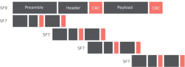
Experimental Protocol. In order to prove the hypotheses advanced, we set up an experiment with 4 nodes, two transmitters and two receivers of End-Device type (Adafruit Feather [13] with HopeRF RFM95 transceiver [14]). We seek to study the impact of a simultaneous emission of two nodes on the same frequency band but with different spreading factors. The choice to use four nodes makes it possible to group them in pairs with the same parameters, one node in transmission and the other in reception. By analyzing the received frames and what they contain, we can deduce the frame error rate (FER) and compare it with the same rate without simultaneous emissions. The synchronization of the nodes is very important to finely control the phase shifts between the two transmitting nodes. Thanks to this synchronization, we can select a large frame and a small frame to analyze if the rate varies according to the crush zone of the packet. In order to achieve this synchronization, we connected the two transmitters by two wires and two Boolean signals. Figure3 shows the wiring of this synchronization. One node is master and the other slave, the master waits
Fig. 2. Synchronization of transmitters by wire
for the first signal of the slave which indicates to him that he is ready to emit. Once the master is ready to transmit and has received the signal from the slave, it sends a signal to the slave to tell him to start transmitting the frame (Fig.2). When the SF is increased by 1, the size of the packet is approximately dou-bled. We chose to use one package with a SF of 9 and another of 7. The packet sizes are respectively 250 ms and 70 ms. These sizes make it possible to take the longest packet as a reference and to crush it (disrupt it or collide it) by shifts by the second. This experiment was carried out in these realistic conditions that is to say that the two transmitters were side by side in one side and the two receivers on the other side. The two couples are separated from a distance of 200 m with a building in between. The distance of 200 m seems weak but given the indoor conditions of the nodes, we noticed by the practice, that we were in limit of reach for the link to SF7 which is the least robust. We have observed in practice and it is explained in [8] that in the near field there are orthogonality problems between SF. We decided not to do the measurements in this topology which is not representative of reality.
Fig. 3. Simultaneous transmission of frames at the same frequency but with different spreading factors
Results. The experiment consists of sending 500 frames for a fixed time offset between the frame at SF 9 and that at 7. We decided to send 500 packets in order to have a correct estimate of the frame error rate. We have selected these values for the time offset so as to test crashes (overlaps or collisions) on different parts of the packet. This proves that this overwriting property is valid on all parts of the packet (Table3).
Analyse. The frame error rate is very low and uniform whatever the area of the packet, this allows us to demonstrate that it is possible to send several frames simultaneously at the same frequency, with the same parameters but with a different SF. This physical isolation makes it possible to assert that it is
Table 3. Estimate of FER on an emission of 500 frames per measurement point. Delay 2 frames ok SF9 frame ok SF7 frame ok FER
0 ms 494 0 6 0.012
77 ms 489 0 11 0.022
154 ms 475 0 25 0.05
231 ms 490 0 10 0.02
possible to create physical channels on the same frequency that have different characteristics in terms of reliability and throughput. This physical isolation is not dependent on a time synchronization between the different channels and is not dependent on the content of the frame.
5.2 Collision Matrix on All Spreading Factors
Experimental Protocol. After proving that for a given pair of spreading factors (7 and 9), there is a real tightness at the physical channel level, it is necessary to generalize this property. For this, we place ourselves in the same experimental conditions, with two transmitters synchronized by logic signals, and two non-synchronized receivers. We will build a collision matrix. For this we parameterize a transmitter/receiver pair with a SF1 SF and the other pair with SF2. Then under these conditions, we re-test all possible time offsets.
Results. Table4 is an example of a result for a delay of 10 ms between the two transmitters. The numbers are very similar regardless of the delay, so showing only one sample is enough.
Table 4. Spreading factor matrix for 10 ms delay
sf1 7 7 7 7 8 8 8 8 9 9 9 9 10 10 10 10 sf2 7 8 9 10 7 8 9 10 7 8 9 10 7 8 9 10 ok 0 500 488 497 497 0 484 500 489 489 37 489 487 491 495 8 1 ok 49 0 12 3 3 18 16 0 11 11 6 11 13 9 5 16 error 205 0 0 0 0 449 0 0 0 0 456 0 0 0 0 474 nok 246 0 0 0 0 33 0 0 0 0 1 0 0 0 0 2
Analyse. For the diagonal of the matrix of the array Table4, when the two emitters use the same SF, we notice that there are many collisions. We can not conclude that there is a tightness when two transmitters speak simultaneously with the same SF. When the two nodes emit with different SFs, the number of collisions is limited. It can happen, with a rate of 2.2%, that one of the two messages is not received by the receiver.
6
Towards New Ad Hoc MAC Layers for the Internet of
Things
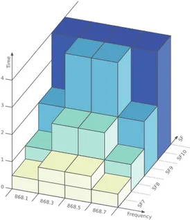
The results presented in this paper show that the LoRa™ physical layer proposes several levers that make it possible to envisage new MAC protocols that benefit from the characteristics of this mode of transmission. In view of what has been described above, we propose a new concept of 3-dimensional MAC layer, using the three frequency, time and code multiplexing, illustrated by the Fig.4.
Fig. 4. Channel multiplexing on the time, frequencies and by code
The first two multiplexes (frequency, time) are relatively conventional, they are used by most technologies. Frequentially, the selected band, for example the 868 MHz ISM band, can be subdivided into frequency channels with a fixed (as in LoRaWAN) or variable bandwidth, in order to better use the properties of the LoRa™ modulation. In this case, higher bandwidths will allow links with higher throughput for short-range communications. On the second (temporal) multiplexing, we have seen in the experiments that the othogonality of the links does not depend a priori on a strict synchronization. However, it is necessary to synchronize the nodes constrained in energy; the Listen Before Talk tech-nique can help limit temporal collisions. On these two first multiplexings, we are finally in a standard case of multi-channel MAC where it is possible to apply the algorithms of this domain (with or without an appointment, with or without a dedicated channel, etc.). What the LoRa™ technology allows to add, is that for a given channel {frequency, temporal}, a communication can be realized via a SF whose value will have an impact on the robustness and the range of the link. In addition, SF being orthogonal, several links between several objects can be made at the same time on the same channel {frequency, temporal}. The object can, for example, start with a low value of SF and attempt a communication
with the target gateway. If he can not reach his recipient, after several tries, he can increment his SF and retry to connect. Once the connection is established, the gateway can record the parameters of the transmission in order to respond to the transmitter with the same parameters. The transmission will be more and more robust until you succeed. In this way, a node will be able to adapt its transmission technique to the quality of the link and/or its distance. The Fig.4 represents this type of 3-dimensional multi-channel MAC. The different colors represent the SF used by a sending node. During the initialization phase of a node and dynamically during its lifetime, the node is colored according to the state of the link between it and the gateway. If the link is degraded, the node will change its settings and change color to a darker color.
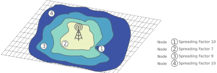
Fig. 5.Topology of a multi spreading factor MAC (Color figure online)
In the Fig.5 one observes an example of topology of a MAC multi SF. It is interesting to see that depending on the zone in which it is, the node will have a different SF setting. The node number 4 is very far, it uses a high SF like the node number 1. By cons this node number 1 is much closer in terms of distance. It must surely be in a difficult environment (deep indoor, behind an obstacle between him and the gateway for example...). These solutions are made possible by the fact that a gateway has the possibility of receiving several SF without having to change configuration. This is generally not the case for End Devices, which, for ad-hoc communications between objects, requires to think of another strategy. These few solutions are to be developed later, but have been made possible by the metrology phase that we have just presented.
7
Conclusion
The LoRa™ technology may seem very close to the usual modulations of the IEEE 802.15.4 historical standard, but because of its intrinsic parameters and its context of use, it must lead to rethink the MAC and network layers to much higher topologies star or mesh with two hops. The context of the Internet of Things and LoRa™ defines transmissions in a very dense environment as trans-mission distances are high. This paper permit to define the main mecanisms which can be exploited in order to answer the problem of distribution of nodes in well disjoined channels.
This preliminary work opens the way for many perspectives, such as to pro-pose an original and efficient MAC layer for IoT. In order to overcome the constraints related to the duty cycle imposed by the standardization, it lacks a final tool to define concerning the detection of occupancy of the channel as that used in the well-known CSMA/CA. LoRa™ uses a type of modulation that allows transmissions above the noise level. The RSSI measure is no longer a valid indicator of channel occupancy. The LoRa™ tranceivers integrate a so-called CAD (Channel Activity Detection) mechanism which makes it possible to detect a coherent preamble, the preamble of a message with the same SF. We are currently working to propose a MAC called CSMA/CAD without temporal constraint linked to a duty cycle.
References
1. Khan, R., Khan, S.U., Zaheer, R., Khan, S.: Future internet: the Internet of Things architecture, possible applications and key challenges. In: 2012 10th International Conference on Frontiers of Information Technology, Islamabad, pp. 257–260 (2012) 2. Bellavista, P., Cardone, G., Corradi, A., Foschini, L.: Convergence of MANET and
WSN in IoT urban scenarios. IEEE Sens. J. 13(10), 3558–3567 (2013)
3. Pham, C.: QoS for long-range wireless sensors under duty-cycle regulations with shared activity time usage. ACM Trans. Sens. Netw. 12, 33 (2016)
4. Semtech: Datasheet of Semtech sx1276 LoRa™ tranceiver. http://www.semtech. com/images/datasheet/sx1276 77 78 79.pdf
5. Augustin, A., Yi, J., Clausen, T., Townsley, W.M.: A study of LoRa™: long range & low power networks for the Internet of Things. Sensors 16, 1466 (2016)
6. CEPT ECC: ERC Recommendation 70–03, Relating to the use of Short Range Devices (SRD), 19 May 2017
7. LoRa™ Alliance: LoRaWAN Specification V1.1 (2017)
8. Croce, D., Gucciardo, M., Mangione, S., Santaromita, G., Tinnirello, I.: Impact of LoRa imperfect orthogonality: analysis of link-level performance. IEEE Commun. Lett. 22(4), 796–799 (2018)
9. Ochoa, M.N., Guizar, A., Maman, M., Duda, A.: Evaluating LoRa energy efficiency for adaptive networks: from star to mesh topologies. In: IEEE 13th International Conference on Wireless and Mobile Computing, Networking and Communications (WiMob) (2017)
10. Sartori, B, Bezunartea, M., Thielemans, S., Braeken, A., Steenhaut, K.: Enabling RPL multihop communications based on LoRa. In: IEEE 13th International Con-ference on Wireless and Mobile Computing, Networking and Communications (WiMob) (2017)
11. Lim, J.T., Han, Y.: Spreading factor allocation for massive connectivity in LoRa systems. IEEE Commun. Lett. 22(4), 800–803 (2018)
12. Cheong, P.S., Bergs, J., Hawinkel, C., Famaey, J.: Comparison of LoRaWAN classes and their power consumption. In: IEEE Symposium on Communications and Vehic-ular Technology (SCVT) (2017)
13. Adafruit: Feather Hardware. https://www.adafruit.com/feather 14. HopeRF: The HopeRF RFM95 Transceiver User Manual