• Aucun résultat trouvé

DEVELOPMENT OF A NEW APPROACH TO INCREASE THE ELECTRICAL PERFORMANCE OF ANODIC ASSEMBLIES

N/A
N/A
Protected

Academic year: 2021

Partager "DEVELOPMENT OF A NEW APPROACH TO INCREASE THE ELECTRICAL PERFORMANCE OF ANODIC ASSEMBLIES"

Copied!
6
0
0

Texte intégral

(1)

DEVELOPMENT OF A NEW APPROACH TO INCREASE THE ELECTRICAL PERFORMANCE OF ANODIC ASSEMBLIES

Simon-Olivier Tremblay

1

, Daniel Marceau

1

, Duygu Kocaefe

1

, Charles-Luc Lagacé

2

1

University Research Centre on Aluminium (CURAL) - Aluminium Research Centre (REGAL) - University of Québec at Chicoutimi; 555, Boul. de l’Université, Chicoutimi (Québec), Canada, G7H 2B1

2

Aluminerie Alouette Inc.; 400, Chemin de la Pointe-Noire, P.O. Box 1650, Canada, G4R 5M9 Keywords: Anode Voltage Drop, Contact Resistance, Contact Pressure, Anode assembly

Abstract

The electrical resistance of an electrolytic cell requires a voltage drop of about 4.5 V for a current of 300 kA of which 7% is attributable to the anode assembly. Reducing this voltage drop is one of the most challenging research topics for the aluminum industry. Over the past decades, there has been much research on the minimization of this loss using the same assembly configuration. In this work, a new approach, which consists of inserting elements into the carbon paste during the anode production, was developed. This approach would provide a significant reduction in the voltage drop mainly through the improvement of contact quality and contact surface at the anode connection. Laboratory tests simulating the baking as well as the installation steps of small-scale assembly were carried out to estimate the resistance. The results demonstrate that it is possible to decrease the resistance at the anode connection under the conditions similar to those used by industry.

Introduction

The aluminum production requires a considerable amount of electrical energy to supply the necessary electrons to the process.

The electrical resistance of an electrolysis cell involves a potential loss of about 4.5 V. 1.18 V is theoretically necessary for the reduction reaction. The remaining 2.7 V is mainly associated with the resistance of the electrolyte, electrodes (anode and cathode assemblies) and conductors [1]. Among these components, the anode assembly itself represents a loss of about 300 mV. It is believed that there is a promising potential to improve the electrical performance of the cells by optimising the anode assembly design.

As shown in Fig. 1, the anode assembly used in the Hall-Héroult process consist of a carbon anode (1) into which steel stubs (2) are inserted. The stubs are joined together by a steel crossbar (3) which is then connected to an aluminum rod (4) using a clad (5).

To fix the stub to the carbon block, molten iron is cast in the preformed stub holes creating the connector or thimble (6). This assembly mechanically supports the anode and conducts heat and current to the carbon block.

Problem Statement

In a conventional design (see Fig. 2), a cylindrical stub is inserted into a slightly conical stub hole. Once the cast iron solidifies, a gap forms at the cast iron to carbon interface since the carbon is not wetted well by the cast iron. This gap is partially filled during operation due to expansion of cast iron at high temperature.

The shrinkage of the cast iron is greater in the upper portion of the interface than the lower part. The extent of the difference depends on the cast iron thickness, composition and casting conditions. In operation, the contact is initiated at the lower part of the interface since the residual gap is smaller and the temperature is higher in this position. Consequently, the non-

uniformity of the gap at the interface as well as the variable radial expansion of the metal portion result in a partial contact at the cast iron to carbon interface. Since the shrinkage is dependent on the cooling rate, it is difficult to fully control the resulting residual gap. Also, almost no current flows through the circular bottom of the stub due to lack of contact pressure [3]. These factors lead to an additional electrical resistance, thus a higher production cost.

Fig. 1- Anode assembly [2] Fig.2 - Stub to anode connection [3]

Finally, the extreme conditions of the process can cause large changes in the geometry of the connection leading to an additional energy loss [4]. It is important to consider that the manufacture, operation, maintenance and cleaning of the assembly represent a significant portion of the aluminum production costs [5].

The objective of the project is to develop a new anode assembly design in order to minimize the cost related energy loss and rodding operations. The development of a new design includes following four steps:

 Conceptual study;

 Interrelation of key parameters;

 Proposal of a new design;

 Evaluation of the electrical performance of anode assembly.

Previous work Stub to carbon resistance

In 1976, using in situ measurements, Peterson [1] has estimated that 7% of the total voltage drop is due to the anode assembly, out of which 25% attributed to the stub to carbon (STC) connections.

Consequently, the thickness of the cast iron between the stub and the carbon has a direct impact on the STC resistance.

In 1984, Brooks and Bullough [6] demonstrated that the electrical

contact resistance (ECR) is a function of temperature and contact

pressure. This dependence is then quantified in 1985 for a

carbon/steel interface by Rhedey and Castonguay [7]. Fig. 3

shows the original results of Molenarr et al. [2] demonstrating

three distinctive regions of the contact resistance variation.

(2)

In 1996 Hiltmann et al. [8] used an experimental set-up to quantify the ECR between iron and carbon and the results essentially indicated the same trends.

In 2007, Wilkening and Côté [3] has done in situ measurement which showed that there is a voltage drop of approximately 120 mV between the stub and the carbon for a current of about 2400 A/stub. They also used a small bench-scale set-up to measure the STC resistance isothermally for different stub diameters and cast- iron thicknesses. They concluded from these tests that:

- in the lower temperature range up to about 600°C, the contact resistances increases with thickness of the cast iron sleeves due to the higher shrinkage of the thicker cast iron layers;

- the contraction of steel and cast iron at the α to γ phase transition visibly increases the contact resistance (see Fig. 4 and 5).

Fig. 3 - Chart of contact resistance relationships with overlay of original data [2]

Fig. 4 - Effect of steel and cast iron shrinkage in the range of α-

γ phase transition on the STC resistance [3]

Fig. 5. Thermal expansion of new mild steel [3]

In the same publication, Wilkening and Côté [3] presented the thermo mechanical and thermo electrical properties of

components as a function of temperature in the stub-anode connection zone between 550°C and 950°C.

In 2013, Jeddi et al. [9] presented a thermo-electro-mechanical (TEM) anode model calibrated with experimental results. The results show that the real (or effective) contact area is essentially in the lower portion of the contact zone and represents only 42%

and 70% of the nominal contact at 700°C and 950°C, respectively.

Geometry modifications

In the eighties, Brooks and Bullough [6] and Peterson [10] have suggested a design chart for cylindrical connectors. They propose different cast iron thicknesses for selected stub diameters to optimize the contact pressure with the objective of preventing anode cracking.

In 2001, the results of Richard et al. [11] showed that adding more flutes or increasing their length to maximize the nominal contact surface increases the voltage drop compared to that of the original design. In 2009, Richard et al [12] developed a coupled thermal-electrical-mechanical model which led to the same conclusion regarding the addition of flutes. These results show that, in some cases, the voltage drop increases even with a higher nominal contact surface. Therefore, the real contact area (via contact pressure) has to be taken in to account when determining the electrical performance.

In 2009, Li et al. [13] used a thermo electric (TE) model to study the impact of increasing the stub diameter and the number of stubs of an industrial scale anode assuming a constant ECR on the cast iron/carbon interfaces. They concluded that these two elements decrease significantly the voltage drop by maximizing the contact area and improving the uniformity of the current distribution in the anode. However, greater number of stubs requires a longer crossbar, consequently, the thermal expansion of the longer crossbar and the larger diameter of stub significantly increase the stress in the carbon bloc. This might result in anode cracking during operation. The increased frequency of anode cracking increases operational problems as well as manual work requirement.

In the same year, Fortin et al. [14] built a fully coupled TEM model showing that the longitudinal crossbar dilatation generates significant stress on the outer stub hole (thus uneven contact pressure), therefore, creates a toe-in effect of the crossbar as shown in Fig. 6. This element leads to a premature maintenance of the anode assembly.

Fig. 6 – Toe-In effect amplified by a factor of 30 [3]

In 2013, Molenaar et al. [4] used a high amperage testing facility to study the impact of deterioration parameters including the change of stub diameter, height and the eccentricity of the stub in the stub hole on anode performance. He concluded that a net increase of more than 50 mV is possible for a deteriorated anode rod fleet.

Patents

(3)

In 1986, Friedli et al. [15] proposed to attach the carbon block to the studs or spades using an adhesive mass which is mechanically strong and a good electrical conductor. It was recommended that studs or spades are inserted in the cold-poured adhesive and vibrated until they come to rest on the bottom of the anode holes.

The anode assembly is then stored until the adhesive mass has at least partly hardened. This approach allows connexion to the carbon block without using cast iron, thus, possibly provides a better contact between the studs or spades independent of the geometry (at least after insertion). Considering the relation shown in Fig. 3, it is possible that the adhesive mass does not allow an effective contact pressure buildup during operation due to its low stiffness.

In 2002, Tsomaev [16] proposed to slide a large rectangular head of metal into a preformed slot in the carbon block (see Fig. 7). It was claimed that this configuration will improve the mechanical and electrical contact with by increasing the contact area between the head and the carbon block and eliminating the need for cast iron. The approach allows possibly a more uniform current distribution in the anode and a better control of the electrical contact resistance because of the absence of residual gap and free expansion of the head in longitudinal direction. However, it is possible that, after repeated anode cycles, the geometrical changes induced in the bar due to extreme conditions of the process might possibly deform the preformed slot of the carbon leading to a higher electrical resistance.

Fig. 7 – Anode assembly proposed by Tsomaev [16]

In 2012, Fafard et al. [17] proposed to connect the carbon block to a longitudinal bar using a pourable conductive material such as cast iron (see Fig. 8). Different cross section shapes of the bar and the rectangular stub hole are also proposed (plane IV in Fig.

8). This approach allows a reduction in energy loss due to a larger contact surface and a better distribution of the current in the anode. However, if the cooling rate of the pouring material is not controlled precisely during sealing, it is possible that the non-the uniform gap at the cast iron/carbon interface might decrease the contact area after solidification.

Fig. 8 – Anode assembly proposed by Fafard et al. [17]

Conceptual study

To propose an optimal design, it is essential to identify the key parameters previously found which lead to an improvement of the electrical performance and the reduction of the cost related rodding operations.

Resistance at the connector/carbone interface

The resistance at the connector/carbon interface is dependant of:

 the ECR;

 the nominal contact surface for a given ECR;

 the distribution of the real contact area at the interface;

Fig. 3 shows that, for a given temperature, the minimum ECR is achieved with a contact pressure of 10 Mpa. However, it is known that an excessive contact pressure might create a significant stress in the carbon block leading to cracking in anode. Finally, another crucial element is to maximize the nominal contact surface considering a given ECR.

Since the operational temperatures in the anode connection zone is between 550°C and 950°, the ideal situation would be to obtain a minimum ECR (corresponding to 10 Mpa) on the entire nominal contact surface at 550°C and maintain this electrical performance up to 950°C. Thus, the thermal expansion of the connector should be minimized after 550°C in order to avoid the damage to the carbon block. However, to obtain significant contact pressures at 550°C on the entire nominal contact surface with a low thermal expansion of the connector, the gap at the connector/carbon interface must be minimal and uniform before the operation.

Resistance of the carbon block

Li et al. [13] showed that a significant improvement can be attained by increasing the number of stubs which leads to improvement of the current distribution in the anode. This means that uniform current distribution at the top surface of the anode would allow the current to travel along a vertical path directly to the base of the carbon block (thus a shorter path) leading to a lower resistance.

Resistance of the crossbar

This is mostly affected by the cross sectional area of the crossbar (cutting plane perpendicular to current lines) and the material resistivity itself. Evidently, the cross section area of the crossbar has to be maximized in order to be able to uniformly distribute the current to the stubs.

Maintenance and rodding operations

Decreasing the number of parts and modifying their geometries might decrease significantly the cost of the maintenance and the rodding operations of the anode assembly.

Interrelation of key parameters

A conceptual study has identified the key parameters, factors

affecting them and the elements that can be adjusted to optimize

these parameters. Fig. 9 presents a diagram of the interrelation of

the key parameters which are taken into consideration for

developing the new anode assembly. The red boxes indicate TEM

key parameters whereas the green boxes give TE key parameters.

(4)

Fig. 9 – Interrelation of key parameters

It is also essential to consider the economic aspects related to the manufacture, operation, maintenance (degradation) and cleaning of the assembly.

Development of the new anode assembly

The next step is to determine, using Fig. 9, the adjustable elements that optimize the key parameters via their dependant factors considering the industrial practice.

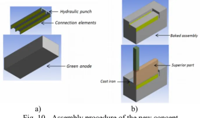
The proposed approach is to introduce multiple thin rectangular steel connection elements to the anode during the forming step (Fig. 10a). After baking, cast iron is poured between the crossbar and connection elements to allow the current to travel from the crossbar to the connector elements (Fig. 10b) and also to support the anode via a preformed groove (not shown in Fig. 10). In this configuration, the side surfaces of the connection elements distribute the current to the anode block.

a) b)

Fig. 10 - Assembly procedure of the new concept Assumptions concerning the TE key parameters

The larger nominal contact surface and the more uniform current distribution of the new concept will significantly reduce the total resistance of the anode assembly compared to that of the actual assembly used in industry.

Assumptions concerning the TEM key parameters

The proposed procedure of assembly is based on the fact that the densification of the anode during the baking process leads to possibly to a larger contraction than that caused by the cooling of the steel connection elements after the baking process. Also, the low expansion of the thin connection elements proposed in the

new design will not cause any damage to the carbon anode during the baking process. Finally, considering the two previous assumptions, the approach would allow a low ECR for a range of thicknesses of the connection elements. This will accordingly result in a robust electrical performance through the anode cycles.

Industrial practice advantages and disadvantages The advantages of the new design can be listed as follows:

 the modified crossbar will prolong the anode lifetime due to the larger cross-sectional area compared to the stubs of the actual design;

 the maintenance of the crossbar is less costly considering the three welds between the stubs and the crossbar of the actual design;

 the modified crossbar and the connection elements can expand freely in their longitudinal direction avoiding the creation of significant stress in the anode and the crossbar;

 the cleaning of the bath is easier considering the simple geometry;

 possibly it will result in a more uniform carbon density around the connection in the anode.

On the other hand, some disadvantages are also identified such as:

 makes the vibro-compaction operation more complex;

 requires an important modification in the rodding processes.

Evaluation of the electrical performance

The potential of the new concept is evaluated using two different methods. Firstly, the TE key parameters are estimated using a true scale representation of the new concept and the actual design in a thermo electrical model. Secondly, the TEM key parameters are quantified using laboratory tests simulating the baking as well as the installation steps of small-scale assembly.

Evaluation of the TE key parameters

As shown in Table 1, the true scale representations of both designs allow, on a comparative basis, the estimation of the possible electrical gain due to modification of the TE key parameters assuming:

 the ECR for the two designs is constant on the entire nominal contact surfaces;

 for the actual design, the nominal contact surfaces correspond only to the circumferential contact of the three stubs;

 for the new design, the nominal contact surfaces correspond only to the side surfaces of the three rectangular connector elements;

 all the other surfaces in contact with the carbon are insulated;

 the same boundary conditions were used for both;

 only the geometry between the clad and the bottom of the stub hole has been modified (130mm deep).

Table 1 - Impact of TE key parameters on voltage drop.

Nominal contact

surface[mm

2

] 249 945 528 000

Voltage drop: Clad to anode

base [mV] 306 mV 226 mV

(5)

Considering the assumption presented above, a fictitious gain of 80 mV is obtained by improving:

 the cross-sectional area between the clad and the top surface of the anode (31 mV);

 the nominal surface and current distribution (49 mV).

Evaluation of the TEM key parameters

The assumptions made previously will be taken in to account in the evaluation of following TEM key parameters:

 Electrical contact interface;

 Increase of the resistivity of the carbon due to cracking;

 Distribution of real contact area.

To quantify and analyse the TEM key parameters, laboratory tests and microscopic observations are used.

First, to simulate the baking process with the new concept, the green anode samples including the inserted steel connection element are baked in a furnace using the industrial heating rate.

Once baked, a small-scale set-up using a current source of 4A and a furnace is used to provide the voltage drop between the steel connection element and the carbon in an isotherm environment.

By selecting the right performance indicators, it is possible to evaluate the TEM key parameters.

Performance indicators

The experimental results of Wilkening and Côté [3] at isothermal condition (Fig. 4) show that the electrical performance is highly correlated with the thermo mechanical behavior of the stub (Fig.

5). Since the thermal expansion is related to the generation of the contact pressure at the interface and the contact pressure is related to the ECR (Fig. 2), this correlation allows us to identify several elements as performance indicators to quantify the STC resistance using the experimental results.

Fig. 4 shows that there is an asymptotic trend at a lower temperature when the cast iron thickness is smaller. This trend suggests that the contact pressures are optimal (region 'C' of Fig.

3) since the additional thermal expansion of the metal portion does not reduce the STC resistance. This indicates that, after generation of significant contact pressure, the carbon can support an additional expansion of the metal portion without any considerable impact on the electrical performance.

This result is also supported by the fact that the three configurations showing an asymptotic trend at a lower temperature (100/8, 100/10 and 100/12) show a smaller variation in their resistance at the α to γ phase transition (causing a contraction) compared to two other configurations (100/15 and 100/17). Thus, according to Fig. 4, a decrease of the contact pressures initially located in region C has a lower impact on the ECR than if these pressures were initially in region B.

Considering the strong correlations between the variation of the coefficient of thermal expansion (CTE) and the voltage drop tendency, the evaluation and analysis of the TEM key parameters pointed to the following performance indicators:

1) a small increase in voltage drop at the α to γ phase transition of steel means high contact pressure at 750°C at the steel connector element/carbon interface;

2) an asymptotic tendency of the voltage drop before 750°C means an ECR close to the minimum;

3) the amplitude of the voltage drop obtained between the steel connection element and the carbon;

4) a high voltage drop at low temperature means a larger residual gap.

Considering the same correlation, it is possible to link a damaged carbon block to the following crack indicators.

1) an increase in the voltage drop before the α to γ phase transition of steel;

2) a decrease in voltage drop during the α to γ phase transition of steel;

Finally, measurement of the gap after baking at the steel connector element/carbon interface and crack observations for different connector thicknesses can lead to a better understanding of the obtained voltage drop.

Results and discussion Nomenclature:

Here is the nomenclature used to define the different tested sample. Note that the initial gap was not the same for the rectangular sample considering the lack of precision when machining a slot in a green anode.

<Geometry>_< Diameter or thickness [mm]>_<Initial Gap>_<Baked or not>

* <+> means a larger gap before baking;

* <-> means larger initial contact pressure before baking.

Experimental validation

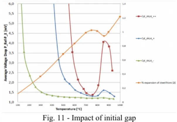
Before testing the TEM performance parameters, simple configurations where a steel cylinder is placed in a baked carbon stub hole with different residual gaps were tested to make sure that the experimental measurements followed the performance indicators.

Fig. 11 - Impact of initial gap

Fig. 11 demonstrates that the experiment procedure is accurate enough to be able to use the performance indicators.

To evaluate the impact of the increase in voltage drop due to carbon cracking, samples with high initial contact pressure have been tested.

Fig. 12 shows the sample of Cyl_44.4_---_2 after the test. Note that Cyl_44.4_---_1 has also two visible cracks.

Fig. 12 - Cracked carbon of tested Cyl_44.4_---_2

(6)

Fig. 13 - Impact of cracked carbon

Fig. 13 shows that cracking of the carbon block can increase the voltage drop before the contraction of the steel. Also, the damaged carbon does not reduce significantly the voltage drop for a small dilatation and the contraction of the steel at the phase change decrease the voltage drop. However, a small increase of the voltage drop during the phase change doesn’t indicate that the carbon remains intact considering that cracks has been observed on Cyl_44.4_-.

Baked assemblies

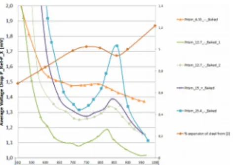
Fig. 14 shows the effect of thicknesses of connectors that have been baked on the voltage drop. The results at room temperature show that, for similar initial gap, thicker is the connector, lower the initial contact pressure will be. Observations also show that the samples with the thickness of 12.7 mm and 6.35 mm are practically joined to the carbon block and it was not easy to take them out manually from the slot.

Fig. 14 shows a zoom-in of Fig. 14 to analyse the behaviour of the interface for different thicknesses at higher temperatures.

Fig. 14 - Impact of thickness connector at high temperature A thinner connector seems to be beneficial since ECR was low at the beginning of operational temperature and the small dilatation afterwards kept the ECR low. Also, the results of the sample Prism_6 35_--_Baked indicated that carbon anode was cracked because of the decrease of ECR during the phase change of steel.

Considering the variation of the mechanical behavior of the carbon, it is important to mention that more tests are necessary to to validate the results.

Conclusions

For a same ECR at the connector/carbon interface, the new design gives significantly lower voltage drop compared to that of the conventional design by improving the nominal contact and the

cross sectional area between the clad and the top surface of the anode.

Also, the experimental results show that the baking process of a connector/carbon assembly can reduce the residual gap at the interface and even generate contact pressure.

Finally, a very low ECR can be achieved with the new approach for a certain range of thickness considering the corresponding performance indicators.

Future work

- Verify the repeatability of the experiments;

- Observations and measurements of the dimensions of the tested samples;

- Determine the evolution of the electrical performance with respect to aging of the insertion elements considering its reuse in the anode assembly;

- Determine the suitable geometry of the mechanical support and the location of the outer insertion elements;

- Determine the electrical gain of the final prototype in comparison to the actual AP30 anode assembly.

Acknowledgement

The author aknowledge the financial support of the Fonds québécois de la recherche sur la nature et les technologies trough the Aluminum Center – REGAL, Nature Sciences and Engineering Research Council of Canada (NSERC) and particularly our industrial partners Aluminerie Alouette Inc.

References

1. R.W. Peterson, “Temperature and voltage measurement in Hall-Héroult cell anodes”, TMS Light Metals 1976, pp. 365- 382.

2. D. Molenaar, K. Ding and A. Kapoor, “Development of Industrial Benchmark Finite Element Analysis Model to study Energy Efficient Electrical Connections for Primary Aluminium Smelters” TMS Light Metals 2011, pp. 985- 990.

3. S. Wilkening and J. Côté, “Problem of the stub-anode connection”, TMS Light Metals 2007, pp.865-873.

4. D. Molenaar, “Experimental investigation of factors affecting the electrical performance of the stub to carbon connection”, TMS Light Metals 2013, pp. 1359-1364.

5. D. Molenaar and B.A. Sadler, “Anode rodding basics”, TMS Light Metals 2014, pp. 1263-1268.

6. D.G. Brooks and V.L Bullough, “Factors in the design of reduction cell anodes”, TMS Light Metals 1984, pp. 961- 976.

7. P. Rhedey and L. Castonguay, “Effects of Carbonaceous Rodding Mix Formulation on Steel-Carbon Contact Resistance”, TMS Light Metals 1985, pp. 1089-1105.

8. F. Hiltmann, J. Mittag, A. Støre and H.A. Øye, “Influence of temperature and contact pressure between cast iron and cathode carbon on contact resistance”, TMS Light Metals 1996, pp. 277-283.

9. E. Jeddi, D. Marceau, L, Kiss and L. St-Georges,

“Experimental and numerical investigation of voltage dropin anode assemblies”, TMS Light Metals 2013, pp.

1347-1352.

(7)

10. R.W. Peterson, M.D. Ohlswager & G.E. Goeres, 1989.

“Anode cast iron thickness optimization”, TMS Light Metals, pp. 499-503.

11. D. Richard., M. Fafard, R. Lacroix, P. Cléry, & Y. Maltais, 2001. “Aluminum reduction cell anode stub hole design using weakly coupled thermo-electro-mechanical finite element models”. Finite Elements in Analysis & Design, 37 (4), 287–304.

12. Daniel Richard, Patrice Goulet, Olivier Trempe, Marc Dupuis and Mario Fafard, “Challenges in stub hole optimisation of cast iron rodded anodes”, TMS Light Metals 2009, pp. 1067-1072.

13. Wangxing Li, Jieming Zhou, Yiwen Zhou, “Numerical analysis of the anode voltage drop of a reduction cell”, TMS Light Metals 2009, pp. 1169-1171.

14. H. Fortin, M. Fafard, N. Kandev, and P. Goulet, “FEM analysis of voltage drop in the anode assembly”, TMS Light Metals 2009, pp. 1055-1060.

15. Hans Friedli and Edwin Gut, U.S. Patent 4574019, 1986.

16. Tsomae, Zelimkhan, S., Internation Patent WO 02/055761 A1, 2002.

17. Fafard, Mario et al, Internation Patent WO 2012/100340A1 A1, 2012.

18. R. W. Peterson, “Studies of stub to carbon voltage”, TMS

Light Metals 1978, pp. 367-378.

Figure

Fig. 1- Anode assembly [2]    Fig.2 - Stub to anode connection [3]
Fig. 3 - Chart of contact resistance relationships with overlay of original data [2]
Fig. 7 – Anode assembly proposed by Tsomaev [16]
Fig. 10 - Assembly procedure of the new concept  Assumptions concerning the TE key parameters
+3

Références

Documents relatifs

where q(Xi) is the wave function of the collective motion depending on the collective variables in the system connected with the main nucleus axes. @( ... F,

In the present paper, we try to overcome the shortcomings associated with the use of multiple bibliometric measures by proposing a procedure to evaluate a global

The influence of the geographic situation on the performances of the PV pumping, we have calculated the characteristic parameters of the system such as: the energy losses and

In contrast, the photoemissive yield was practically insensitive to this extra increase of the surface area and even tended’to decrease (cf. Inter- pretation of

The use of our new cost function has allowed to increase the performances of the pre-network as compared to the standard mean squared error : the false alarm is reduced by 20 % (on

As well, work will begin this year to revamp the provincial physician recruitment strategy to ensure your government can recruit and retain the physicians needed to provide

At position B, the horizontal component of the surface tension force becomes zero, but the liquid inertia and the energy minimisation of the system induces the decrease of

Once two entities are known to be aligned, the nature of the relation between them can be charac- terized using the following mapping types: exact, the connected vertices