OATAO is an open access repository that collects the work of Toulouse
researchers and makes it freely available over the web where possible
Any correspondence concerning this service should be sent
to the repository administrator: [email protected]
This is an author’s version published in: http://oatao.univ-toulouse.fr/20818
To cite this version:
Touhami, Sarah and Lefèvre, Yvan and Llibre, Jean-François
Joint Design of Halbach. Segmented Array and Distributed
Stator Winding. (2018) In: 2018 XXIII International
Conference on Electrical Machines (ICEM), 3-6 September
2018 (Alexandropuli, Greece)
ΦAbstract – In the past, designers develop analytical models that are useful to size rapidly surface mounted permanent magnet synchronous motor with sinusoidal waves and a high specific power. In order to ensure the assumptions of sinusoidal waves, a joint design of the stator winding and the rotor is presented. First, an Halbach permanent magnet array is optimized to obtain the desired airgap magnetic flux density wave. Then, in order to obtain a surface current density wave consistent with the desired wave, the conductor distribution along the stator bore is determined.
Index Terms-- Surface Mounted Permanent Magnet
Synchronous Machine, Halbach magnet array, Conductor distribution functions.
I. INTRODUCTION
NCREASING specific power of electric machines becomes a crucial issue in the hybrid or electric propulsion systems. To rationalize the search of high specific power electric motor, it is helpful to use the loadability concepts defined by some designers [1]. They can characterize intrinsically the performances and the technological levels of electric motors [2]. These concepts and the works presented in [3] can be used to develop analytical models for sizing electrical motors.
One of the advantages of these simple analytical models is that they need very few data: stator and rotor are not described in details. But they need some assumptions. For instance, the models developed in [3] are valid specifically for surface mounted permanent magnet synchronous motor (SM-PMSM) with sinusoidal waves. So the more the motor under designed is close to these assumptions the more the performances of the motor are assessed.
The primary objective of this paper is to develop methods that help to design motors that are very close to the assumptions on which sizing models are based. To reach this goal, a joint design of airgap magnetic flux density and surface current density waves on the stator bore of SM-PMSM sized with Slemon’s models is proposed [2][3][4].
In order to have a radial airgap flux density sinewave, segmented Halbach arrays are investigated. Then an approach based on the conductor distribution functions [5] [6], instead of the classical winding functions [7], is used to design the winding. The goal is to produce a surface current density wave consistent with the magnetic flux density wave.
This project has received funding from the European Union’s Horizon 2020 (Cleansky 2JTI) research and innovation program, 2014-2024 under grant agreement No 715483.
S. Touhami, Y. Lefèvre and J.F. Llibre are with "Laboratoire Plasma et Conversion d’Energie" (LAPLACE), University of Toulouse, CNRS, 31000, Toulouse, France (email: {stouhami,yvan.lefevre,[email protected]})
A first part is devoted to the fundamental waves in sinewave synchronous motor. This part explains why the joint design can be interesting from the point of view of torque productions and justify the use of the conductor distribution functions. It presents also the studied motor sized for a mechanical power of 0.9MW with a high specific power. A second part is devoted to the optimization of a multi-segmented Halbach array in order to generate a sinewave of an airgap radial magnetic flux density. Some works on the optimization of Halbach arrays are recalled in order to underline the main contributions of this paper. A third focuses on conductor distribution functions for the design part of the winding. The last part shows the validation of the proposed approach by 2D finite element analysis.
II. PROPOSED APPROACH
A. Fundamental waves in SM-PMSM
An ideal sinewave synchronous motor is characterized by two fundamental waves on the stator bore. The first fundamental wave is the radial magnetic flux density due to the rotor magnetic sources:
( )
θ t 2B(
pΩt pθ)
B , = rmscos − (1)
Where: p is the number of pole pairs, Ω is the rotor speed, Brms is the rms value of the wave, t is the time and θ is the
angular position along the stator bore.
The second fundamental wave is the axial surface current density due to stator currents:
( )
θ t = 2 K(
pΩt− pθ −α)
K , rmscos (2)
The two waves are in synchronism and the electric angular displacement between them is α. Applying Lorentz and the action-reaction laws, the torque applied on the rotor is given by the surface integral performed on the stator bore Sb:
( )
t S r B( ) ( )
θ,t K θ,t d dz T b 2 θ
= (3)From (1) and (2), this integral leads to the well-known constant torque of non-salient pole synchronous motor:
( )
α π r lB K cos 2T = 2 rms rms (4)
Where: r is the stator bore radius, l is the active length. (1) to (4) show that the surface current density and the airgap flux density waves have to be tuned together in order to obtained the maximal torque (α = 0). Equation (4) defines the well-known load concept namely the tangential stress [1]:
( )
α
σ
tan = BrmsKrmscos (5)Joint Design of Halbach Segmented Array and
Distributed Stator Winding
S. Touhami, Y. Lefevre, J. F. Llibre
B. The origins of conductor distribution functions
In order to model analytically the magnetic field produced by the winding in slotless permanent magnet motor, a surface current density distribution is defined [8]. This distribution is used in boundary condition equations of magnetic scalar potential based in a 2D model. A volume current density is introduced to model the reaction field in permanent magnet motor, in magnetic vector potential 2D model [9][10]. To enlighten the role of the winding and the currents, a surface current density wave K(θ,t) is defined by the separation of space functions and time functions [5][6]:
( )
t C( ) ( )
I t K k q 1 k k θ θ
= = , (6)The space functions are the q phase conductor distributions along the stator bore Ck(θ). The time functions
are the q phase currents Ik(t). If the currents are sinusoidal, to
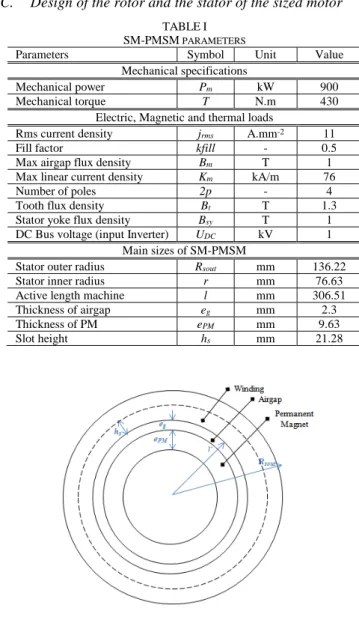
have sinewave surface current density, it is sufficient, but not easy, to have sinusoidal conductor distribution functions. C. Design of the rotor and the stator of the sized motor
TABLEI SM-PMSM PARAMETERS
Parameters Symbol Unit Value
Mechanical specifications
Mechanical power Pm kW 900
Mechanical torque T N.m 430
Electric, Magnetic and thermal loads
Rms current density jrms A.mm-2 11
Fill factor kfill - 0.5
Max airgap flux density Bm T 1
Max linear current density Km kA/m 76
Number of poles 2p - 4
Tooth flux density Bt T 1.3
Stator yoke flux density Bsy T 1
DC Bus voltage (input Inverter) UDC kV 1
Main sizes of SM-PMSM
Stator outer radius Rsout mm 136.22
Stator inner radius r mm 76.63
Active length machine l mm 306.51
Thickness of airgap eg mm 2.3
Thickness of PM ePM mm 9.63
Slot height hs mm 21.28
Fig. 1. The main sizes of SM-PMSM.
From [1] and [3] sizing motor models of sinewave synchronous machines can be easily developed. With the
help of these models, a surface mounted permanent magnet synchronous (SM-PMSM) motor, with high specific power (5kW/kg) [4], has been sized with the Slemon’s model [3]. Table I presents the mechanical specifications, the electric, the magnetic and the thermal loads fixed in order to obtain the main sizes of SM-PMSM.
As shown in Fig. 1, the rotor and the stator configurations are not detailed yet. Following sections present the determination of the rotor and stator configurations. This joint design allows to get a surface current density wave close to the sinewave like in an ideal machine.
III. OPTIMIZATION OF A SEGMENTED HALBACH ARRAY The optimization of segmented Halbach PM was investigated in several papers. In [11], the rotor has two permanent magnet segments per pole with non-uniform arc lengths. The magnets have the same magnetization, but their directions are alternately radial and tangential. In [12], an Halbach array with two segments per pole magnetized radially and tangentially is also studied but with empty space between the permanent magnets. A sequential programming method is applied to optimize the arc segments in order to minimize the mass of the rotor. In a recent paper [13], Halbach array with more than two segments is studied. The segments have unequal arc lengths and directions of magnetization. A multi-objectives genetic algorithm is used to maximize the fundamental component of the airgap flux density and to minimize the total harmonic distortion. In most of these papers an analytical 2D field model based on scalar potential is used.
In this paper, vector potential formulation is used. An Halbach array with seven segments per pole is chosen. The array has PM-symmetric-axis as explained in [13]. It is assumed that there is no gap between two segments.
A. Analytical 2D model with vector potential formulation To establish the 2D analytical model, some assumptions are made in order to simplify the establishment of the analytical model, such as:
1) the slot effect is not taking into account,
2) the permeability of stator and rotor magnetic sheets is infinite,
3) the relative permeability of permanent magnet is one. On Fig.2, the zone I is the rotor yoke, the zone II is the segmented PM Halbach and the zone III is the airgap. According to the assumptions, the study domain contains only two zones. The vector potentials AII and AIII are
respectively the potential vectors in zones II and III. In polar coordinates we have the well-known equations:
0 1 1 1 1 1 2 2 2 2 2 2 2 2 2 2 = ∂ ∂ + ∂ ∂ + ∂ ∂ ∂ ∂ − − ∂ ∂ = ∂ ∂ + ∂ ∂ + ∂ ∂ θ θ θ III III III t t r II II r II A r r A r r A r J r J J r A r r A r A (7)
Where: Jr and Jt are the radial and tangential components of
the polarization vector of the permanent magnet. To equations (7), the boundary conditions and continuity
conditions on interface are added. In the analytical model, the method of separation of variables is used. The solutions of (7) are well-known and have been presented in [5][6].
Fig. 2. The permanent magnet elementary segments forming the Halbach Array.
B. Linear superposition principle
As equations (7) are linear, the linear superposition principle can be applied. The zone II is divided in seven permanent magnet segments per pole. Fig. 2 shows a segment of this array. The kth segment is characterized by its angular
width θk, a uniform vector polarization with a unit radial
component Jrk and a unit tangential component Jtk. To apply
the linear superposition principle, two elementary sources have been defined for each segment: one for each component of the vector polarization. The distribution of the components of the radial magnetic flux density along the stator bore is calculated for each elementary source.
C. Optimization procedure
The sum of the angular width of the seven segments must be constant and equal to the angular width of a pole. The optimization procedure is initialized by taking the same angular width for each segment. As shown on Fig. 3, the fourteen elementary distributions of radial flux density are superposed by using unknown coefficients λk. A Least Square
Method is then applied in order to find the set of fourteen coefficients that make the superposed distribution match the distribution defined by equation (1). As the elementary distribution is produced by unit source, these coefficients defined the value of the corresponding component of the vector polarization in each segment. Once the value of components of the vector polarization in each segment is optimized by least square method, another optimization procedure is launched to optimize the angular width of segment. This procedure is based on the well-known SQP method. The whole procedure is shown on Fig. 3.
Using the sizes and parameters given in Table I, the results of the Halbach polarization is given in Table II. The optimization procedure is validated by comparing the results of 2D analytical field model with those of Finite Element Analysis (FEA) as shown in Fig. 5a.
Fig. 3. The Halbach segmented array optimization procedure.
TABLEII
SEVEN SEGMENT HALBACH ARRAY PERMANENT MAGNETS k 1st 2nd 3rd 4th 5th 6th 7th
Jrk[T] 0.232 0.676 1.060 1.215 1.060 0.676 0.232
Jtk[T] 0.914 0.779 0.499 0 0.499 0.779 0.914
θk(%)* 10.97 12.80 16.66 16.66 16.66 12.80 10.97 *By comparison to the pole pitch
(a)
(b)
Fig. 5. The Comparison of FEA and Analytical model of (a) radial airgap-flux density (b) harmonic analysis of radial airgap-airgap-flux density.
The harmonic content of the radial magnetic flux density on the stator bore is given on Fig. 5b. The results of the
Elementary radial flux density distributions on stator bore: - b2k-1(θ) due to unit radial polarization in segment k
- b2k (θ) due to unit tangential polarization in segment k
Initial segment width θk=π/(7p)
Least Square Method Find λn so that: λnbn(θ)=B(θ,0)
B(θ,0) is given by (1)
Polarization of segment k : Jrk=λ2k-1 and Jtk=λ2k
Optimization of segment angular width θk with Sequential
Quadratic Programming while the segment polarizations are those given by the Least Square Method
Halbach solution : Jrk, Jtk, θk
optimization procedure are good compared to numerical ones and the radial flux density is nearly sinusoidal with a THD less than 7%.
IV. CONDUCTOR DISTRIBUTION FUNCTIONS
The design of the winding is done with the help of conductor distribution functions. They are useful for calculating the surface current density wave that are the sources armature reaction field when a 2D analytical is used [5][6]. Up to now they are not very employed to design winding. The classical winding functions [7] are usually preferred.
As they are not very well known some definitions have to be done. The conductor distribution function works as the winding function. Formally it operates as the derivative of winding function [7]. By analogy to the winding functions, numbers like factor of distribution, slot opening factor can be defined. This analogy is more detailed in the appendix. For integral slot winding, only odd harmonics are taking into account. Some of the factors of conductor distribution functions are given in Table III.
TABLEIII
MAIN FACTORS OF CONDUCTOR DISTRIBUTION FUNCTIONS
Factor Symbol Expression
“Full pitch” A2k-1
(
(
)
)
(
)
χ χ π 2k 1 p 1 k 2 5 0 r n n 4 l c − − . sin “Distribution” D2k-1(
)
(
γ)
γ p 1 k 2 5 0 pm 1 k 2 5 0 ) ( . sin ) ( . sin − − “Layers” L2k-1(
)
(
ξ)
ξ p 1 k 2 5 0 l pn 1 k 2 5 0 ) ( . sin ) ( . sin − −In Table III, r is the stator bore radius, p is the number of pole pairs, χ is the angular slot opening, γ is the angular step between two neighboring coils of the same phase and ξ is the angular step between two layers of the same phase. In the following examples, γ and ξ are equal to the angular slot step. The conductor distribution functions of a winding with q phases, nc number of conductors per slot, m number of slots
per pole and per phase and nl number of layers are given by:
( )
(
)
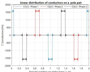
− − − = − − ∞ = − ) ) ( ( cos q 2 1 i p 1 k 2 L D A C 2k 1 2k 1 1 k 2k 1 iθ θ π (8)This distribution of conductors is a linear distribution along the stator bore. For the motor given on Table I, with a three phase winding, 12 conductors per slot, one conductor per pole and per phase with one layer, the linear distribution of conductors along the stator in function of the angular position is shown on Fig. 6.
Multiplying the conductor distribution function by the stator bore r and the angular slot opening χ, gives the number of conductors per slot (Fig. 7). On Fig. 7 positive number means ‘go’ conductors and negative number means ‘return’ conductors.
Fig. 6. Distribution conductor functions (m=1, nc=12 and nl=1).
Fig. 7. Number of conductors per slot, rχCk(θ), (m=1, nc=12 and nl=1)
Table I gives the magnitudes of the surface current density and the magnetic flux density waves, Km and Bm, of the motor
under study. Knowing the first harmonic of the conductor distribution functions from (8), it is possible to calculate the magnitude of the current Im from (6):
L D A 3 K 2 2 I 1 1 1 rms m= (9)
The real surface current density wave can be calculated from (6) and (8). Fig. 8 shows the distribution of surface current density wave on the stator bore at t = 0 and corresponding to the distributions of conductors of Fig. 6. It is compared to the fundamental of the surface current density wave. The distribution of the magnetic flux density wave shows that they are correctly tuned.
To get acquainted with conductor distribution functions, a winding with 12 conductors per slot, two conductors per pole and per phase and two layers has been also studied. The linear distributions of conductors along the stator in function of the angular position are shown on Fig. 9 and the surface current density on Fig. 10.
Each phase of the winding on Fig. 6 has the same number of turns than the winding on Fig. 9 (nt=48). This number of
output. Equation (9) can be used again to calculate the magnitude of the current Im. On Fig. 10 the surface current
density wave on the stator bore is shown. It can be seen that the surface current density wave is more close to a sinusoidal wave than on Fig. 8. Table IV gives the harmonic content of the surface current density wave at t = 0.
Fig. 8. Surface current density, its fundamental and magnetic flux density (m=1, nc=12 and nl=1).
Fig. 9. Distribution conductor functions ( m=2, nc=6 and nl=2).
Fig. 10. Surface current density, its fundamental and magnetic flux density (m=2, nc=6 and nl=2).
The results presented show that it can be very useful to design winding from conductor distribution functions. It is directly linked to the torque by (3) and (6).
TABLEIV
HARMONIC CONTENT OF THE SURFACE CURRENT DENSITY
Winding parameters THD (%) K1 (kA/m) K5/K1 (%) K7/K1 (%) K11/ K1 (%) K13/ K1 (%) m=1, nc=12, nl=1 84.16 274 90.7 82.6 59.2 46.7 m=2, nc=6 nl=2 85.23 273.7 6.54 6.33 89.75 86.69 V. NUMERICAL VALIDATION
To validate the joint validation of the rotor with Halbach array and the stator winding, a FEA is used. In order to show that the approach is robust, a winding with a worse THD is chosen (Table V). One pole of the designed motor is shown on Fig. 11. It is a motor with an Halbach array with 7 segments. The polarization of each a Halbach array segment is given on Table II.
Fig. 11. Studied motor with a multi-segmented Halbach array
Fig. 12. Surface current density, its fundamental and magnetic flux density (m=2, nc=6 and nl=1).
TABLEV
HARMONIC CONTENT OF THE SURFACE CURRENT DENSITY
THD (%) K1 (kA/m) K5/K1 (%) K7/K1 (%) K11/ K1 (%) K13/ K1 (%) 94.97 74.59 26.9 26.2 98 98.4
The motor has 2 slots per pole and per phase and one layer. Each slot has one conductor. The number of turns nt
angular slot opening χ is 7.66°. The surface current density wave is shown on Fig. 12. The harmonic content of the surface current density wave at t = 0 is given on Table V. Considering a sinewave flux density (1) and the conductor distribution function (8) the magnitude of the no-load flux of one phase is given by:
p L D A B l r rms vm 1 1 1 2 2 π = Φ (10)
where, Bm is the magnitude of the flux density wave given in
Table I. The back-emf per phase magnitude is:
Φ ω vm m
E = (11)
Fig. 13 compares the back-emf calculated by FEA and the one given by considering a sinusoidal back-emf.
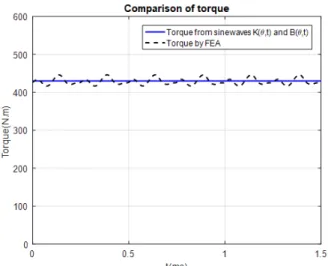
From (9) the magnitude of the currents has been calculated. In FEA, the phases of the motor have been supplied by sinusoidal currents and the torque on the rotor has been calculated. The torque is also calculated analytically with (4) by considering flux density (1) and sinusoidal surface current density (2) waves. The results of the two calculations are shown on Fig. 14.
Fig. 13. Back-emf calculated from (10)-(11) and by FEA.
Fig. 14. Torque calculated by (4) and by FEA
Fig. 13 and Fig. 14 show the electromechanical characteristics calculated by the proposed approach fit well the ones calculated by FEA. This approach allows to design quickly and with a good precision the performances of an electric motor considering fundamental waves (1) and (2).
VI. CONCLUSION
The analytical method presented here is devoted to high specific power SM-PMSM. From electric, magnetic and thermal loads and a rough definition of the sizes, we can calculate the torque, the back-emf of a sinusoidal motor. On one side, we define a Halbach array with seven segments per pole. An optimization procedure is employed to reach a sinusoidal magnetic flux density wave in the airgap. On other side, the design of the winding is done using conductor distribution functions. With a q phase sinusoidal current system, the sine wave surface current density obtained is tuned with the magnetic flux density wave in order to obtain the maximal tangential stress and then the maximum torque.
The optimization of the Halbach array is very elaborated but very efficient. The design of winding from conductor distribution functions is very simple. It is directly linked to the torque by equations (3) and (6). The errors from FEA are quite acceptable. It may be noted also that the conductor distribution functions of the winding chosen for the comparison are not really sinusoidal.
VII. APPENDIX
The conductor distribution and magnetomotive force (m.m.f.) functions, C(θ) and MMF(θ), can be expressed by the Fourier series decomposition:
(
θ)
(
θ)
θ C 2k 1p C 2k 1p C sn 1 n cncos( ) sin( ) ) ( =∞ − + − =(
θ)
(
θ)
θ mmf 2k 1 p mmf 2k 1p MMF sn 1 n cn ) ( sin ) ( cos ) ( =∞ − + − =where θ is the angular position. In the following, the parameters A2k-1, D2k-1and L2k-1are given in Table III.
A. Elementary full pitch winding
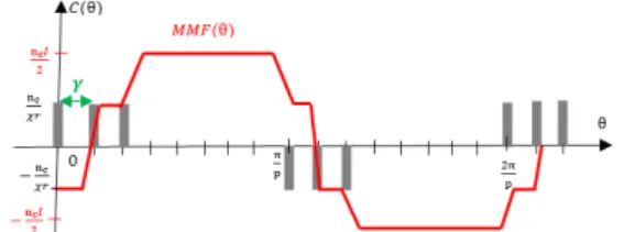
The conductor distribution and the m.m.f. waveforms of an elementary full pith winding are shown in Fig.15.
Fig. 15. Distribution conductor and magnetomotive force functions
The distribution conductor and the m.m.f. functions are given by:
(
)
(
)
(
)
χ(
θ)
χ π θ 2k 1 p 1 k 2 p 1 k 2 5 0 1 k r c n 4 C( ) sin . cos ( − ) − − ∞ = = (
θ)
χ χ π θ 2k 1 p 1 k 2 p 1 k 2 5 0 1 k p2k 1 I c n 4 MMF sin( ) ) ( ) ) ( . sin( ) ( ) ( − − − ∞ = − = (
θ)
θ 2k 1 p 1 k 2k 1 A C( ) cos ( − ) ∞ = − = (
θ)
θ 2k 1 p 1 k 2k 1 A p 1 k 2 rI MMF sin ( ) ) ( ) ( ∞ − = − − = B. Distributed winding with full pitch
The distribution conductor and m.m.f. waveforms of a full pitch distributed winding are shown in Fig.16
Fig. 16. Distribution conductor and Magnetomotive force functions of distributed winding
Using the C(θ) and MMF(θ) of the elementary coil, the distribution conductor and magnetomotive force functions can be deduced:
(
)
= − − − ∞ = − = m 1 j 1 j p 1 k 2 1 k 2k 1 A C(θ) cos( ) (θ ( )γ)(
)
= − − − ∞ = − − = m 1 j 1 j p 1 k 2 1 k 2k 1 A p 1 k 2 rI MMF sin( ) ( ( ) ) ) ( ) (θ θ γThe C(θ) and MMF(θ) of the distributed winding become:
(
θ)
θ 2k 1p 1 k 2k 1 D 1 k 2 A C( ) cos ( − ) ∞ = − − = (
θ)
θ 2k 1 p 1 k 2k 1 D 1 k 2 A p 1 k 2 rI MMF sin ( ) ) ( ) ( ∞ − = − − − = C. Distributed winding with several layers
The distribution conductor and m.m.f. force waveforms of distributed winding with layers are shown in Fig.17.
Fig. 17. Distribution conductor and magnetomotive force functions of distributed winding with several layers
By considering the layers of winding, C(θ) and MMF(θ) are expressed by: ( ) = = − − − ∞ = − − = l n l 1 l 1 l p 1 k 2 1 k 2k 1 D 1 k 2 A C(θ) cos ( ) (θ ( )ζ) ( ) = = − − − ∞ = − − − = l n l 1 l 1 l p 1 k 2 1 k 2k 1 D 1 k 2 A p 1 k 2 rI MMF sin ( ) ( ( ) ) ) ( ) (θ θ ζ
And can be simplified by:
(
θ)
θ 2k 1p 1 k 2k 1 L 1 k 2 D 1 k 2 A C( ) ∞ cos( − ) = − − − = (
θ)
θ 2k 1p 1 k 2k 1 L 1 k 2 D 1 k 2 A p 1 k 2 rI MMF sin( ) ) ( ) ( ∞ − = − − − − = VIII. REFERENCES[1] J. Pyrhönen, T. Jokinen, V. Hrabrovcova, "Design of rotating electrical machines," 2nd Edition, John Wiley & Sons, 2014.
[2] Y. Lefevre, S. El-Aabid, J. F. Llibre, C. Henaux, S. Touhami, "Performance assessment tool based on loadability concepts," The 18th
Symposium on Applied Electromagnetics and Mechanics, 3-6
September 2017, Chamonix, France.
[3] G. R. Slemon, "On the design of high-performance surface-mounted PM motors," IEEE Trans. Ind. App., vol.30, no.1, Jan/Feb 1994, pp.134-141.
[4] S. Touhami, Y. Bertin, Y. Lefèvre, J.F. Llibre, C. Henaux, M. Fénôt, "Lumped parameter thermal model of permanent magnet synchronous machines," International Conference on Modeling and Simulation of
Electric Machines, Converters, and Systems, Electrimacs, pp.1-6,
2017.
[5] M. Couderc, C. Henaux, B. Nogarède, "Electromagnetic analytical modeling of permanent magnets machine in view of their optimal design," International Conference on Electrical Machines (ICEM), 2008.
[6] D. Jarrot, Y. Lefèvre, C. Henaux, T. Meynard, "A tool to help to design windings of permanent magnet synchronous machines", 21st
International Conference on Electrical Machines (ICEM),
pp.1956-1962, 2014.
[7] F. Scuiller, E. Semail, J.-F. Charpentier, "General modeling of the windings for multi-phase ac machines," Eur. Phy. J. Appl. Phys. vol. 50, no. 3, 2010.
[8] Z. Q. Zhu and D. Howe, "Instantaneous Magnetic Field Distribution in Brushless Permanent Magnet dc Motors Part II: Armature-Reaction Field," IEEE Trans. on Magn., vol. 29, no. 1, January 1993.
[9] K. Atallah, Z. Q. Zhu, D. Howe, T. S. Birch, "Armature Reaction Field and Winding Inductances of Slotless Permanent-Magnet Brushless Machines," IEEE Trans. on Magn., vol. 34, no. 5, September 1998. [10] A. Tessarolo, L. Branz, C. Bruzzese, "Compact Analytical Expression
for the Load Torque in Surface Permanent-Magnet Machines with Slotless Stator Design," IEEE Workshop on Electrical Machines
Design Control and Diagnosis (WEMDCD), 2013.
[11] P. H. Mellor, R. Wrobel, "Optimization of a multipolar permanent-magnet rotor Comprising two arc segments per pole," IEEE Trans.
Ind. Appl., vol. 43, no. 4, pp.951-942, Jul/Aug. 2007.
[12] M. Markovic, Y. Perriard, "Optimization design of a segmented halbach permanent-magnet motor using an analytical model," IEEE
Trans. on Magn., vol. 45, no. 7, July. 2009.
[13] H. Huang, R. Qu, D. Li "Analysis and application of discrete Halbach magnet array with unequal arc lengths and unequally changed magnetization directions, "IEEE Trans. Applied. Supercond, vol. 28, no. 3, Apr. 2018.
IX. BIOGRAPHIES
Sarah Touhami was graduated from the "Ecole Nationale Supérieure d'Electrotechnique, d'Electronique, d'Hydraulique et d'Informatique de Toulouse" (ENSEEIHT – France) in Electrical Engineering in 2015. She is currently pursuing the Ph.D. degree in electrical engineering at the "Laboratoire Plasma et Conversion d’Energie" (LAPLACE), Toulouse.
Yvan Lefevre was graduated from the "Ecole Nationale Supérieure d'Electrotechnique, d'Electronique, d'Hydraulique et d'Informatique de Toulouse" (ENSEEIHT – France) in Electrical Engineering in 1983 and received his Doctorate degree from the "Institut National Polytechnique de Toulouse" in 1988. Since 1989, he is working as CNRS researcher in the LAPLACE "Laboratoire des Plasmas et de Conversion d’Energie".
Jean-François Llibre has received the Ph. D. degree in Electrical Engineering from National Polytechnic Institute of Toulouse in 1997. He is a lecturer since 1998 and teaches electrical engineering in the University Institute of Technology of Blagnac near Toulouse since 2003. He joined the GREM3 electrodynamics research group of LAPLACE laboratory in 2010.