HAL Id: hal-02053998
https://hal.archives-ouvertes.fr/hal-02053998
Submitted on 15 May 2019
HAL is a multi-disciplinary open access
archive for the deposit and dissemination of
sci-entific research documents, whether they are
pub-lished or not. The documents may come from
teaching and research institutions in France or
abroad, or from public or private research centers.
L’archive ouverte pluridisciplinaire HAL, est
destinée au dépôt et à la diffusion de documents
scientifiques de niveau recherche, publiés ou non,
émanant des établissements d’enseignement et de
recherche français ou étrangers, des laboratoires
publics ou privés.
Modelling and simulating the pump of an aerospace
electro-hydrostatic module for fault detection and
identification purposes
Jean-Charles Maré, Garance Vinson, Thomas Prado, Michel Combacau
To cite this version:
Jean-Charles Maré, Garance Vinson, Thomas Prado, Michel Combacau. Modelling and simulating
the pump of an aerospace electro-hydrostatic module for fault detection and identification purposes.
ASME Symposium on Fluid Power and Motion Control, Sep 2014, Bath, United Kingdom. pp.1-10,
�10.1115/FPMC2014-7803�. �hal-02053998�
MODELLING AND SIMULATING THE PUMP OF AN AEROSPACE
ELECTRO-HYDROSTATIC MODULE FOR FAULT DETECTION AND IDENTIFICATION
PURPOSES
Jean-Charles MARE
INSA, Université de Toulouse
Institut Clément Ader, F-31077 Toulouse, France
Garance VINSON Messier-Bugatti-Dowty, SAFRAN F-78141 Vélizy-Villacoublay, France Thomas PRADO Messier-Bugatti-Dowty, SAFRAN F-78141 Vélizy-Villacoublay, France Michel COMBACAU
CNRS LAAS, Univ de Toulouse, LAAS-UPS F-31400 Toulouse, France
ABSTRACT
This communication deals with the modelling and simulation of a fixed-displacement axial-piston pump used in aerospace electro-hydrostatic actuators. The pump model is developed in the LMS-AMESim simulation environment to support the development of fault detection and identification features. The model-based fault diagnosis method is introduced first and the modelling needs are addressed. Then, a system-level pump model is proposed with special considerations to model architecture. The different ways to improve the model's realism are reviewed, in particular concerning energy losses (bearing friction, leakages in gaps), barrel force balance, piston back pumping, piston eccentricity and pump loading for tests. Finally, directions of research in system-level modelling of hydraulic effects are suggested.
INTRODUCTION
Flight control and landing gear actuators are major secondary -i.e. not propulsive- power consumers in aircrafts. Servo-hydraulic actuators (SHA) supplied at a constant pressure from centralized hydraulic pumps are a well established standard since the sixties. However, they require hydraulic power networks that are heavy, difficult to integrate within the airframe and that offer poor power management capabilities. Towards greener, cheaper and safer aerospace, a high effort is placed today to develop power-by-wire (PbW) systems that only involve electrical power networks. For this reason, electro-hydrostatic actuators (EHA) offer an attractive design because they combine the advantages of both electrical and hydraulic technologies:
- easiness of control and efficiency of permanent magnet synchronous machines associated with high power inverters,
- efficiency, high power to mass ratio, easiness of passive mode and overload load protection of hydraulic cylinders equipped with piloted bypass and pressure relief valves.
Although EHAs have been introduced massively by Airbus on its A380, A400M and A350, they are still not sufficiently mature to be operated in front line. Therefore, they only serve as backup actuators. On their side, electro-mechanical actuators (EMA) also suffer from lack of maturity for safety critical applications, in particular regarding jamming, back-drivability, reflected inertia, nut-screw efficiency and overload protection. This is why EHAs can be considered as the most promising PbW actuators at medium term. To move EHA to service in front line for primary flight controls, costs have to be cut while reliability and availability have to be increased for long-life (typically 100 000 flight hours) applications. EHAs' costs can be significantly cut through modularization and standardization by developing electro-hydrostatic modules (EHM). These modules typically combine the electric motor and the hydraulic pump in a single unit [SAE ARP6154][Arnaud (2001)]. They play in EHAs the same role as servovalves do in SHAs. Health monitoring (HM) is considered as a convenient and efficient mean to meet the reliability and availability targets of front-line EHAs. However, most of the research and development efforts in HM are related to the electrical domain, focusing essentially on power electronics and electrical machines.
The present communication deals with the EHA pump fault detection and identification. The first section is dedicated to the health monitoring algorithms. A survey of candidate methods is proposed and justifies selecting the model-based approach. The Health-Monitoring module needs fault signatures, built from observable signals, to detect and identify the faults. The principle is to observe the system and to compare it with models outputs in order to determine which health state may have led to the observed behaviour. This method requires a complete model of the equipment, in nominal and faulty modes, represented into a formalism that suits the proposed diagnosis algorithms. The second section addresses in details the modelling and simulation of the EHA pump. The model is developed in order to serve as a virtual prototype. This prototype is used to investigate the richness of measured signals, to determine the best location and to specify the performance of sensors and finally to point out the fault signatures.
I. FAULTS DETECTION AND DIAGNOSIS OF HYDRAULIC PUMPS
1.1 Diagnosis methods
The objectives of fault detection and diagnosis are the diminution of the equipment interruption rate (improving the aircraft availability) and the minimization of the maintenance costs by improving fault localization and so decreasing aircraft down time. Implementing mature health monitoring features cannot be achieved without significantly improving the knowledge of the components wear and failures to enable proposing solutions for early fault detection and diagnosis.
There are three families of diagnosis methods: the experience based methods, the data driven methods, and the model based methods. For these three kinds of methods the principle is the same: the system is observed and its behaviour is compared with a data base in order to determine which health state may have led to the observed behaviour. Depending on the method, the data base is either statistical (i.e. a set of faults and consequences obtained from experience), or data recordings (obtained in service or during tests), or physical models outputs. The main reasons pumps fail are insufficient lubrication, fatigue, improper installation or contamination (fluid pollution for instance). In hydraulic pumps, cavitation leads to erosion, which leads to an increase of fluid leakage and a reduction in performance. Hydraulic pump wear reduces machine performance, causes secondary damage, and may be a precursor for catastrophic failure. Hydraulic pumps are not very much studied concerning Health Monitoring. Among literature only a few papers are found. They mostly use data driven methods.
The pressure ripples can be a good indicator of health degradation. For instance [Johnston (2010)] studies the wear of gear pumps used for delivery of high pressure fuel to aircraft
engine. Tests show more and more pressure ripples, measured with piezoresistive pressure transducers, at the high pressure outlet port with the wear of the pump. [Chinniah (2004)] develops a monitoring strategy for Electro-Hydrostatic Actuators. According to these studies gears wear in gear pumps can be deduced from the observation of pressure ripples, leakage flow, or with the use of a thermograph. [Hancock (2005)]use pressure signals for one piston pump fault detection. They compare power spectral analysis using FFT to wavelet packet analysis with neural networks.
Besides pump pressure, [Amin (2005)] uses case drain flow, and case drain temperature as the three indicators of pumps failures. Results are presented using pump degradation data from accelerated endurance tests provided by the Air Force Research Laboratory.
Another indicator of damage comes from vibration signals. In [Pawelski (2004)], a non-invasive diagnosis can determine the level of pump wear. Wear that changes the vibration characteristics of the pump can be observed with an accelerometer attached to the pump's case. A series of tests were performed. In [Mollazade (2009)], the vibration signal from a piezoelectric transducer was captured for normal and worn external gear hydraulic pumps used in the tractor steering system. The Power Spectral Density of vibration spectra is calculated to perform the diagnosis.
Sometimes data are available in service. For instance in [Gomes (2012)], data are field-data collected from two aircrafts that presented pump failures. When no degradation data are available in service, it is possible to perform dedicated accelerated life tests to obtain fault data, for instance in [Hancock (2005)], to accelerate pump wear and performance degradation by adding silica sand to the hydraulic reservoir to create contaminated hydraulic fluid. The pump performance is given by the output flow that decreases when the pump is damaged. Vibration signals were decomposed using wavelet packet analysis in order to establish the health state of the pumps.
Another possibility to obtain data is to model the faults. For instance in [Hancock (2005)], the faults on piston or swash plates are modelled as leakage flows. Moreover two pumps were tested, a healthy one and a one with a worn swash plate, to compare the results with the models. Wavelet analysis is then used to detect failures in hydraulic piston pump pressure discharge signals.
There are several problems with the implementation of sensors such as accelerometers. In aerospace applications, the pump environment is very noisy, with a lot of vibration generated by other equipment for instance. Moreover any sensor addition increases the weight and required space of the equipment, and decreases its reliability.
This makes it difficult to obtain relevant in-service degradation data since the number of sensors is limited. It is
also complicated to perform some degradation tests since they are destructive, costly and time consuming. Since the design of pumps is already based on models, a good idea is to model the pump nominal and faulty behaviour, in order to obtain a set of nominal and faulty data. This also allows the different possible sensors to be compared for choosing the more interesting one.
1.2 Model-based diagnosis method
The choice of the method between the three kinds of diagnosis methods depends on the nature of the degradation and fault data. In our case the experience based method is not chosen since the considered hydraulic pumps are too recent to have a sufficient amount of faults experience feedback.
Moreover there is no in-service pumps data available for now, and performing ageing tests, or tests with faulty pumps, to build a signals data base would be highly costly. That is why the data driven method is not chosen neither.
It is then the model based approach that is chosen. The advantages of this method are that it gives more specific results on the degradation mechanisms and on the physics of faults than the other methods, and it is more generic since once models are built for one kind of hydraulic pump, they can easily be tuned to be adapted to other kinds of pumps (with a greater number of pistons for instance).
More precisely, the model based diagnosis method requires building the model of the equipment in nominal behaviour, and also all the models of every fault that need to be monitored. Models can be analytical or numerical, depending on the knowledge on the fault mechanism considered. Faults to monitor are chosen assessing their frequency and consequences on the pump behaviour thanks to a Failure Mode Effect and Criticality Analysis (FMECA). They are characterized, and their models are incorporated into the nominal model. Some fault indicators are built. They are combination of observable parameters. The principle is that they take specific values for at least one fault. The best indicators are the one that change most during one fault, and do not change for every other fault. A fault signature is the set of indicators values when the fault occurs. Simulations enable all the faults signatures to be built.
In the best case, the model is supplied with the same inputs as the monitored equipment/system, including environment, to be able to compare the outputs of the model with the real equipment ones. In the present application, the environment is partially unknown. For instance, ambient temperature or the load applied on the flight control actuator (that depends on aircraft speed, turbulence and flight phase) are neither controlled nor monitored. The idea is then to perform the diagnosis under well-known and repeatable conditions, for instance during flight checks, post-flight checks, or pre-land tests. Thus, the simulations do not have to be run at every diagnosis time; the faults' consequences will always be the same in a given environment.
The use of the model-based method can also allow the different configurations of the actuator to be studied in order to define how to load the actuator and what the more suitable environment is. This enables choosing the most adapted configuration in order to obtain the best indicators. Another advantage with models is that all signals are observable with virtual sensors (no cost). Moreover, analysing the signal richness in case of faults allow sensors that give the best indicators to be selected for implementation.
1.3 Model for diagnosis
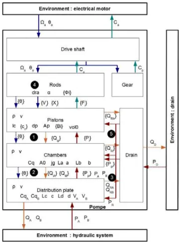
A model-based diagnosis method was proposed in [Vinson (2013)]. It requires a model of the equipment describing all the components, the exchanged parameters between components and with the environment, and the component private parameters, that are then used to model the damage of a component i.e. the faults on the hydraulic pump. Such a model is presented on Fig. 1. The model structure reflects the functional architecture of the pump with associated interactions and couplings: driveshaft, bevel gear, pushrods at mechanical level, piston chambers, distribution plate, pump housing at hydraulic level.
Figure 1. Architecture of the pump model used by the fault detection and identification algorithm
1.4 Critical faults
The FMECA performed on the hydraulic pump shows that the more critical faults are due to mechanical wear appearing at moving parts contacts level in the pump body, possibly made worst by hydraulic fluid pollution. The chosen faults are the increase of the clearance between the pistons and the barrel bores, and the wear of the part of the connecting plate facing the barrel.
II. VIRTUAL PROTOTYPE OF THE EHM PUMP
This section deals with the modelling and simulation of the MBD fixed-displacement, axial-piston, bent-axis EHA pump. This symmetrical 7-pistons pump, Fig. 2, is declined in different ranges depending on requirements. E.g., the Airbus A380 flies 12 pumps that serve in backup flight control actuators [Todeschi (07)] or in backup local hydraulic power generation for landing gears steering and braking [Dellac (04)].
Figure 2. EHA pump image (top) and schematic cut view (bottom) [Bucheton (2001)]
When used in EHAs, the pump is part of a closed hydraulic circuit making a hydrostatic transmission than can operate dynamically in the 4 power quadrants. It runs typically up to 350 bars, 15000 rpm, 40 l/mn with a service life greater than 50000 flight hours demonstrated at present.
2.1 Modelling need
In the field of actuation for aerospace, health monitoring is most of the time addressed considering failures at electrical motor, e.g. [Vinson (2012)] or at signal/power electronics, e.g. [Vohnout (2012)]. At a more mechanical or hydraulic level, Johnston [Johnston (2010)] pointed out the interest of using the pressure ripple at high pressure port as a good observable for aerospace fuel pumps. In that way, early degradation of bearings can potentially be detected before pump flow performance reduces. On basis of a simple model of the EHA, Chinniah [Chinniah (2014)] showed the interest of an extended Kalman filter to identify the fluid Bulk modulus, the gear pump viscous friction coefficient and the cylinder friction. However, only a global pump model was used (no piston level) to identify global parameters at EHA level, imposing a sine
position demand for a known load. A little attention was paid to the pump itself. Oppositely, Palazzolo [Palazzolo, (2008)] focussed his work on 3 types of leakages in a variable-displacement axial-piston pump: barrel chamber to drain, adjacent chamber to chamber through valve plate, delivery port to drain through valve plate. The flow models were quite simple: Poiseuille flow or equivalent turbulent leakage flow through fixed orifice. However, it was shown that using the output pressure signal was promising to discriminate the source of the leakage in a faulty pump. Fault signatures were generated combining time and frequency domains.
The common modelling and simulation of hydraulic pumps generally serve the main engineering needs. Distributed-parameters (3-D) models enable the local effects to be studied in order to support the detailed design of the pump, e.g. for hydrostatic or hydrodynamic bearing, force balancing or reduction of pressure ripple. On their side, lumped parameters (0-D) models are used to establish a global and a more system-level view of the pump, e.g. for simulating a whole EHA. Unfortunately, these latest models are generally obtained at the sacrifice of severe assumptions that remove the spatial effects to get algebraic or differential equations and that do not reflect the evolution and the influence of variable gaps within the pump.
2.2 Model architecture
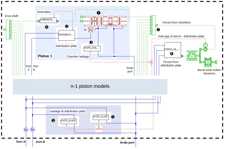
The present pump model is developed in the LMS-AMESim simulation environment to serve as a virtual prototype for supporting the design of a fault detection and identification module. In this attempt, an important activity consists in defining its architecture to ensure consistency with the model involved by the fault detection and identification module. The proposed model architecture is presented on Fig. 3. The model interfaces are the drive shaft and the three hydraulic ports: two power ports connected to the EHA cylinder and one drain port that collects the internal leakages of the pump to the EHA charge accumulator. Average ambient conditions are set by modifying the fluid temperature. The pump model is split into different submodels (numbers below refer to Fig.3):
piston/chamber model,
flow at slots through distribution plate,
chamber leakage to drain at barrel / distribution plate interface,
kinematics from drive shaft to piston,
leakage between power ports and drain at barrel / distribution plate interface,
hydrostatic and hydrodynamic forces on barrel at barrel / distribution plate interface,
Figure 3. Structure of the pump model, focused on hydraulics (rotational dynamics not displayed)
2.3 Model advances
According to the most critical faults to be detected, measuring pressure, estimating flow from cylinder rod velocity and estimating motor torque from windings current is considered as the most mature and efficient way to monitor the pump condition. For this reason, the pump model is developed with the main intention to increase the realism of the simulated driving torque and pressures or flow at hydraulic ports. This is mainly achieved by improving the simulation of energy losses (friction and leakage). In this attempt, the pump model has been developed with particular focus on friction at bearings level, piston/barrel wear and eccentricity, axial motion of barrel and pump characterisation process.
Friction in barrel ball bearings
The structure of friction model in bearings is well established with the new formulation proposed by SKF [SKF (06)]. In case of hydraulic machines, friction at bearing comes from two major contributors that are both load dependent:
- the speed dependent friction torque Mr associated with
hydrodynamic lubrication conditions during rolling (fluid kinetic viscosity times rotating speed N):
6 . 0 ) ( N k Mr r (1)
where coefficient kr introduces the influence of type and
size of bearing and load applied to the bearing.
- the speed independent friction torque Ms due to sliding
with friction coefficient :
s
s k
M (2)
where coefficient ks introduces again the influence of type
and size of bearing and load applied to the bearing. Finally, from the mechanical point of view, the model of bearings for system simulation can be structured extending the proposition given in [Maré (2012)]:
- a 2 times 1D model with 4 mechanical power ports (axial and radial motion, for inner and outer ring).
n-1 piston models
- one thermal port enabling the model to input the actual operating temperature and to output the heat flux generated by friction losses.
In that way, the bearing model is fully balanced, mechanically as well as thermally.
Calculating the bearing friction requires determining the axial and radial forces it has to hold. On one hand, the contribution of the bevel gear drive can be modelled quite easily using common gear mechanics. On the other hand, the contribution of the barrel through the axial preload spring is quite difficult (see dedicated paragraph). The significant influence of combined velocity and temperature for a given load is illustrated on Figure 4 which displays the shape of friction torque at rated operating pressure. It is interesting to note the change of rolling friction torque: the maximum value is quite unchanged but appears for an increasing speed versus temperature. Excepted at very low temperature, the sliding friction torque contributes in the same manner as the sliding friction torque at very low velocity. This situation is particularly important, e.g. for aileron actuators in cruise conditions: averagely, the flow demand is null while the pressure difference is high to hold a constant aileron steering in the presence of constant air load.
It must be remarked that the well established friction model in rolling bearing applies to permanently rotating application without speed reversal (e.g. engines or hydro power plants). There is lack of (published) information concerning the modelling of friction for bearings operating around null velocities with high acceleration: during a step response of an aerospace EHA, the pump runs from quasi null to 10000 rpm and returns to quasi null in 0.3 s.
Figure 4. Influence of speed and temperature on bearing friction (at rated output pressure)
Piston / barrel eccentricity and wear
At system level, modelling the friction force and leakage flow with a 0-D approach does not allow 3D dynamics of the piston to be considered. Indeed, piston's motion is excited by the driving force applied by the pushrod and by centrifuge effects. Solid models are two complex and fluid-structure interaction models cannot yet be extracted from distributed-parameters models. For this reason, friction and leakage are modelled using the conventional gap theory, with the assumption that piston and chamber axes keep parallel. The influence of shaft velocity can be introduced through the change of piston eccentricity in response to centrifugal force. Assuming a laminar flow in the annular gap enables the Hagen-Poiseuille theory to be used for linking the power variables according to the causal case used for simulation: flow rate Ql and viscous friction force Fv are a linear function
of the pressure difference P and the piston/barrel relative velocity v
P v rh h e h L r h e L rh rh F Q v l 0 2 0 0 2 0 3 0 0 ) / ( 1 2 / 5 . 1 1 6 (3)with r piston radius, h0 radial clearance, e eccentricity, L
piston length, fluid dynamic viscosity. As an illustration, Figure 5 points out the huge influence of eccentricity on axial friction force Fv.
Figure 5. Simulated peak friction force (103 bar, 10300 rpm, 40°C) 0 2 4 6 8 10 12 0 2 4 6 8 10 Eccentricity [m] Friction force 3,5 m 4,5 m 5,5 m 6,5 m 7,5 m 8,5 m
Bearing friction torques
0 2000 4000 6000 8000 10000 12000 Shaft speed (rpm) Mr , -55°C Mr , 0°C Mr , 40°C Ms , 40°C Ms , 0°C Ms , -55°C
In practice, at high angular velocities, pistons are submitted to significant centrifugal forces that tend to increase eccentricity which will increase leakage and friction. Unfortunately, although the annular gap model with eccentricity is available in the hydraulic component design
library of the simulation software, simulating this effect
requires further model development to express the radial hydraulic force that applies to the piston as a function of eccentricity, pressure and velocity.
Axial motion of barrel
In the patented pump design, the barrel is linked to the driver (reference 8 on Fig. 2) by a prism pair joint type and is axially spring loaded. This enables the barrel to float axially within the driver and determines the axial gap height between the barrel and the distribution plate. In order to simulate this degree of freedom, it is of particular importance to calculate the pressure forces that apply on the barrel. However, getting a 1-D model of the hydraulic force is not easy because the fluid velocity in the gap is at least 2-dimensional in laminar conditions (introducing the variation of the gap height would add a third dimension). This results from the combination of a radial flow in the gap from high pressure to low pressure domains and a tangent flow in the gap due to viscous entrainment under relative velocity between the barrel and the distribution plate.
The first one can be seen as the hydrostatic bearing force
Fh that is calculated by integration of the Navier-Stokes equation in polar coordinates within the considered domain [Bergada (2008)]. As a result, fluid viscosity and gap height do not appear in the integrated equation that only involves:
‐ 4 time variables (pressures P1 and P2 at power ports and P0
at drain, barrel angular position relative to plate), ‐ number of pistons k,
‐ area A of holes in the barrel for connection to chambers, ‐ geometry of the kidney slots (angle width , inner and
outer radii R2 and R3),
‐ geometry of the barrel (inner and outer radii R1 and R4)
) , , , , , , , , (P0,P1 P2 A R1 R2 R3 R4 f Fhs
The second one can be seen as the hydrodynamic force
Fhs that come from the tangential shear rate in the gap, which
in its turn introduces the influence of height and fluid viscosity. This force is often neglected in axial piston pumps because they never run in the vicinity of null velocity in conventional applications. As mentioned above, this is not the case in EHAs that are used for position control. For this reason, it should be important to get a model of hydraulic forces that covers the whole domain of operation. However, getting an algebraic model from formal integration of the Navier-Stokes equations is not feasible, as mentioned in [Bergada (2008)]. Although the pump model currently
considers the hydrostatic axial force only, it has still to be improved in order to include the hydrodynamic effect.
On its side, the frictional moment transmitted by the driver to the barrel is commonly estimated assuming a linear velocity distribution under pure tangential shear [Ivantysyn (2001)].
2
1 2 2 2 3 2 4 2h R R R R Mb (4) Once again, this model has to be improved to be applicable at very low velocity (from 10 to 100 rpm) when the flow in gap becomes more radial than tangential. The same remark applies to the modelling and simulation of the leakage flow in the gap.III. APPLICATION: FAULT DIAGNOSIS FOR AN AXIAL PISTON PUMP OF AN ELECTRO-HYDROSTATIC ACTUATOR
3.1 Sensors and observable signals
On the electrical actuator used for flight control, steering, and extension/retraction of landing gears, there are a few sensors. Monitored signals are:
‐ the differential pressure, ‐ the accumulator pressure,
‐ the hydraulic jack position (only for flight control and steering),
‐ the fluid temperature,
‐ the motor windings temperature,
‐ the motor position, from which can be deduced the motor rotation speed,
Although there is no flow-meter, the pump output flow rate can be identified from the motor speed and the jack position measured signals.
These signals are available without any sensor addition, so they are natural candidates to use in priority for the design of fault indicators.
It is interesting to emphasize the following effect that has already been mentioned in [Maré (2006)]. In real operation, the pump housing is connected to a charge accumulator which aims at compensating the change of fluid volume versus pressure and temperature, the external leakages and the deformation of walls under pressure. The accumulator is connected to each hydraulic power line by a re-feeding check valve. When the pump output pressure reduces, the fluid expands and the walls retract. The corresponding fluid flow cannot pass through the re-feeding valves that are closed. Therefore, the fluid flows from power lines to the accumulator through the pump internal gaps and housing. Pressures in the power lines become equal and decay to the charge pressure
with a first order dynamics. This dynamics comes from the combination of a resistance effect (overall hydraulic resistance of pump gaps) and a capacitance effect (fluid and walls compliance). In the test simulated on Fig. 6, the pump is driven at a variable speed between -8000 and 8000 rpm and is loaded by a fixed hydraulic resistance (1.5 mm2) connecting the two power ports A and B. Charge pressure is 50 bar. It is clearly observed that when the pump is unloaded (as a consequence of speed reduction at t = 1.2 s), the pressures at power ports become equal and decay at a rate that depends on the pump leakage. This rate appears as an interesting candidate to get a good signature of the pump leakage even if there is a very little change in the pressures themselves.
Figure 6. Pump speed and pressures with gap at distribution plate 12 m (upper) and 17 m (lower)
3.2 Faults signatures
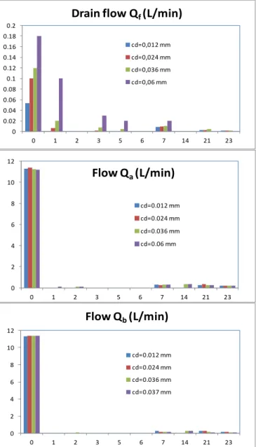
Simulations were run with the virtual prototype, in order to identify candidates fault indicators. In the following example, the clearance between one piston and the barrel is progressively increased from 12 to 60 m to simulate the wear of one piston. The differential pressure is set to 103 bars, the gap between the barrel and the distribution plate is 16 µm. Mechanical speed is 10366 rpm. The output flow QA at
hydraulic port A, the input flow QB at hydraulic port B and the
leakage flow QF at drain port D are observed. Figure 7
displays the magnitude spectrum as a function of clearance.
0 0.02 0.04 0.06 0.08 0.1 0.12 0.14 0.16 0.18 0.2 0 1 2 3 5 6 7 14 21 23
Drain flow Q
f(L/min)
cd=0,012 mm cd=0,024 mm cd=0,036 mm cd=0,06 mm 0 2 4 6 8 10 12 0 1 2 3 5 6 7 14 21 23Flow Q
a(L/min)
cd=0.012 mm cd=0.024 mm cd=0.036 mm cd=0.06 mm 0 2 4 6 8 10 12 0 1 2 3 5 6 7 14 21 23Flow Q
b(L/min)
cd=0.012 mm cd=0.024 mm cd=0.036 mm cd=0.037 mmFigure 7. Magnitude spectrum of hydraulic flows vs. angular frequency for different piston/barrel clearance cd (simulation results)
The conclusion is that new harmonics appear in case of one piston unexpected wear. Since the pump has 7 pistons, it is not surprising that the new harmonics numbers are multiple of 7. The frequency analysis of the hydraulic flow can then be an indicator of wear.
CONCLUSION
The different ways of improving the model's realism of an EHA pump has been reviewed with respect to the needs induced by the development of fault detection and identification features. A structured architecture of the pump model has been firstly proposed for fault diagnosis and for virtual prototyping. Then, the virtual prototype has been improved using a step-by-step process. When developing the models, it has clearly appeared that there is a need for advanced parameters of 0-D models, in particular for friction in bearings operating around null velocity at high angular acceleration and for flow and hydraulic forces invariable gaps. Referring to basic geometries where models can be expressed formal induce severe assumptions that generate unacceptable inaccuracy. Flow and forces models have to be established from distributed models in order to better reproduce the effect of pressure, velocity and gap height, e.g. using scaling-law based meta-models as proposed in [Budinger (2014)]. Model improvement requires also the thermal effects to be considered. Although thermal-hydraulic models are available in today's software libraries, the same need appears to support model parameterization.
REFERENCES
Amin S., Byington C., Watson M., 2005, "Fuzzy Inference and Fusion for Health State Diagnosis of Hydraulic Pumps and Motors." Fuzzy Information Processing Society, 2005.
NAFIPS 2005. Annual Meeting of the North American ,
pp.13,18, 26-28 June
Arnaud A., 1998, "An approach to EHA standardization",
Proceedings of the International Conference on Recent Advances in Aerospace Hydraulics, Novembre 24-26, Insa
Toulouse, France, pp 105-116
Bergada M., Watton J, Kumar S., 2008, "Pressure, flow, force, and torque between the barrel and port plate in an axial piston pump", Journal of Dynamic Systems, Measurement and
Control, vol. 130, no. 1, 16 pages
Bucheton D., 2001, "Pompe à pistons axiaux du type à axe brisé", European patent EP 1 167 756 A1, 2 January
Budinger M., Hazyuk I., Maré J-C., 2014, "Scaling-law-based Metamodels for the Sizing of Actuation Systems",
Proceedings of the International Conference on Recent Advances in Aerospace Actuation Systems and Components,
Insa Toulouse, France, April 2-3, pp 129-135
Chinniah Y. A., 2014, "Fault Detection in the Electrohydraulic Actuator using Extended Kalman Filter", PD thesis, University of Saskatchewan
Dellac S., Ternisien D., 2014, "Airbus 380 Electro-Hydraulic Back-Up Architecture for Braking and Steering Systems",
Proceedings of the International Conference on Recent Advances in Aerospace Actuation Systems and Components,
Insa Toulouse, France, Novembre 24-26, pp 103-108
Gao Y., Zhang Q., Kong X., 2003, "Wavelet-based pressure analysis for hydraulic pump diagnosis", ASAE transaction, vol. 46, pp 969-976
Gomes J. P. P., Leão B. P., Vianna W. O. L., Galvão R. K. H., Yoneyama T., 2012, "Failure Prognostics of a Hydraulic Pump Using Kalman Filter", Annual Conference of the Prognostics
and Health Management Society
Hancock K. M., Zhang Q., 2005, "A Hybrid Approach to Hydraulic Vane Pump Health Monitoring and Fault Detection", ASAE Annual Meeting transaction, vol. 49(4), pp 1203−1211
Hancock, K. M., Zhang Q., 2005, "Maintenance and fault diagnostic tools for hydraulic pumps", 50th National
Conference on Fluid Power proceedings, Milwaukee,
Wisconsin, pp 363-369
Ivantysyn J., M. Ivantysynova, 2001, “Hydrostatic pumps and motors”, Academia Books international, New Delhi, India Johnston N., Todd C. 2010, "Condition Monitoring of Aircrafts Fuel Pumps using Pressure Ripples Measurements",
Fluid Power and Motion Control, September 15-17, Bath,
England, pp 161-174
Maré J-C., 2012, "2-D lumped-parameters modelling of EMAs for advanced virtual prototyping", Proceedings of the
International Conference on Recent Advances in Aerospace Actuation Systems and Components, Toulouse, France, June
13-14, pp 122-128
Mollazade K., Ahmadi H., Omid M., Alimardani R., 2009, "Vibration-Based Fault Diagnosis of Hydraulic Pump of Tractor Steering System by Using Energy Technique", CCSE
Modern Applied Science, vol 3, no 6, June
Palazzolo J-J., Scheunemann L.D., Hartin J.R., 2008, "Leakage Fault Detection Method for Axial-Piston Variable Displacement Pumps", Aerospace Conference, IEEE, 1-8 March
Pawelski P., He D., 2004, "Vibration based pump health monitoring", SAE transactions, vol. 113, no 2, pp 636-639 SAE ARP 6154, "EHM general specifications", Aerospace
Recommended Practice under completion by A-6B2 EHA IAP
Committee of Society of Automotive Engineers, http://standards.sae.org/wip/arp6154/
SKF, 2006, "Friction chapter", SKF general catalogue
Todeschi M., 2007, "A380 flight control actuation - Lessons learned on EHAs design", Proceedings of the International
Conference on Recent Advances in Aerospace Actuation Systems and Components, Insa Toulouse, France, June 13-15,
pp 21-26
Vinson G., Combacau M., Prado T., Ribot P., 2012, "Permanent magnets synchronous machines faults detection and identification", 38th Annual Conference on IEEE
Industrial Electronics Society (IECON), Montréal, Canada,
October 25-27
Vinson G., Ribot P., Prado T., Combacau M., 2013, "A Generic Diagnosis and Prognosis Framework: Application to Permanent Magnets Synchronous Machines". Proceedings of
the Prognosis and Health Management Conference (PHM)
Vohnout S., Bodden D., Uk Kim B., Wagoner R., Kunst N., Edwards P., Gleeson B., Cascio D., Brzuszkiewicz S., Wagemans R., Round M., Clements N. S., 2012, "Prognostic Enabling of an Electrohydrostatic Actuator (EHA) System",
Proceedings of the Annual Conference of Prognostics and Health Management Society, Mineapolis, USA, 13 September,
![Figure 2. EHA pump image (top) and schematic cut view (bottom) [Bucheton (2001)]](https://thumb-eu.123doks.com/thumbv2/123doknet/12497884.340020/5.918.67.440.449.628/figure-eha-pump-image-schematic-cut-view-bucheton.webp)
![Figure 5. Simulated peak friction force (103 bar, 10300 rpm, 40°C) 02468101202468 10Eccentricity [m]Friction force 3,5 m4,5 m5,5 m6,5 m7,5 m8,5 mBearing friction torques](https://thumb-eu.123doks.com/thumbv2/123doknet/12497884.340020/7.918.547.792.640.958/figure-simulated-friction-eccentricity-friction-mbearing-friction-torques.webp)