Pépite | Nanocomposites à base d’oxyde de graphène réduit : synthèse, caractérisation et application
199
0
0
Texte intégral
(2) Thèse de Amer Khudair Hussien Al-Nafiey, Lille 1, 2016. ABSTRACT Since the first appearance in 2004, graphene and its derivatives have attracted considerable attention in different fields and created a revolution in materials science and condensed matter physics, owing to their amazing unique physical and chemical properties. These desirable properties have inspired the development of low-cost and high-yield preparation methods of chemically-derived graphene (reduced graphene oxide). The chemical reduction of graphene oxide (GO) is the most promising and effective method for the synthesis of reduced graphene oxide (rGO) because of its relatively large scale and low cost. Additionally, many investigations focused on the applications of graphene-based composites as catalysts for pollutants removal. Also, modified graphene can adsorb heavy metal ions with high efficiency and selectivity, and thus reduces them to metals for recycling. The objective of my thesis is to develop simple, environmentally friendly, low cost, and controllable approaches for the chemical reduction of GO to rGO and its decoration with metal and metal oxide nanoparticles. These techniques use arginine and sodium borohydride as reducing agents, and silver nitrate, nickel chloride or cobalt chloride as a source for the metal/metal oxide nanoparticles. The following nanocomposites: rGO/Arg-Ag NPs, rGO-Ni NPs and rGO-Co3O4NPs were successfully synthesized. The resulting rGO-based nanocomposites were characterized by a variety of different techniques, including , SEM, TEM, XPS, FTIR, Raman, XRD, UVVis and TGA. The analysis revealed that these graphene-based nanocomposites have excellent properties and stability. We successfully applied the rGO-based nanocomposites as a catalyst for the reduction of 4nitrophenol to 4-aminophenol, with a full reduction time in less than 1, 5 and 1 min at room temperature and remained active more than 4, 10, and 10 cycles for rGO/Arg-Ag NPs, rGO-Ni NPs and rGO-Co3O4NPs, respectively. The Co3O4/rGO displayed high adsorption capacity for three organic dyes. The Co3O4/rGO nanocomposite removed 96%, 91% and 92% of RhB, MO and Rose Bengal after 2, 1 and 2 min, respectively. The maximum adsorption capacity of Cr (VI) was 222.2 mg. g-1, which is very close to the experimental value of 208.8 mg.g-1. These results were fast and highlyefficient compared with other reported data. Key words: graphene oxide (GO), reduced graphene oxide (rGO), reduction, catalyst, adsorption, dyes, chromium, environmental applications. 2 © 2016 Tous droits réservés.. doc.univ-lille1.fr.
(3) Thèse de Amer Khudair Hussien Al-Nafiey, Lille 1, 2016. RESUME Nanocomposites à base d’oxyde de graphène réduit : Synthèse, caractérisation et application Depuis la première apparition en 2004, le graphène et ses dérivés ont attiré une attention considérable dans différents domaines et créé une révolution dans la science des matériaux et la physique de la matière condensée, en raison de leurs propriétés physiques et chimiques uniques. Ces propriétés souhaitables ont inspiré le développement de faible coût et à haut rendement à partir de la méthode chimique de synthèse d’oxide de graphene et de la (Oxide de graphène réduit). La réduction chimique de l'oxyde de graphène (GO) est la méthode la plus prometteuse et efficace pour la synthèse d'oxyde de graphène réduit (RGO) en raison de leur faible coût de synthèse et leur grande quantité de production. En outre, de nombreuses recherches ont était faite sur des applications des composites à base de graphène en tant que catalyseurs pour la dégradation des polluants. En outre, le graphène modifié peut absorbe des ions de métaux lourds avec une grande efficacité et une sélectivité, et réduit ainsi les métaux à des fins de les recyclé. L'objectif de ma thèse est de développer une méthode simple, pas chère, et les approches contrôlables pour la réduction chimique de GO a du rGO et le décoré avec des nanoparticules. Ces techniques utilisent le borohydrure de sodium et d'arginine comme agent réducteur, et le nitrate d'argent, le chlorure de nickel ou le chlorure de cobalt en tant que source pour les nanoparticules de métal / métal oxideé. Les nanocomposites suivantes: rGO / Arg-Ag NP, rGO-Ni NPS et rGO-Co3O4NPs ont été synthétisés avec succès. Les nanocomposites à base de RGO résultants ont été caractérisés par une variété de techniques différentes, y compris, MEB, TEM, XPS, FTIR, Raman, XRD, UVVis et TGA. L'analyse a révélé que ces nanocomposites à base de graphène ont d'excellentes propriétés et la stabilité. Nous avons appliqué avec succès les nanocomposites à base de rGO en tant que catalyseur pour la réduction du 4-nitrophénol de 4-aminophénol, avec un temps de réduction complète en moins de 1, 5 et 1 min à une température ambiante et il a resté actif plus de 4, 10, et 10 cycles de rGO / Arg-Ag NP, rGO-Ni NPS et rGO-Co3O4NPs, respectivement. Le Co3O4 / rGO affiche une capacité d'adsorption élevée pour trois colorants organiques. Le nanocomposite Co3O4 / rGO retiré 96%, 91% et 92% des RhB, MO et Rose Bengale après 2, 1 et 2 min, respectivement. La capacité d'adsorption maximum de Cr (VI) était de 222,2 mg. g-1, qui est très proche de la valeur expérimentale de 208,8 mg.g-1. Ces résultats ont été rapides et très efficace par rapport à la bibliographe. Mots clés: l'oxyde de graphène (GO), graphene oxide réduit (rGO), la réduction, le catalyseur, l'adsorption, de colorants, de chrome, les applications environnementales. 3 © 2016 Tous droits réservés.. doc.univ-lille1.fr.
(4) Thèse de Amer Khudair Hussien Al-Nafiey, Lille 1, 2016. ACKNOWLEDGEMENTS This research work was carried out in the Nanobiointerfaces group at Institut d'Electronique, de Microélectronique et de Nanotechnologie (IEMN). I would like to express my deepest gratitude to all those people who have helped and encouraged me in the successful completion of my doctoral study. Primarily, I would like to give my most sincere thanks to my supervisors, Dr. Rabah Boukherroub and Dr. Brigitte Sieber, for their guidance, kindness, stimulating discussion, continued advice permanent support over past few years, as well as the time and patience they spent in reading and correcting the manuscript of this dissertation. With their enormous help and supervisions, I have obtained a lot of precious research experience such as scientific thinking, knowledge in chemistry and materials, as well as laboratory techniques. It was truly a great pleasure and privilege to study under their mentorships. It is my honor to have the chance to learn from them. My special thanks go to Prof. Sabine Szunerits from our group for her generous cooperation, helpful discussions and valuable suggestions. I would like to express my thanks to Prof. Zineb Mekhalif and Prof. Falah H. Hussein for accepting to be the reviewers of the manuscript of my thesis and the committee members of my defense. I’m so grateful for their time and precious opinions. I would like to sincerely thank Dr. Ayad Alkaim and Prof. Tuami Lasri for accepting to be the committee members of my defense. I truly appreciate your time and your helpful comments. My heartfelt thanks go to all my colleagues for all the help, discussions, and sharing. To Dr. Yannick Coffinier, Dr. Alexandre BARRAS, Dr. Ahmed Addad it’s such a pleasure to work with you in the laboratory in past few years and for all the kind help and valuable advices. Also every member of my research group Lionel, Palan, Nadia, Manu, Stefka, Nazek, Roxana, Florina, Pawan, Faouzia, Hosam … It is truly my honor to work with all of you. I would like also to thank my friends, Ahmed Al Mousawi, Alaa Al-Seraih, Ameen Al-ali, Ali Al-furaiji , Dhia Ghibi ,Abass Al-Amiry, Mdlj Mayssam, Hussein Taher, Haider Al-Kinany….for their friendship and big supports. In particular, I wish to thank the Iraqi Management Scholarships and Cultural Relations at the Ministry of Higher Education and Scientific Research in Iraq and the France government represented by CAMPUS FRANCE, which offered me the opportunity to pursue my PhD study in France.. 4 © 2016 Tous droits réservés.. doc.univ-lille1.fr.
(5) Thèse de Amer Khudair Hussien Al-Nafiey, Lille 1, 2016. Finally, to memory of my father, who is alive with me and to my mother, who always pray for me, and overwhelm me with love. To my wife and my lovely kids, who supported me and give me the happiness at any time and my family for their support and motivation over the years. Their encouragements and warm words of advice have been very instrumental in my life.. Amer Khudair Hussien Al-Nafiey Lille October 2015. 5 © 2016 Tous droits réservés.. doc.univ-lille1.fr.
(6) Thèse de Amer Khudair Hussien Al-Nafiey, Lille 1, 2016. Table of Contents CHAPTER 1 ………………………………………………………………………..11. 1.. INTRODUCTION.................................................................................................................. 11 1.1.. Introduction of graphene ........................................................................................ 12. 1.2.. Synthesis of graphene ............................................................................................. 13. 1.2.1.. Chemical vapor deposition (CVD) ................................................................. 15. 1.2.2.. Epitaxial growth ............................................................................................... 18. 1.2.3.. Mechanical exfoliation ..................................................................................... 19. 1.2.4.. Chemical reduction of graphene oxide (GO)................................................. 20. 1.2.5.. Thermal reduction of GO ................................................................................ 29. 1.2.6.. Photo-catalytic method .................................................................................... 30. 1.2.7.. Electrochemical method .................................................................................. 30. 1.2.8.. Other methods .................................................................................................. 31. 1.3.. Properties of graphene ............................................................................................ 33. 1.3.1.. Surface properties ............................................................................................ 33. .1.3.2. Electronic properties ..................................................................................... 34. 1.3.3.. Optical properties ............................................................................................ 35. 1.3.4.. Mechanical properties ..................................................................................... 36. 1.3.5.. Thermal properties .......................................................................................... 37. 1.3.6.. Photo-catalytic properties ............................................................................... 38. 1.3.7.. Magnetic properties ......................................................................................... 39. 1.4.. Characterizations of graphene ............................................................................... 40. 1.4.1.. Morphology (SEM, TEM and AFM) ............................................................. 40. 1.4.2.. Raman spectroscopy ........................................................................................ 42. 1.4.3.. X-ray photoelectron spectroscopy (XPS) ....................................................... 43. 1.4.4.. UV-Visible spectroscopy .................................................................................. 44. 1.4.5.. X-ray diffraction (XRD) .................................................................................. 45 6. © 2016 Tous droits réservés.. doc.univ-lille1.fr.
(7) Thèse de Amer Khudair Hussien Al-Nafiey, Lille 1, 2016. 1.4.6.. Thermogravimetric analysis (TGA) ............................................................... 46. 1.4.7.. FTIR spectroscopy ........................................................................................... 47. 1.5.. Decoration of graphene with metal nanoparticles ............................................... 48. 1.5.1.. In situ decoration of nanoparticles onto graphene, GO and rGO ............... 50. 1.5.2.. Ex-situ decoration of nanoparticles on graphene, GO and rGO ................. 53. 1.6.. References ................................................................................................................ 56. CHAPTER 2 ........................................................................................................................... 76 Reduced graphene oxide decorated with silver nanoparticles ........................................... 76 2.1. Introduction ............................................................................................................. 76. 2.2. Graphene decorated with silver nanoparticles ..................................................... 77. 2.3. Reduction of graphene oxide by L-Arginine......................................................... 80. 2.4. Reduced graphene oxide decorated with silver nanoparticles (rGO-AgNPs) ... 85. 2.5. Reduction of 4-nitrophenol to 4-aminophenol using graphene-based nanometals 92. 2.5.1. Introduction ......................................................................................................... 92. 2.5.2. Catalytic reduction of 4-nitrophenol by rGO/Ag NPs composite ................... 99. 2.6. Conclusion .............................................................................................................. 104. 2.7. References .............................................................................................................. 106. CHAPTER 3 ......................................................................................................................... 113 Reduced graphene oxide decorated with nickel nanoparticles ........................................ 113 3.1.. Introduction ....................................................................................................... 113. 3.2.. Reduced graphene oxide decorated with nickel/nickel oxide nanoparticles 114. 3.3.. Reduced graphene oxide decorated with Ni NPs (rGO/Ni NPs) ....................... 122. 3.4. 3.4.1.. Catalytic reduction of 4-nitrophenol................................................................ 132 Reduction of 4-nitrophenol to 4-aminophenol by rGO-Ni NPs ................. 132. 3.5.. Conclusion .......................................................................................................... 134. 3.6.. References........................................................................................................... 136. 7 © 2016 Tous droits réservés.. doc.univ-lille1.fr.
(8) Thèse de Amer Khudair Hussien Al-Nafiey, Lille 1, 2016. CHAPTER 4 ......................................................................................................................... 143 Preparation, characterizations and applications of reduced graphene oxide decorated with Co3O4 nanoparticles (rGO-Co3O4) nanocomposite ............................................... 143 4.1. Introduction .................................................................................................................. 143 4.2. Decoration of cobalt oxide on graphene sheets as a model to metal oxide/graphene nanocomposites .................................................................................................................... 144 4.3. Reduced graphene oxide decorated with cobalt oxide nanoparticles (rGO-Co3O4 NPs). ...................................................................................................................................... 146 4.4. Characterizations of rGO/Co3O4 nanocomposite .................................................... 147 4.5. Applications .................................................................................................................. 158 4.5.1.. Catalytic reduction 4-nitrophenol ................................................................ 158. 4.5.2.. Treatment of wastewater using graphene/nanomaterials .......................... 161. 4.5.3.. Chromium Cr(VI) removal from aqueous solution by rGO-Co3O4. nanocomposite .............................................................................................................. 171 4.5.4.. Dye removal from aqueous solution ............................................................ 177. 4.6. References ..................................................................................................................... 184 Chapter 5 .............................................................................................................................. 191 CONCLUSION AND PERSPECTIVES ........................................................................... 191 Appendix ............................................................................................................................... 194 EXPERIMENTAL PART ................................................................................................... 194 1.. Chemicals ........................................................................................................... 194. 2.. Preparation of graphene oxide (GO) ............................................................... 194. 3.. Instrumentation ................................................................................................. 195. 3.1.. X-ray photoelectron spectroscopy (XPS) ........................................................ 195. 3.2.. Fourier-transform infrared (FTIR) spectroscopy .......................................... 196. 3.3.. Raman spectroscopy .......................................................................................... 196. 3.4.. UV-Vis measurements ....................................................................................... 197. 8 © 2016 Tous droits réservés.. doc.univ-lille1.fr.
(9) Thèse de Amer Khudair Hussien Al-Nafiey, Lille 1, 2016. General Introduction and Objective Graphene a monolayer of carbon atoms densely packed in a honeycomb lattice was isolated for the first time in 2004. In recent years, the research on graphene and its derivative has been popular and extensive and generated tremendous interest in a wide range of research activities coming from its best properties like highest conductivity, high surface area and hardest materials. A facile and versatile pathway to obtain Graphene based nanocomposites is through the reduction of Graphene Oxide (GO). Several methods for reduced graphene oxide (rGO) that were developed include chemical, thermal, electrical, and optical process. Additionally , reduced. graphene oxide (rGO)-based nanocomposites has been synthesized for potential applications in electronics, energy storage, catalysis, and gas sorption, storage, separation and sensing and so on. On the other hand, metal nanoparticles, have been exhibited remarkable in many applications but during synthesis, these nanoparticles tend to agglomerate resulting in loss of their nanoscale properties. Since reduce graphene oxide have high surface area can serve as nucleation sites for, it can be used as a substrate to deposit metal nanoparticles. This will reduce agglomeration of nanoparticles, and supported the metal nanoparticles properties as well as the graphene properties. Moreover, water pollution is world- wide environmental concern coming from heavy metal ions and organic dyes in wastewater that strongly threatens human, animals and plants. So, many effective strategies of water purification can be categorized into pollutants adsorption and conversion one of them, rGO-based nanocomposites typically show promising nanocomposites effective on reduced these pollutant species. So, we will develop a simple, low cost, high quantity and controllable approaches for the chemical reduction of graphene oxide to rGO and decorate with nanometals and nanometals oxide. These techniques are based on use of arginine, nickel chloride, and sodium borohydride with cobalt chloride as reducing agents as well as a sources for the nanometals. We have successfully obtained these nanocomposites (rGO/Arg-Ag NPs, rGO-Ni NPs and rGO-Co3O4 NPs). This thesis content four chapters describe all the novel method that successfully reduced graphene oxide and decorated with nanometals and nanometals oxide. Chapter 1, will be a general overview on graphene and graphene-based nanocomposite, preparation, characterization, and properties and their potential applications. In (Chapter 2), we will describe the bibliographer about rGO/Ag NPs preparation and developed environmentally friendly approaches method of preparation rGO/Arg-Ag NPs from GO, arginine and silver nitrate by novel chemical reduction and show there characterizations by. 9 © 2016 Tous droits réservés.. doc.univ-lille1.fr.
(10) Thèse de Amer Khudair Hussien Al-Nafiey, Lille 1, 2016. using different techniques. rGO/Arg-Ag NPs was used as a catalyst to reduction 4-nitrophenol to 4-aminophenol. Chapter 3, we will show, it can be reduced graphene oxide and decorated with nickel nanoparticles by simple, novel chemical reduction method using only GO and nickel chloride. The characterizations doing by different techniques and show us that this method was able to reduce graphene oxide and decorated with nickel nanoparticles (rGO-Ni NPs). This nanocomposite also applied as catalyst to reduction 4-nitrophenol to 4-aminophenol. In Chapter 4, we developed novel, quick, room temperature and simple method to reduce graphene oxide and decorated with cobalt oxide by using sodium borohydride with cobalt chloride as reducing agents as well as a sources for the nanometals (rGO-Co3O4 NPs). This rGO-Co3O4 NPs was characterized by different techniques and the result shown that the cobalt oxide anchored on the reduce graphene oxide successfully. We used this rGO-Co3O4 NPs as a catalyst to reduction 4-nitrophenol to 4-aminophenol and adsorbed dyes and Cr (VI) from wastewater.. 10 © 2016 Tous droits réservés.. doc.univ-lille1.fr.
(11) Thèse de Amer Khudair Hussien Al-Nafiey, Lille 1, 2016. CHAPTER 1 1. INTRODUCTION Graphene has become an interesting nanomaterial from the time of its discovery due to its fascinating physical and chemical properties and for its promising applications [1, 2]. Graphene in simple terms is a thin layer of pure carbon; it is a single, tightly packed layer of carbon atoms that are bonded together in a hexagonal honeycomb lattice. In complex terms, it is an allotrope of carbon in the structure of a plane of sp2-bonded atoms (Figure 1.1) [3]. Before that, graphene had been investigated theoretically for over sixty years, although its existence as 2D crystals in free space was thought impossible [2]. In the last years, graphene has been the most studied material, attracting the attention of the entire scientific community for its exceptional physical and chemical properties [4]. Since the Geim and Novoselov’s Nobel Prize in Physics for isolation of graphene by mechanical exfoliation of graphite in 2004 [5, 6], many researchers in the world searched in this field and investigated the different properties of graphene. This chapter consists of a short review on the different synthetic routes of graphene and its derivatives. Graphene is the “thinnest” known material with a long range π-conjugation that exhibits a high specific surface area [7], extraordinary electronic properties and electron transport capabilities [8-10], strong mechanical strength [11], unprecedented pliability and impermeability [11, 12], remarkable optical transparency, as well as excellent thermal and electrical conductivities [13]. All these features have made graphene and graphene derivatives ideal candidates for diverse applications such as electronic devices [14], energy storage and conversion (supercapacitors [15, 16], batteries [17], fuel cells [18], solar cells [19]), sensors [20-23], and biomaterials [24, 25]. The wide range of useful physical and chemical properties of graphene attracted researchers interested in applications with an interdisciplinary approach spanning from applied physics, materials science, biology, mechanics, electronics and engineering [26]. The reported properties and applications of graphene have opened up new opportunities for future devices and systems [5].. 11 © 2016 Tous droits réservés.. doc.univ-lille1.fr.
(12) Thèse de Amer Khudair Hussien Al-Nafiey, Lille 1, 2016. 1.1.. Introduction of graphene. Carbon, one of the most common atoms on earth, occurs naturally in many forms. These are called allotropes of carbon. Two of these carbon allotropes have been collected from nature and used by humans for centuries: they are graphite and diamond. Diamond is the most stable form of pure carbon. Formed at high temperatures and pressures under the earth's crust, diamond is a tetrahedral lattice with a carbon atom at each vertex. Each carbon atom forms four covalent bonds with four neighbouring atoms, completely filling its outer electron shell and resulting in one of the hardest and most valued materials in human history [27]. Three nanoscale forms of carbon have attracted widespread attention over the last years because of their novel properties. These carbon nanostructures are called fullerenes, carbon nanotubes, and graphene. These are the most common crystalline forms (allotropes) of carbon. Fullerenes (called buckyballs when spherical) originate from the wrapping of graphene. It was discovered by Kroto et al. in (1985) while studying carbon clusters produced by vaporization of graphite upon laser heating [28]. Fullerenes are similar in structure to graphite, which is composed of stacked graphene sheets of linked hexagonal rings; but they may also contain pentagonal (or sometimes heptagonal) rings [27, 29, 30]. Fullerene is a super stable species, with its shape being that of a soccer ball. It is composed of sixty carbon atoms with 32 faces [31]. This discovery stimulated the scientific community to investigate other structures which can be formed from graphite. As a result, fullerene discovery was shortly followed by the observation of carbon nanotubes in 1991 by a Japanese scientist, Iijima [32]. Carbon nanotubes (CNT) have attracted great attention due to their exceptional electrical, mechanical, and thermal properties [30]. Iijima found CNTs in the solid deposit formed on the negative electrode after an electric discharge [33]. These carbon needles were later called carbon nanotubes, which are a single sheet of graphene rolled up to form a tube with one dimension. Iijima found that the solids consisted of tiny tubes made up of numerous concentric “graphene” cylinders, each cylinder wall consisting of a sheet of carbon atoms arranged in hexagonal rings. The cylinders usually have closed-off ends and range from 2 to 10 micrometres in length and 5 to 40 nanometres in diameter [34]. Graphite is a stack of graphene layers weakly bonded to each other [34]. While each sheet is tightly bound, only weak bonds (van der Waal bonds) exist between layers.. 12 © 2016 Tous droits réservés.. doc.univ-lille1.fr.
(13) Thèse de Amer Khudair Hussien Al-Nafiey, Lille 1, 2016. One method to massively produce graphene is to use graphite oxide (GO) as a precursor. GO consists of a single-layer of graphite oxide and is usually produced by chemical treatment of graphite through oxidation, with subsequent dispersion and exfoliation in water or suitable organic solvents. As discussed above on carbon allotropes, a graphene sheet can be seen as the building block for graphitic materials of all other dimensionalities. In this thesis, one attractive carbon allotrope, graphene, has been investigated and its composite materials have been applied for biosensing and environmental remediation.. Figure 1.1: Graphene can be considered as the mother material of buckyballs, carbonnanotubes and graphite [7].. 1.2.. Synthesis of graphene. To date, various synthetic methods have been developed for the preparation of graphene and its derivatives, not only to achieve high yield of production, but also for easy processing of the material [35]. Like carbon nanotubes and other nanomaterials, the vital challenge in synthesis and processing of bulk-quantity of graphene sheets is to prevent aggregation. Unless well 13 © 2016 Tous droits réservés.. doc.univ-lille1.fr.
(14) Thèse de Amer Khudair Hussien Al-Nafiey, Lille 1, 2016. separated from each other, one-atom-thick planar sheets of graphene tend to form irreversible agglomerates, or even restack to form graphite through van der Waals interactions. The prevention of aggregation is essential because most of the unique properties of graphene sheets are only associated with individual sheets [36]. Synthetic methods have been developed in two possible directions: large-scale growth, or large-scale exfoliation [5, 37]. As a two-dimensional carbon nanomaterial, these methods for graphene synthesis can be divided into “bottom-up” and “top-down” approaches according to the classification of the synthesis method of nanomaterials (Figure 1.2) [35, 38]. The bottom-up approach involves the direct synthesis of graphene from carbon sources using chemical vapour-deposition (CVD) [1, 39, 40] or epitaxial growth on SiC [41], solvothermal reaction [42], and organic synthesis [43]. The advantage of the “bottom-up” is its ability to produce high quality pristine graphene for fundamental studies of transport physics and other properties. Its disadvantage is the limitation of large scale uniformity when up-scaling (for example, 100’s L of graphene solution or precise locations of interest on a chip) [44]. The “top-down” technique uses graphite as the starting material, and include mechanical exfoliation (the scotch tape method [39]), liquid-phase exfoliation [45, 46], chemical reduction of graphene oxide (GO) [47], thermal reduction of GO [48], photothermal reduction of GO [49] and electrochemical reduction of GO [50]. The latter features high yield, solution-based process ability and ease of implementation. The liquid phase exfoliation has been achieved by means of intercalation, chemical functionalization, and/or sonication of bulk graphite. The most common method adapted for large-scale production of graphene and GO is based on “topdown” approaches using physical and chemical exfoliation of graphite pioneered by Hummers et al. using strong acids and oxidants [51, 52]. This method requires extensive oxidation of aromatic structure in order to weaken van der Waals interactions between graphene sheets followed by their exfoliation and dispersion in solution [5]. The advantage of “top-down” is the ability to put the desired feature / entity in an exact location. The advantage is that it can utilise the existing silicon infrastructure and methodologies for precise feature placement and scalability. The disadvantages of the “top-down” approach is the resolution limitation due to the existing cutting tool technology (electron beam, ion-beam, etc.) [44]. We will discuss some methods for each approach, beginning with the “bottom-up” approaches (CVD and epitaxial growth) and ending with “top-down” ones (mechanical exfoliation, chemical reduction, thermal reduction and so on).. 14 © 2016 Tous droits réservés.. doc.univ-lille1.fr.
(15) Thèse de Amer Khudair Hussien Al-Nafiey, Lille 1, 2016. Figure 1.2: “Top-down” and “bottom-up” synthesis methods of graphene: GIC, CVD, and PAH correspond to graphite intercalation compounds, chemical vapour deposition, and polycyclic aromatic hydrocarbon, respectively [38].. 1.2.1. Chemical vapor deposition (CVD) The CVD technique is widely used for the production of semiconductor films in the industry, a metal crystal or film (copper or nickel) is used as a substrate and a hydrocarbon as the carbon source (methane, ethylene, etc.). By varying the experimental parameters (hydrocarbon, catalyst, gas flow, pressure, growth time, growth temperature, cooling rate, etc.), the thickness, size, and quality of graphene can be controlled [53, 54]. The CVD growth appears to be the most promising technique for large-scale production of mono- or few-layer graphene films. Although the formation of ‘‘monolayer graphite’’ was mentioned in early CVD studies on metal single crystals [55, 56], the first successful synthesis of few-layer graphene films using CVD was reported in 2006 by Somani and coworkers using camphor as the precursor on Ni foils [57]. 15 © 2016 Tous droits réservés.. doc.univ-lille1.fr.
(16) Thèse de Amer Khudair Hussien Al-Nafiey, Lille 1, 2016. Recently, Bae and co-workers reported a roll-to-roll production of 30-inch graphene films by using the CVD approach (Figure 1.3) [58]. The mechanism of graphene growth on substrates like Ni and Cu was investigated by Li et al. [59] by using carbon isotope labelling (Figure 1.4). It was reported that CVD growth of graphene on Ni occurs by a carbon segregation or precipitation process, whereas graphene on Cu grows by a surface adsorption process.. Figure 1.3: (A) Schematic of the roll-based production of graphene films grown on a copper foil. The process includes adhesion of polymer supports, copper etching (rinsing) and dry transfer-printing on a target substrate. (B) Roll-to-roll transfer of graphene films from a thermal release tape to a PET film at 120°C. (C) A transparent ultra-large area graphene film transferred on a 35 inch PET sheet. (D) An assembled graphene/PET touch panel showing outstanding flexibility [58].. The CVD process of substrates with medium-high carbon solubility (>0.1 atomic %) such as Ni and Co involves the dissolution of carbon and hydrocarbon decomposed onto the metal substrate, followed by carbon precipitation on the substrate by cooling down the metal [60, 61]. In contrast, graphene growth on low carbon solubility (<0.001 atomic %) substrate like Cu mainly happens on the surface through the following process [62, 63]: first, the catalytic decomposition of CH4 occurs on Cu to form CxHy upon exposure of Cu to CH4 and hydrogen. Then the nuclei start to form as a result of local super saturation of CxHy and grow to graphene islands until the graphene covers the full Cu surface. If 12CH4 and 13CH4 are both used as carbon source during the CVD process on Cu or Ni and are fed into the chamber sequentially, 12C- and 13. C- are uniformly distributed on the Ni surface, while their spatial distribution on Cu follows 16. © 2016 Tous droits réservés.. doc.univ-lille1.fr.
(17) Thèse de Amer Khudair Hussien Al-Nafiey, Lille 1, 2016. the precursor time sequence. This suggests that graphene growth on Ni is through dissolutionprecipitation mechanism, while graphene growth on Cu is a surface process [63]. CVD graphene growth on a wide variety of other transition metal surfaces and even over dielectrics has been investigated. In particular, on Ru(0001), graphene grows epitaxially across the surface over large lateral distances [64]. The structure of graphene growth on Ir(111) exhibits a Moiré pattern due to the lattice mismatch between the Ir and graphene atomic distances [65]. C. D. Figure 1.4: Schematic diagrams of the possible distribution of C isotopes in graphene films based on different growth mechanisms for sequential input of C isotopes. (a) Graphene with randomly mixed isotopes such as might occur from surface segregation and/or precipitation. The example (c) on Ni, (b) Graphene with separated isotopes such as might occur by surface adsorption. The example (d) on Cu [63].. The weak interaction between the metal substrate and the graphene for the Pt(111) system leads to the formation of many rotational domains [66]. Thermal CVD can also yield graphene over non-metallic catalysts. For example, sapphire was used as a substrate with propane as the carbon feedstock at 1350-1650°C [67]. Moreover, to fabricate a graphene device with an atomically uniform gate dielectric providing a uniform electric field, plasma enhanced CVD (PECVD) is a promising candidate. This technique is suitable for mass production of 2D graphene sheets, because of its simplicity (low-temperature manipulation) and compatibility with traditional semiconductor processes [68, 69]. 17 © 2016 Tous droits réservés.. doc.univ-lille1.fr.
(18) Thèse de Amer Khudair Hussien Al-Nafiey, Lille 1, 2016. 1.2.2. Epitaxial growth Graphene growth on silicon carbide (SiC) is generally meant for wafer-based applications, such as electronic devices or components, and generally it is not necessary to remove the graphene from the underlying substrate. The thermal decomposition of SiC consists of heating up SiC in ultra-high vacuum (UHV) to temperatures between 1000 and 1500°C usually in argon atmospheres [70]. The graphene produced is of relatively high quality, although the uniformity of graphene for single layer and bilayers is rather poor because of surface pits [71]. The number of layers depends on the decomposition temperature, and the demanding growth conditions are key challenges for growing graphene on SiC [38]. Emtsev et al. were able to achieve a significant improvement in the degree of homogeneity of the graphene films obtained by thermal decomposition of silicon carbide [72]. The authors showed that the growth of epitaxial graphene on SiC in an argon atmosphere close to atmospheric pressure provides morphologically superior graphene layers in comparison to vacuum graphitization [72]. Nowadays, hexagonal α-SiC (6H-SiC and 4H-SiC) is widely used to synthesize high-quality graphene with crystallites approaching hundreds of micrometers in size: Virojanadara et al. as well as Berger and co-workers produced few-layer graphene by thermal decomposition of SiC using 6H-SiC single crystal [73, 74]. The results showed thin graphene layers. Typically, between 1 and 3 layers were formed depending on the decomposition temperature. Using this method, devices were produced with mobilities of 1100 cm2 V−1 s−1 [74]. In addition to SiC substrate, graphene synthesis by epitaxy on transition metals has also been considered [64, 75, 76]. Sutter and co-workers used ruthenium as a substrate for graphene growth. The authors made use of the temperature-dependent solubility of interstitial carbon in transition metals to achieve the controlled layer-by-layer growth of large graphene domains on Ru [64]. The advantage of this approach is that the size of the synthesized sample can be comparable to the size of the original Ru crystal if the crystal is of a good quality. In addition to that, to study the electrical properties of graphene it should be placed on an insulating substrate, hence a considerable advantage of this method is that insulating SiC substrates can be used so that transfer to another insulator is not required in contrast to the situations when the sample is produced on a metallic substrate. However, the large-scale structural quality is limited by the lack of continuity and uniformity of the grown film [77, 78].. 18 © 2016 Tous droits réservés.. doc.univ-lille1.fr.
(19) Thèse de Amer Khudair Hussien Al-Nafiey, Lille 1, 2016. 1.2.3. Mechanical exfoliation Graphene has been the subject of intense widespread research for less than a decade. Most of the work used graphene created by a process of mechanical exfoliation called the “scotch tape method”. In this procedure, pure samples of bulk graphite are placed on the sticky side of common adhesive tape. The tape is pressed on a desired substrate and then peeled away. Flakes of graphene around 50 microns wide are left on the substrate, along with chunks of graphite and adhesive residue. The flakes can be discerned under an optical microscope due to thin-film interference, appearing as a region of slight discoloration [7]. The graphene left by the scotch tape method is pure and clean, which enables researchers to measure its electrical and mechanical properties exactly. However, a fair amount of time and luck are required to manually locate an appropriate flake on the region exposed to the tape (Figure 1.5). This difficulty is overcome if the graphene flake is positioned in a certain way above or around an existing feature on the substrate, as it is commonly desired for many nanoscale experiments. Lastly, when graphene is to be used as an electrode on a solar cell, it must cover the entire surface area of the cell, which is much larger than the area of a single flake [34]. Mechanical exfoliation of graphite can also be performed in liquid-phase with the target of reducing the agglomeration in graphite appreciably. Ultrasonication treatments are usually used for the graphite exposed to solvents. There are two approaches of ultrasonic exfoliation of graphite. One approach is to utilize the similar surface energy of some organic solvents (such as dimethylformamide (DMF), N-Methyl-2-pyrrolidone (NMP) or ethanol [45, 79, 80]) and graphene that facilitates the exfoliation. This route results in a monolayer graphene yield of around 1 wt. %, but can be as high as 12 wt. % [45, 81]. Another approach is based on the incorporation of small molecules between the layers of graphite or by non-covalently attaching molecules or polymers onto the sheets, forcing the graphene layers to split apart from each other. This is often done by introducing ultrasonic solvents (including sulphuric acid, nitric acid, acetic acid and hydrogen peroxide) [48, 82, 83] between the graphene layers and then quickly heating the samples in an air or formic gas at ~1000°C or microwave irradiation. The rapid evaporation of the intercalators yields exfoliated graphite flakes, which can be then separated into single graphene sheets via ultrasonication. This route can produce a suspension of which 90% are single layer graphene sheets [84].. 19 © 2016 Tous droits réservés.. doc.univ-lille1.fr.
(20) Thèse de Amer Khudair Hussien Al-Nafiey, Lille 1, 2016. Figure 1.5: (A) Exfoliation of graphene using scotch tape; (B) Optical microscope image of graphene on SiO2 substrate [7].. 1.2.4. Chemical reduction of graphene oxide (GO) While exfoliation produces very pure single-domain graphene with nearly ideal mechanical and electrical properties, it has one large disadvantage. That is, exfoliation results in graphene flakes scattered randomly on a substrate. Each flake is on the order of only microns in size, and much of the substrate remains uncovered. For many applications of graphene (including transparent conducting electrodes for an organic solar cell), a continuous covering of graphene is needed. To produce continuous graphene films, exfoliation cannot be used and chemical methods are needed instead to grow graphene from carbon atoms in another form. The technique of reduced graphene oxide is really the intersection of exfoliation and chemical growth methods. Exfoliated graphene flakes are oxidized, enabling them to be suspended in aqueous solution. Numerous methods of chemical reduction of graphite/graphene oxide have emerged or reemerged in recent years. Despite the wide arrays of chemical reduction strategies, a number of reducing agents known to date may not be supported by mechanisms. These reducing agents are not widely applied in synthetic chemistry for the removal/reduction of oxygen functionalities. In fact, most of these are usually known to have non-specific antioxidant or oxygen scavenging properties.. 20 © 2016 Tous droits réservés.. doc.univ-lille1.fr.
(21) Thèse de Amer Khudair Hussien Al-Nafiey, Lille 1, 2016. 1.2.4.1. Preparation of graphene oxide (GO) The first reported synthesis of GO can be traced back to 1859, when Benjamin C. Brodie, a chemist from the University of Oxford, treated graphite with a mixture of fuming nitric acid and potassium chlorate [85]. The chemical formula of the product synthesized was C11H4O5. Subsequently, chemist William S. Hummers and Richard E. Offeman devised a new method to synthesize GO that will take less than 2 h, as compared to the 3 days taken by the Brodie’s method [51]. Their method involves the treatment of powdered graphite flakes with a mixture of concentrated sulphuric acid and sodium nitrate, kept at a reaction temperature of 0oC in an ice bath. Potassium permanganate is then added while the mixture is kept at a temperature below 20oC. The Hummer’s method is a faster and safer method than Brodie’s, and the synthesized GO has a higher degree of oxidation. Also reported by Jeong and co-workers [86] the oxidation reaction to synthesize GO requires at least 60 min under acid environment to complete. Oxygen atoms mainly exist on GO as hydroxyl, epoxy and carbonyl groups [35, 87]. Due to oxygen functional groups, layered-structure graphite is intercalated and becomes hydrophilic after Hummers' method [88]. The inter-layer distance of GO is approximately 1 nm, whereas for graphite it is 0.34 nm. Therefore, it is easier to exfoliate GO into single-atomlayer sheet via simple colloidal dispersion process [3, 34]. Several modifications of the Hummer’s method have been developed recently to improve the quality of GO. GO synthesized by the Hummer’s method was found to contain large quantity of GO sediments, which are made up of multi-layered graphite flakes that are oxidized at the outer layers, but are pristine or mildly oxidized at the inner layers [89]. The carbon atoms in GO becomes sp3 hybridized, hence losing the high electrical conductivity of graphene. The electrical conductivity can be restored by the reduction of GO into reduced graphene oxide (rGO), albeit not to the same order of magnitude as the conductivity of graphene. This is due to the presence of defects and vacancies that cannot be completely eliminated during reduction [90, 91]. GO can be considered as a precursor for graphene synthesis by either chemical or thermal reduction processes.. 1.2.4.2. Reduction of graphene oxide (GO) For the reduction of GO using chemical methods, one of the most commonly used reducing agent is hydrazine monohydrate (N2H4) [92]. One major reason for its popularity is its inertness to water, which is present in GO as a dispersing solvent. Nevertheless, after careful studies of the products of the reduction process coupled with the knowledge of the reaction mechanisms of hydrazine with other organic species, it is suggested that the reduction of GO is similar to 21 © 2016 Tous droits réservés.. doc.univ-lille1.fr.
(22) Thèse de Amer Khudair Hussien Al-Nafiey, Lille 1, 2016. that of the reduction of alkenes with hydrazine [93], which also leaves some functional groups intact. These functional groups, usually those with a C–N bond, cannot be easily removed by a single–step treatment [94]. The technique consists of the initial oxidation of graphite to graphite oxide, followed by the subsequent mechanical/chemical or thermal exfoliation of graphite oxide to graphene oxide (GO) sheets, and their reduction to graphene (Figure 1.6) [4, 87, 95, 96].. Figure 1.6: The oxidation-exfoliation-reduction process used to generate individual sheets of chemical converted graphene from graphite [97].. Sodium borohydride (NaBH4) can also be used as a chemical reductant for graphene oxide. It is a salt containing a tetrahedral BH4 anion, which readily solubilizes in aqueous and alcoholic media. In the presence of an electrophile such as a carbonyl functionality, the borohydride anion readily performs a hydrid transfer reaction, which results in an oxyanion and an electron deficient BH3 molecule. Subsequent stabilization of the BH3 molecule with the oxyanion reinstates the borohydride as a hydride transfer agent. This is ideally the case until all the B–H bonds are consumed. However, the reaction is rarely as efficient in practice. The ability of BH4 to reduce carbonyl groups is also limited by the types of carbonyl groups. Simple carbonyl 22 © 2016 Tous droits réservés.. doc.univ-lille1.fr.
(23) Thèse de Amer Khudair Hussien Al-Nafiey, Lille 1, 2016. compounds such as aldehyde and ketone are reducible by NaBH4 to alcohol groups, while less reactive carbonyl compounds like ester or amide are not reducible. The usage of NaBH4 as a reducing agent of GO was first reported by Kamat and co-workers to achieve the physisorption of gold nanoparticles on a graphene-octadecylamine material [98]. At about the same time, Si and Samulski performed the reduction of GO with NaBH4 as the first of a three-step synthesis towards a total reduction effort to obtain a sulphonated graphene which dispersed well in aqueous and organic solvents [47]. A similar reduction method with NaBH4 was also carried out by Ajayan and co-workers in their investigations related to the total reduction of GO [99]. Following that, Lee and co-workers conducted a study on the effect of NaBH4 concentration on the electrical properties of the resulting graphene [100]. A C/O ratio of 8.6 was measured on the graphene prepared by dipping a strip of GO into a 150 mM solution of NaBH4. The electrical resistance of the NaBH4-reduced graphene oxide was measured to be lower than that of hydrazine reduced graphene oxide, possibly due to the absence of heteroatoms. Due to the toxicity and explosive properties of some of the chemical reductants explored earlier, many environmentally friendly and highly-efficient reductants have been developed and used for the reduction of GO [97], including vitamin C [101, 102], amino acid [103], reducing sugar [104], alcohols [105], hydroiodic acid [106], reducing metal powder [107, 108], tea [109], and so on (Table 1.1).. 23 © 2016 Tous droits réservés.. doc.univ-lille1.fr.
(24) Thèse de Amer Khudair Hussien Al-Nafiey, Lille 1, 2016. Table 1.1. List of reducing agents of graphene oxide (GO) towards chemically reduced graphene oxide (rGO). Reducing agent. C/O. Doping. Conditionsd. Ref.. ratio Borohydrides 4.8a. ___. 80°C, 1h. [47,. 8.6a. ___. RT, 2 h. 99,. 2.5a. ___. MeOH,70 °C, 2 h. NaBH3(CN). 2.5a. ___. MeOH, 70°C, 2 h. [110]. NaBH(OAc)3. 2.2a. ___. MeOH, 70°C, 2 h. [110]. NH3BH3. 14.2a. B/N-doped. 80°C, 12 h. [111]. 9.8a. B/N-doped. THF, 66°C, 12 h. [111]. THF, 70°C, 24 h. [112]. NaBH4. 100, 110]. Aluminium hydride LiAlH4. —. 12a. Hydrohalic acid HI/AcOH. 11.5b. —. 40°C, 40 h. [106]. HI/TFA. 12.5b. —. -10°C, 40 h. [113]. HI. 12a. I-doped. 100°C, 1 h. [114]. HBr. 3.9a. Br-doped. 110°C, 24 h. [115]. HBr–KOtBu. 7.1a. —. THF, 66°C, 0.5 h. [116]. a. X-ray photoelectron spectroscopy. b Elemental analysis. c Energy dispersive spectroscopy.. d. Reduction carried out in aqueous medium or pure solution of the reducing agent unless. stated otherwise.. 24 © 2016 Tous droits réservés.. doc.univ-lille1.fr.
(25) Thèse de Amer Khudair Hussien Al-Nafiey, Lille 1, 2016. Reducing agent. C/O. Doping. Conditionsd. Ref.. ratio Sulphur-containing reducing agents Thiourea dioxide/NaOH. 14.5a. —. EtOH/H2O, 90°C, 1 h. [117]. Thiourea. 5.8a. __. 80°C, 0.5 h. [118]. Thiourea dioxide/NH. 6.0a. —. RT, 1 h. [119]. Ethanethiol/AlCl3. 4.7a. —. THF, 70°C, 5 h. [120]. Lawesson’s reagent. —. S-doped. Toluene, 110°C, 24 h. [121]. NaHSO3. 7.9b. S- doped. 95°C, 3 h. [122]. Na2S2O4/NaOH. —. —. 60°C, 15 min. [123]. Thiourea. 5.6a. Adsorbed. 95°C, 8 h. [124]. Thiophene. 10.9a. Adsorbed. 80°C, 24 h. [125]. dioxide/NaOH/cholate Adsorbed. Nitrogen-containing reducing agents 10.3b. N-doped. 100°C, 24 h. [92]. 11b. N-doped. DMF/H2O, 80°C,12 h. [126]. Phenylhydrazine. 9.5b. N-doped. RT, 24 h. [127]. Hydroxylamine/NH3. 9.7a. —. 90°C, 1 h. [128]. Hydroxylamine. 1.5a. N-doped. 80°C, 30 h. [129]. Benzylamine. 4.7a. Adsorbed. 90°C, 1.5 h. [130]. p-Phenylene diamine. 7.4a. Adsorbed. DMF/H2O, 90°C, 24 h. [131]. Ethylenediamine. 7.8a. N-doped. DMF, 80°C, 8 h. [132]. Hydrazine. a. X-ray photoelectron spectroscopy. b Elemental analysis. c Energy dispersive spectroscopy.. d. Reduction carried out in aqueous medium or pure solution of the reducing agent unless. stated otherwise.. 25 © 2016 Tous droits réservés.. doc.univ-lille1.fr.
(26) Thèse de Amer Khudair Hussien Al-Nafiey, Lille 1, 2016. Reducing agent. C/O. Doping. Conditionsd. Ref.. ratio Nitrogen-containing reducing agents Urea/NH3. 4.5a. Adsorbed. 95°C, 30 h. [133]. Dimethyl ketoxime/NH3. 6.5a. Adsorbed. 100°C, 3 h. [134]. Hexamethylenetetramine. —. Adsorbed. 100°C, 12 h. [135]. Adsorbed. 90°C, 5 h. [136]. Covalent. 90°C, 1 h. [137]. Polyelectrolyte Poly(amido amine). 8.1a. Oxygen-containing reducing agents Methanol. 4.0b. —. 100°C, 5 days. [105]. Ethanol. 6.0b. —. 100°C, 5 days. [105]. Isopropyl alcohol. 6.9b. —. 100°C, 5 days. [105]. Benzyl alcohol. 30b. —. 100°C, 5 days. [105]. Hydroquinone. —. —. RT, 20 h. [138]. Adsorbed. 80°C, 24 h. [101]. L-Ascorbic acid/L-tryptohan/ — NaOH L-Ascorbic acid. —. Adsorbed. RT, 48 h. [139]. L-Ascorbic acid/NH3. 12.5a. —. 95°C, 15 min. [102]. Glucose/NH3. —. Adsorbed. 95°C, 1 h. [104]. Dextran/NH3. —. Adsorbed. 95°C, 3 h. [140]. Gallic acid. 5.3a. Adsorbed. 95°C, 6 h. [141]. a. X-ray photoelectron spectroscopy. b Elemental analysis. c Energy dispersive spectroscopy.. d. Reduction carried out in aqueous medium or pure solution of the reducing agent unless. stated otherwise.. 26 © 2016 Tous droits réservés.. doc.univ-lille1.fr.
(27) Thèse de Amer Khudair Hussien Al-Nafiey, Lille 1, 2016. Reducing agent. C/O. Doping. Conditionsd. Ref.. ratio Metal–acid Al/HCl. 18.6a. —. RT, 30 min. [107]. Fe/HCl. 7.9a. Fe-doped. RT, 6 h. [142]. Zn/HCl. 33.5a. —. RT, 1 min. [143]. Zn/H2SO4. 21.2a. —. RT, 2 h. [144]. Sn(II)/HCl. 7.6a. —. RT, 7 h. [145]. Al foil/HCl. 21.1b. —. RT, 20 min. [146]. Mg/HCl. 3.9c. —. RT, 5 min. [147]. Metal–alkaline Zn/NH3. 8.6a. —. RT, 10 min. [108]. Zn/NaOH. 5.7b. —. RT, 6 h. [148]. Al foil/NaOH. 5.3b. —. RT, 20 min. [146]. Na/NH3. 16.6a. N-doped. -78°C, 30 min. [149]. RT, 72 h 9. [103]. Amino acid L-Cysteine. —. L-Tyrosine. 6.07a. —. 100°C, 24 h. [150]. Glycine. 11.2a. N-doped. 95°C, 36 h. [151]. a. X-ray photoelectron spectroscopy. b Elemental analysis. c Energy dispersive spectroscopy.. d. Reduction carried out in aqueous medium or pure solution of the reducing agent unless. stated otherwise.. 27 © 2016 Tous droits réservés.. doc.univ-lille1.fr.
(28) Thèse de Amer Khudair Hussien Al-Nafiey, Lille 1, 2016. Reducing agent. C/O. Doping. Conditions d. Ref.. ratio Amino acid L-Lysine. 8.5a. N-doped. 90°C, 9 h. [152]. L-Glutathione. —. Adsorbed. 50°C, 6 h. [153]. Plant extracts Green tea. __. Adsorbed. 90°C, 2.5 h. [109]. C. esculenta leaf. 7.1b. Adsorbed. RT. [154]. M. ferrea Linn. leaf. 6.1b. Adsorbed. RT. [154]. C. sinensis peel. 6.0b. Adsorbed. RT. [154]. R. damascena. __. __. 95°C, 5.5 h. [155]. Microorganisms __. __. Anaerobic, 72 h. [156]. Shewanella. 3.1a. __. Aerobic, 60 h. [157]. E. coli culture. __. __. 37°C, 48 h. [158]. E.coli biomass. __. __. 37°C, 72 h. [159]. Baker’s yeast/NADPH. 5.9a. Adsorbed. 35–40°C, 72 h. [160]. Wild carrot roots. 11.9a. Adsorbed. 25°C, 72 h. [161]. 55–90°C, 3–24 h. [162]. 80°C, 3 h. [163]. Proteins Bovine serum albumin/NaOH ___. Adsorbed Hormones. Melatonin/NH3. ___. Adsorbed. a. X-ray photoelectron spectroscopy. b Elemental analysis. c Energy dispersive spectroscopy.. d. Reduction carried out in aqueous medium or pure solution of the reducing agent unless. stated otherwise.. 28 © 2016 Tous droits réservés.. doc.univ-lille1.fr.
(29) Thèse de Amer Khudair Hussien Al-Nafiey, Lille 1, 2016. 1.2.5. Thermal reduction of GO Thermal and hydrothermal reduction of graphite oxide is also used by various researchers since it offers a nonchemical approach to obtain reduced graphite oxide, which may not contain residues of toxic reductants commonly found in the chemical approach. In the initial stages of graphene research, rapid heating (>2000°C/min) was usually used to exfoliate graphite oxide to graphene [48, 164-166]. The mechanism of exfoliation is mainly the sudden expansion of CO or CO2 gases that developed into the spaces between graphene sheets during the rapid heating of the graphite oxide. The rapid temperature increase makes the oxygen containing functional groups attached on carbon plane decompose into gases that create huge pressure between the stacked layers. Based on state equation, a pressure of 40 MPa is generated at 300°C, while 130 MPa is generated at 1000°C [48]. The exfoliated sheets can be directly named graphene (or chemically derived graphene) rather than GO, which means that the rapid heating process not only exfoliates graphite oxide but also reduces the functionalized graphene sheets by decomposing oxygen-containing groups at elevated temperature. This dual effect makes thermal expansion of graphite oxide a good strategy to produce bulk quantity graphene [167]. However, this procedure is found only to produce small size and wrinkled graphene sheets [48]. This is mainly because the decomposition of oxygen-containing groups also removes carbon atoms from the carbon plane, which splits the graphene sheets into small pieces, and results in the distortion of the carbon plane. A notable effect of thermal exfoliation is the structural damage to graphene sheets caused by the release of carbon dioxide [168]. Approximately 30% of the mass of the graphite oxide is lost during the exfoliation process, leaving behind lattice defects throughout the sheet [48]. An alternative way is to exfoliate graphite oxide in the liquid phase, which enables the exfoliation of graphene sheets with large lateral sizes [169]. The reduction is carried out after the formation of macroscopic materials, e.g. films or powders, by annealing in inert or reducing atmospheres. In this strategy, the heating temperature significantly affects the effect of reduction on GO [48, 170-172]. Schniepp et al. [48] found that if the temperature was less than 500°C, the C/O ratio was no more than 7, while if the temperature reached 750°C, the C/O ratio could be higher than 13. Wang et al. [171] annealed GO thin films at different temperatures, and showed that the volume electrical conductivity of the reduced GO film obtained at 500°C was only 50 S/cm, while at 700°C and 1100°C it could be 100 S/cm and 550 S/cm, respectively. Wu et al. [172]. 29 © 2016 Tous droits réservés.. doc.univ-lille1.fr.
(30) Thèse de Amer Khudair Hussien Al-Nafiey, Lille 1, 2016. used arc-discharge treatment to exfoliate graphite oxide to graphene since the arc-discharge could provide temperatures above 2000°C in a short time. Based on the above results, reduction of GO by high temperature annealing is highly effective. But the drawback of thermal annealing is also obvious. First, high temperature means large energy consumption and critical treatment conditions. Second, if the reduction is performed to an assembled GO structure, e.g. a GO film, heating must be slow enough to prevent the expansion of the structure, otherwise quick heating may explode the structure just like the exfoliation of graphite oxide. But slow heating makes the thermal reduction of GO a timeconsuming process. Finally and importantly, some applications need to assemble GO on substrates, e.g. thin carbon films, but the high temperature means that this reduction method cannot be used for GO films on substrates with a low melting-point, such as glass and polymers.. 1.2.6. Photo-catalytic method GO can also be reduced by photo-chemical reactions with the assistance of a photocatalyst like TiO2. Recently, Williams et al. reported the reduction of GO in a colloid state with the assistance of TiO2 particles under ultraviolet (UV) irradiation [49]. As they showed, a change in colour from light brown to dark brown and finally to black can be seen as the reduction of GO. This colour change has previously been suggested to be due as partial restoration of the conjugated network in the carbon plane like that in chemical reduction processes [173]. Before reduction, the carboxyl groups in GO sheets can interact with the hydroxyl groups on the TiO2 surface by charge transfer, producing a hybrid between the TiO2 nanoparticles and the GO sheets, and this structure can be retained after reduction. The rGO sheets can work as a current collector to facilitate the separation of electron/hole pairs in some photovoltaic devices like a photocatalysis device [174] and a dye-sensitized solar cell [175]. Following the same idea, some other materials with photocatalytic activity, like ZnO [176] and BiVO4 [177], have also been reported to achieve the reduction of GO.. 1.2.7. Electrochemical method Another method that shows promise for the reduction of GO relies on the electrochemical removal of oxygen functionalities [50, 178, 179]. Electrochemical reduction of GO sheets or films can be carried out in a normal electrochemical cell using an aqueous buffer solution at room temperature. The reduction usually needs no special chemical agent, and is mainly caused 30 © 2016 Tous droits réservés.. doc.univ-lille1.fr.
(31) Thèse de Amer Khudair Hussien Al-Nafiey, Lille 1, 2016. by the electron exchange between GO and electrodes. In principle, this could avoid the use of dangerous reductants (e.g. hydrazine) and the need to dispose of the by-products. After depositing a thin film of GO on a substrate (glass, plastic, ITO, etc.), an inert electrode is placed opposite to the film in an electrochemical cell; the reduction occurs during charging of the cell. By cyclic voltammetric scanning in the range of 0 to -0.1 V (respect to a saturated calomel electrode) to a GO-modified electrode in a 0.1 M KNO3 solution, Ramesha and Sampath [180] found that the reduction of GO began at -0.6 V and reached a maximum at 0.87 V. The reduction can be achieved by only one scan and is an electrochemically irreversible process in this scanning voltage range. Zhou et al. [178] reported the best reduction effect using an electrochemical method. They found that the potential needed to realize the reduction is controlled by the pH value of the buffer solution. A low pH value is favourable to the reduction of GO, so the authors proposed that H+ ions participate in the reaction. An et al. [181] used electrophoretic deposition (EPD) to make GO films. They found that GO sheets can also be reduced on the anode surface during EPD, which seems counter-intuitive to the general belief that oxidation occurs at the anode in an electrolysis cell. Though the reduction mechanism is not clear, the simultaneous film assembly and reduction might be favourable to some electrochemical applications. As with many of the aforementioned methods, the reduction mechanism remains unclear. Though this route appears to be extremely effective (and yet mild) at reducing the extant oxide functionality, and it precludes the need for hazardous chemical reactants and their by-products, electrochemical reduction has not been demonstrated on a large sample. The deposition of reduced graphene oxide onto the electrodes is likely to render bulk electrochemical reduction difficult on a preparative scale. Scalability is a fundamental requirement of a useful synthetic protocol if graphene is to be broadly utilized.. 1.2.8. Other methods In recent years, scientists have discovered methods for the reduction of GO based on photoirradiation [182, 183], bacterial respiration [156-158] and un-zipping carbon nanotubes (CNTs). The photo-irradiation methods are UV-induced photocatalytic reduction [183], photo-thermal reduction using a pulsed Xenon flash [184], selective reduction by direct laser writing [185] and laser converted graphene from GO [186]. The main advantage of photo-irradiating process 31 © 2016 Tous droits réservés.. doc.univ-lille1.fr.
(32) Thèse de Amer Khudair Hussien Al-Nafiey, Lille 1, 2016. is that it does require neither chemicals nor high temperatures. Pulsed laser irradiation was demonstrated by Huang et al. [187] to reduce GO with removal of most of the oxygen functional groups. The reduced GO produced by this method showed a good electrical conductivity. Pulsed laser irradiation is simple, fast, consumes very less energy and is environmentally friendly compared to conventional chemical and thermal reduction methods. Femtosecond laser was also used for the reduction of GO in aqueous solution without any reducing agents [188]. The femtosecond laser has shorter laser pulse duration than the electron cooling time, and thus transfers minimum heat into the target materials. Several researchers used different techniques such as continuous wave diode laser [185], pulsed laser excitation [189] and picosecond pulsed laser irradiation [190] to reduce GO. These methods appeared to be a promising procedure for large-scale synthesis of graphene and open a new method to produce graphene composites for wide range of applications. GO can be reduced to graphene in a normal aerobic setup under ambient conditions as mediated by microbial respiration of Shewanella cells and E. coli bacteria [156-158]. The reduction of the GO sheets by the bacterial suspension in the provided anaerobic condition can be assigned substantially to the metabolic activity of the bacteria (and partially to the glucose of the bacterial suspension). The promotion in the level of reduction of the GO sheets by increasing the contact time can be also assigned to increase in the number of the surviving bacteria contributing to the glycolysis process [158]. In addition to the Shewanella strains reported by Salas et al. [156, 191], GO was reduced by Shewanella bacterium through transferring metabolically-generated electrons from its cell interior to GO as an external electron acceptor. A very recent method of graphene synthesis has used multi-walled carbon nanotubes (MWCNTs) as the starting material [192]. The process is popularly known as ‘unzipping of CNTs’. MWCNTs can be opened up longitudinally by using intercalation of Li and ammonia, followed by exfoliation in acid and abrupt heating [193]. The product, among nanoribbons and partially opened MWCNTs, also contained graphene flakes. In another study [194], graphene nanoribbons were produced by plasma etching of MWCNTs, partially embedded in a polymer film. The etching treatment basically opened up the MWCNTs to form graphene. In a different approach as shown in Figure 1.7 [195], MWCNTs were unzipped by a multi-step chemical treatment, including exfoliation by concentrated H2SO4, KMnO4 and H2O2, stepwise oxidation using KMnO4 and finally reduction in NH4OH and hydrazine monohydrate (N2H4·H2O) solution. This new process of unzipping MWCNTs to produce graphene creates possibilities of synthesizing graphene in a substrate-free manner. 32 © 2016 Tous droits réservés.. doc.univ-lille1.fr.
(33) Thèse de Amer Khudair Hussien Al-Nafiey, Lille 1, 2016. Figure 1.7: Sketch showing the different ways nanotubes could be unzipped to yield graphene nanoribbons (GNRs): (a)intercalation-exfoliation of MWCNTs, involving treatments in liquid NH3 and Li, and subsequent exfoliation using HCl and heat treatments; (b) chemical route, involving acid reactions that start to break carbon-carbon bonds (e.g. H2SO4 and KMnO4 as oxidizing agents) [196].. 1.3.. Properties of graphene. 1.3.1.. Surface properties. Single-layer graphene is theoretically predicted to have large surface area of ~2630 m2 g-1, surpassing that of graphite (~10 m2 g-1), and being two times larger than that of single-walled carbon nanotubes (SWCNTs) (~1315 m2 g-1) [1, 8]. Surface areas of different few layers graphene samples have been measured by the Brunauer-Emmett-Teller (BET) method and are in the range of 270-1550 m2 g-1. Large surface area is an essential characteristic of an electrode material, particularly in sensing devices, and energy production and storage. For example, the high surface area of electrically conductive graphene sheets can give rise to fast electron transfer and high densities of attached analyte molecules. This in turn can facilitate high sensitivity and device miniaturization. Moreover, high surface area provides an excellent platform for the chemical functionalization. 33 © 2016 Tous droits réservés.. doc.univ-lille1.fr.
(34) Thèse de Amer Khudair Hussien Al-Nafiey, Lille 1, 2016. 1.3.2.. Electronic properties. Isolated graphene crystallites exhibit exceptional electronic properties. The electrical conductivity of graphene has been calculated to be ~64 mS cm-1, which is approximately 60 times more than that of SWCNTs [197]. Its conductivity remains stable over a wide range of temperature and even in liquid-helium, a temperature which is essential for reliability within many applications [8]. One of the most interesting aspects of graphene is its highly unusual nature of charge carriers, which behave as massless relativistic particles (Dirac fermions). Dirac fermions behaviour is very abnormal compared to electrons when subjected to magnetic fields for example, the anomalous integer quantum Hall effect (QHE) [9, 198]. This effect was even observed at room temperature [10]. The band structure of single layer graphene exhibits two bands intersecting at two in equivalent point K and K’ in the reciprocal space. Near these points electronic dispersion resembles that of the relativistic Dirac electrons. K and K’ are referred as Dirac points where valence and conduction bands are degenerated, making graphene a zero band gap semiconductor (Figure 1.8).. Figure 1.8: Band structure of graphene. The conduction band touches the valence band at the K and K’ points [199].. It reveals itself in a pronounced ambipolar electric field effect at room temperature with the concentration of charge carriers up to 1013 cm-2 and mobilities of ~10000 cm2V-1s-1, when a gate voltage is applied [39].. 34 © 2016 Tous droits réservés.. doc.univ-lille1.fr.
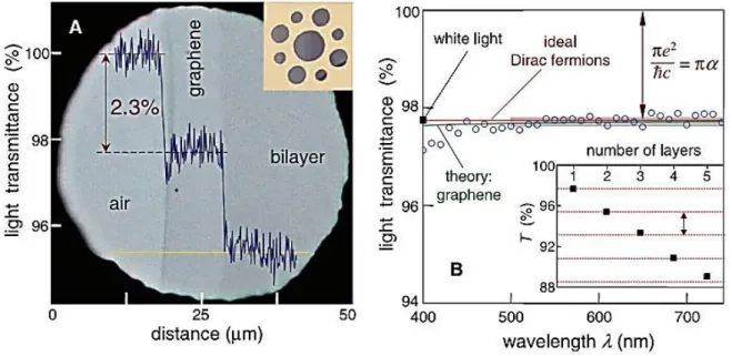
(35) Thèse de Amer Khudair Hussien Al-Nafiey, Lille 1, 2016. Besides, suspended graphene shows an ultra-high low-temperature mobility approaching 200 000 cm2V-1s-1 for carrier densities below 5 × 109 cm-2 [200].. 1.3.3.. Optical properties. Graphene's unique optical properties produce an unexpectedly high opacity for an atomic monolayer suspended in vacuum, with a measured white light absorbance of 2.3% and a negligible reflectance (<0.1%). Absorbance increases linearly with the layers number from 1 to 5 (Figure 1.9) [201, 202].. Figure 1.9: Looking through one-atom-thick crystal. (A) Photograph of a 50-μm aperture partially covered by graphene and its bilayer. The line scan profile shows the intensity of transmitted white light along the yellow line. (B) Transmittance spectrum of single-layer graphene (open circles). The red line is the transmittance T= (1+0.5πα)–2 expected for two dimensional Dirac fermions, whereas the green curve takes into account a nonlinearity and triangular warping of graphene’s electronic spectrum. (Inset) Transmittance of white light as a function of the number of graphene layers (squares) [202].. In addition, the optical transition can be modified by changing the Fermi energy considerably through electrical gating [203]. Another property of graphene is its photoluminescence (PL). It is possible to make graphene luminescent by inducing a suitable band gap. Two routes have been proposed. The first method involves cutting graphene into nanoribbons and quantum dots. 35 © 2016 Tous droits réservés.. doc.univ-lille1.fr.
(36) Thèse de Amer Khudair Hussien Al-Nafiey, Lille 1, 2016. The second one is a physical or chemical treatment with different gases to reduce the connectivity of the π electron network [4, 204]. For example it was shown that PL can be induced by oxygen plasma treatment of graphene single layer on silicon substrate covered with 100 nm SiO2 [205]. This gives an opportunity of making hybrid structures by etching just the top layer, while keeping the underlying layer unaffected. Broad PL from solid GO and liquid GO suspension was also observed. The progressive chemical reduction of GO into rGO quenched the PL, whereas oxidation increases PL by producing a disruption of the π network and opening a direct electronic band gap [206]. Fluorescent organic compounds are very important for the development of low cost optoelectronic devices [207]. Particularly blue fluorescence from aromatic or olefin molecules and their derivatives are important for display and lighting applications [208]. Blue PL was observed for GO thin films deposited from thoroughly exfoliated suspensions [209]. The PL characteristic and its dependence on the reduction of GO originate from the recombination of electron–hole pairs localized within small sp2 carbon clusters embedded within the GO sp3 matrix [209]. The exceptional electrical properties in conjunction with optical properties have fuelled lot of interests in novel photonic and optoelectronics devices [210-212]. Numerous promising applications using graphene have been suggested, including photodetectors, touch screens, light emitting devices, photovoltaics, transparent conductors, terahertz devices and optical limiters.. 1.3.4.. Mechanical properties. The mechanical properties of monolayer graphene membranes were measured based on nanoindentation using atomic force microscopy (AFM) [11]. Measurements have shown that graphene has a breaking strength of 42N m-1 which is over 100 times greater than a hypothetical steel film of the same thickness [5, 213]. The tensile modulus (stiffness) is 1 TPa (150,000,000 psi). The discussed experimental data on the Young modulus (E = 1 TPa) and the intrinsic strength (σ = 130 GPa) exhibited by pristine graphene are consistent with computer simulations [214], showing values of E = 1.05 TPa and σ = 110 GPa [215]. These values of E and σ are extremely large and make graphene to be very attractive for structural and other applications. This value. 36 © 2016 Tous droits réservés.. doc.univ-lille1.fr.
Figure
![Figure 1.1: Graphene can be considered as the mother material of buckyballs, carbon- carbon-nanotubes and graphite [7]](https://thumb-eu.123doks.com/thumbv2/123doknet/3736179.112156/13.892.161.687.390.838/figure-graphene-considered-mother-material-buckyballs-nanotubes-graphite.webp)
![Figure 1.6: The oxidation-exfoliation-reduction process used to generate individual sheets of chemical converted graphene from graphite [97]](https://thumb-eu.123doks.com/thumbv2/123doknet/3736179.112156/22.892.119.751.310.761/oxidation-exfoliation-reduction-generate-individual-chemical-converted-graphene.webp)
![Figure 1.8: Band structure of graphene. The conduction band touches the valence band at the K and K’ points [199]](https://thumb-eu.123doks.com/thumbv2/123doknet/3736179.112156/34.892.214.689.650.905/figure-band-structure-graphene-conduction-touches-valence-points.webp)
+7
![Figure 1.16: TGA plots of graphene, GO and rGO. rGO had better thermal stability than GO [273]](https://thumb-eu.123doks.com/thumbv2/123doknet/3736179.112156/47.892.156.732.202.606/figure-tga-plots-graphene-rgo-better-thermal-stability.webp)
![Figure 1.17: FTIR spectra of graphene, fresh graphene oxide and rGO [277].](https://thumb-eu.123doks.com/thumbv2/123doknet/3736179.112156/48.892.142.742.223.687/figure-ftir-spectra-graphene-fresh-graphene-oxide-and.webp)
Documents relatifs
