UNIVERSITÉ DE MONTRÉAL
CELLULOSE NANOFIBER-REINFORCED POLYMER BIOCOMPOSITES
FATEMEH SAFDARI SHADLOU DÉPARTEMENT DE GÉNIE CHIMIQUE ÉCOLE POLYTECHNIQUE DE MONTRÉAL
THÈSE PRÉSENTÉE EN VUE DE L'OBTENTION DU DIPLÔME DE PHILOSOPHIAE DOCTOR
(GÉNIE CHIMIQUE) AVRIL 2017
UNIVERSITÉ DE MONTRÉAL
ÉCOLE POLYTECHNIQUE DE MONTRÉAL
Cette thèse intitulée:
CELLULOSE NANOFIBER-REINFORCED POLYMER BIOCOMPOSITES
présentée par : SAFDARI SHADLOU Fatemeh
en vue de l'obtention du diplôme de : Philosophiae Doctor a été dûment acceptée par le jury d'examen constitué de :
M. LAFLEUR Pierre, Ph. D., président
M. CARREAU Pierre, Ph. D., membre et directeur de recherche
Mme HEUZEY Marie-Claude, Ph. D., membre et codirectrice de recherche M. KAMAL Musa, Ph. D., membre et codirecteur de recherche
M. AJJI Abdellah, Ph. D., membre
DEDICATION
ACKNOWLEDGMENTS
First of all, I wish to offer my heartfelt appreciation to my three supervisors, Professor Pierre J. Carreau, Professor Marie-Claude Heuzey, and Professor Musa R. Kamal. This thesis would not have been possible without their knowledge, patience, and, support. Their kind words always were indeed encouraging to advance more and more. The discussions I have had with them on scientific matters (and the matters beyond science) and the experiences I have gained, these are invaluable and not easily achievable, and so, it is my great honor to be a member of their research group. I also acknowledge Professor Mohini M. Sain from University of Toronto who kindly provided the cellulose nanofibers to perform this dissertation.
Besides, I would like to thank the thesis committee, Professor Pierre G. Lafleur, Professor Abdellah Ajji, and Professor Marianna Kontopoulou for accepting to evaluate this dissertation. My especial thanks are dedicated to Professor Hossein Nazockdast, my supervisor in Amirkabir University of Technology, who taught me great scientific and life lessons, and also, Professor Hormoz Eslami, who motivated me to continue my studies.
I am also grateful to technical and administrative staffs of Chemical Engineering Department, Evelyne Rousseau, Valerie Beaudart, Martine Lamarche, and especially, Melina Hamdine, our
ex-research associate, for her kind cooperation and encouragement during my first year of Ph.D. Many thanks to all the present (and the past) members of the Rheology Group who are truly kind and have generously shared their knowledge and experiences during the years of my Ph.D.
I also would like to convey my sincere appreciation to all my friends, in Iran and Canada, who have always supported and helped me in research, and more important, in life.
I owe gratitude to Teodora Gancheva for kindly translating the abstract of this thesis to French. Definitely, my accomplishments throughout my life would not have been achievable without unconditional love and support of my beloved parents and two sisters. I am also so proud to be the aunt of my lovely niece and nephew, who could make me smile even in the hardest time I have had during the years being far from. I apologize that I could not be there for you in important moments of your life. Know that I love you all so much; my life has been short in you, no matter where I am.
Finally, my deepest gratitude goes to my spouse, Davood, for overwhelming help, support, and forgiveness he provided so far; someone who has never left my side. I am just lucky to have a caring friend as you in my life. Thanks!
RÉSUMÉ
L'intérêt d'incorporer des nanofibres de cellulose (CNFs) comme agents de renforcement pour améliorer les propriétés des matrices polymères a considérablement augmenté dernièrement, compte tenu de l'origine biologique de ces nanoparticules ainsi que leurs bonnes propriétés physiques et mécaniques, comparées aux renforts inorganiques. Cependant, il existe des défis importants liés à leur grand facteur de forme, nature fibrillaire, flexibilité élevée et hydrophilicité qui rendent les CNFs fortement enchevêtrées, et qui compliquent leur dispersion/distribution dans les polymères, en particulier dans les matrices hydrophobes.
Cette thèse vise à développer des biocomposites polymères/CNF avec une microstructure bien dispersée et des propriétés améliorées. Nous avons choisi deux polymères qui nécessitent des améliorations au niveau de leurs propriétés thermomécaniques: le polylactide (PLA), qui est un polymère hydrophobe et d'origine biologique, et le poly(oxyde d'éthylène) (PEO), qui est un polymère hydrophile, biocompatible et biodégradable. Les biocomposites ont été préparés par des méthodes de mélange simple, soit en utilisant du N,N-diméthylformamide (DMF), soit en utilisant de l'eau comme solvant. À titre de comparaison, certains composites ont aussi été préparés à l'état fondu.
Des composites à haute performance comprenant du PLA et des CNFs (0,25–5% massique) ont été d'abord préparés par coulée de solvant sans aucune comptabilisation. La viscosité complexe et le module élastique des biocomposites PLA/CNF ont été augmentés jusqu'à deux et cinq ordres de grandeur, respectivement, à basses fréquences comparativement au PLA. Une amélioration jusqu'à 50% pour le module d'Young du PLA a été obtenue par incorporation des CNFs. De même, la résistance à la traction a été augmentée de 31%. Le module élastique en flexion dans l'analyse thermique mécanique dynamique (DMTA) a été augmenté jusqu'à 51 et 264% à température ambiante et 70 °C, respectivement. Une bonne transparence a été retenue pour les films biocomposites dans la plage de lumière visible, comparativement à celle du PLA.
La seconde partie de ce projet était liée à la préparation de biocomposites de PEO/CNF renforcés avec différents chargements de nanofibres, c'est-à-dire de 1 à 3% massique, par mélange en solution aqueuse. À basses fréquences, pour les biocomposites PEO/CNF, on a obtenu des augmentations allant jusqu'à deux et trois ordres de grandeur pour la viscosité complexe et le module élastique, respectivement, comparé au PEO seul. Le module d'Young et le module élastique en DMTA à
température ambiante ont été améliorés par environ 48% en ajoutant 3% massique de CNFs au PEO; la résistance à la traction a également augmenté de 35%. De plus, la transparence des films composites dans la plage de lumière visible était similaire à celle du film de PEO non chargé. Pour les biocomposites préparés à l'état fondu, les CNFs étaient mal dispersés et, par conséquence, aucune amélioration des propriétés n'a été observée.
Dans la dernière partie, un polyéthylène glycol (PEG) a été utilisé comme agent comptabilisant pour le système PLA/CNF. Initialement, un « masterbatch » CNF/PEG (rapport 1:2) a été préparé en solution aqueuse. Ensuite, les biocomposites ont été élaborés par la méthode de coulée de solvant. Différentes techniques microscopiques ont montré que les CNFs étaient mieux dispersées/distribuées dans le PLA lorsque l'agent comptabilisant était présent. La viscosité complexe et le module élastique de composites comptabilisés ont été augmentés d'un ordre de grandeur par rapport aux composites non compatibilisés. En utilisant un agent comptabilisant, les modules élastiques en DMTA du PLA contenant 2% massique de nanofibres, à température ambiante et à 80 °C, ont été augmentés jusqu'à 42 et 553%, respectivement, par rapport au PLA. L'effet de nucléation des CNFs sur la cristallisation du PLA était plus prononcé par rapport aux échantillons non compatibilisés. Aussi, une meilleure transmission de la lumière a été mesurée pour les films composites PLA/CNF/PEG par rapport aux films PLA/CNF. D'autre part, aucune amélioration des propriétés, par rapport à la matrice, n'a été observée pour les biocomposites préparés à l'état fondu.
En conclusion, la morphologie, la rhéologie, les propriétés mécaniques et les résultats de transmission de la lumière ont confirmé qu'en utilisant des méthodes de préparation en solution simples, une bonne dispersion et distribution des CNFs dans les matrices polymères PLA, PEO et PLA/PEG a été obtenue. Des améliorations substantielles des propriétés thermomécaniques des composites ont été constatées à faibles teneurs en nanofibres.
ABSTRACT
The interest to incorporate cellulose nanofibers (CNFs) as reinforcing agents to enhance the properties of polymer matrices has recently grown considerably, as these nanoparticles are bio-based and have good physical and mechanical properties, comparable to those of inorganic fillers. However, one faces important challenges associated with their large aspect ratio, fibrillated nature, high flexibility and hydrophilicity that make CNFs highly entangled, which render their dispersion/distribution in polymers quite difficult, especially in hydrophobic matrices.
This thesis aims at developing polymer/CNF biocomposites with well-dispersed microstructure and enhanced properties. We chose two polymers that need improvements in thermomechanical properties: polylactide (PLA), which is a commonly used bio-based hydrophobic polymer, and poly(ethylene oxide) (PEO), which is a biocompatible/biodegradable hydrophilic polymer. The biocomposites were prepared via simple mixing methods, either using N,N-dimethylformamide (DMF) or water as solvents. For comparison, some composites were prepared in the molten state. High-performance composites comprising PLA and CNFs (0.25–5 wt%) were first prepared via solvent casting without any compatibilization. The complex viscosity and storage modulus of the PLA/CNF biocomposites were increased by up to two and five orders of magnitude, respectively, at low frequencies compared to the neat PLA. An improvement of up to 50% for the Young modulus of PLA was achieved by incorporating CNFs. Similarly, the tensile strength was raised by 31%. The flexural storage modulus in dynamic mechanical thermal analysis (DMTA) was increased by up to 51 and 264% at room temperature and 70 °C, respectively. Good transparency was retained for the biocomposite films in the visible light range comparable to that of neat PLA. The second part of this project was related to the preparation of enhanced PEO/CNF biocomposites with different nanofiber loadings, i.e., 1–3 wt%, via aqueous solution mixing. At low frequencies, increases of up to two and three orders of magnitude were obtained for the complex viscosity and storage modulus, respectively, of PEO/CNF biocomposites relative to the neat PEO. The Young modulus and the room temperature DMTA storage modulus were improved by ca. 48% by adding 3 wt% CNFs to PEO; the tensile strength also increased by 35%. Moreover, the transparency of the composite films in the visible range was similar to that of the neat PEO film. For the melt-prepared biocomposites, however, the CNFs were poorly dispersed and consequently no property enhancement was observed.
In the last part, poly(ethylene glycol) (PEG) was used as a compatibilizer for the PLA/CNF system. Initially, a CNF/PEG masterbatch (ratio of 1/2) was prepared in an aqueous solution. Then, the biocomposites were prepared using a solvent-casting method. Different microscopic techniques showed that CNFs were better dispersed/distributed within PLA when the compatibilizer was employed. The complex viscosity and storage modulus were increased by one order of magnitude for the compatibilized composites compared to those of the uncompatibilized composites. With compatibilization, the DMTA storage moduli of the PLA containing 2 wt% nanofibers at room temperature and 80 °C were enhanced by up to 42 and 553%, respectively, compared to the neat PLA. The nucleation effect of the CNFs on PLA crystallization was more pronounced relative to the uncompatibilized samples. Also, better light transmittance was measured for the PLA/CNF/PEG composite films relative to the PLA/CNF composite films. On the other hand, no property enhancement, compared to the matrix, was observed for the biocomposites prepared in the melt.
In conclusion, the morphology, rheology, mechanical properties and light transmittance results confirmed that, using simple solution methods, good dispersion and distribution of CNFs within the host polymer matrices, PLA, PEO and PLA/PEG, was achieved. Substantial enhancements in the thermomechanical properties of the composites were obtained at low nanofiber contents.
TABLE OF CONTENTS
DEDICATION ... III ACKNOWLEDGMENTS ... IV RÉSUMÉ ... VI ABSTRACT ... VIII TABLE OF CONTENTS ... X LIST OF TABLES ... XIV LIST OF FIGURES ... XVICHAPTER 1 INTRODUCTION ... 1
CHAPTER 2 LITERATURE REVIEW ... 3
2.1 Overview ... 3
2.2 Cellulose nanofibers (CNFs) ... 3
2.3 Polylactide (PLA) ... 5
2.4 Poly(ethylene oxide) (PEO) ... 6
2.5 PLA/cellulose biocomposites ... 6
2.6 Compatibilized PLA/cellulose biocomposites ... 17
2.7 PEO/cellulose biocomposites ... 23
2.8 Summary ... 25
CHAPTER 3 OBJECTIVES ... 26
CHAPTER 4 ORGANIZATION OF THE ARTICLES ... 27
CHAPTER 5 ARTICLE 1 : RHEOLOGICAL, MECHANICAL, AND THERMAL PROPERTIES OF POLYLACTIDE/CELLULOSE NANOFIBER BIOCOMPOSITES ... 29
5.1 Abstract ... 30
5.3 Experimental section ... 33
5.3.1 Materials ... 33
5.3.2 Sample preparation ... 33
5.3.3 Characterization ... 34
5.4 Results and discussion ... 36
5.4.1 Scanning electron microscopy (SEM) ... 36
5.4.2 Rheology ... 36
5.4.3 Tensile properties ... 38
5.4.4 Dynamic mechanical thermal analysis (DMTA) ... 42
5.4.5 Differential scanning calorimetry (DSC) ... 44
5.4.6 Thermogravimetric analysis (TGA) ... 46
5.4.7 Optical properties ... 47
5.5 Concluding remarks ... 48
5.6 Acknowledgments ... 49
5.7 References ... 49
CHAPTER 6 ARTICLE 2 : ENHANCED PROPERTIES OF POLY(ETHYLENE OXIDE)/CELLULOSE NANOFIBER BIOCOMPOSITES ... 54
6.1 Abstract ... 55 6.2 Introduction ... 55 6.3 Experimental section ... 57 6.3.1 Materials ... 57 6.3.2 Sample preparation ... 57 6.3.3 Characterization ... 58
6.4 Results and discussion ... 60
6.4.2 Rheology ... 61 6.4.3 DSC ... 63 6.4.4 Tensile properties ... 64 6.4.5 DMTA ... 67 6.4.6 TGA ... 69 6.4.7 Optical properties ... 69 6.5 Concluding remarks ... 71 6.6 Acknowledgments ... 72 6.7 References ... 72
CHAPTER 7 ARTICLE 3 : EFFECTS OF POLY(ETHYLENE GLYCOL) ON THE MORPHOLOGY AND PROPERTIES OF BIOCOMPOSITES BASED ON POLYLACTIDE AND CELLULOSE NANOFIBERS ... 77
7.1 Abstract ... 78 7.2 Introduction ... 78 7.3 Experimental section ... 81 7.3.1 Materials ... 81 7.3.2 Sample preparation ... 81 7.3.3 Characterization ... 82
7.4 Results and discussion ... 84
7.4.1 SEM ... 84
7.4.2 Transmission electron microscopy (TEM) ... 85
7.4.3 Atomic force microscopy (AFM) ... 87
7.4.4 Rheology ... 88
7.4.5 TGA ... 91
7.4.7 Tensile properties ... 93 7.4.8 DMTA ... 95 7.4.9 Optical properties ... 96 7.5 Concluding remarks ... 97 7.6 Acknowledgments ... 98 7.7 References ... 98
CHAPTER 8 GENERAL DISCUSSION ... 105
CHAPTER 9 CONCLUSIONS AND RECOMMENDATIONS ... 107
9.1 Conclusions ... 107
9.2 Original contributions ... 110
9.3 Recommendations ... 110
LIST OF TABLES
Table 2.1: Tensile properties of PLA and PLA/5CMF [59]. ... 7
Table 2.2: The Young modulus and tensile strength for PLA and PLA/5HPN [14]. ... 7
Table 2.3: Tensile properties of the PLA/MFC composites [47]. ... 10
Table 2.4: Tensile properties of the PLA/CNF composites [10]. ... 11
Table 2.5: Tensile properties of the neat PLA and PLA/2CNF at 25 °C [60]. ... 13
Table 2.6: Results of DSC tests for PLA and PLA/5BCNF [49]. ... 14
Table 2.7: Tensile properties of PLA and its composite containing 5 wt% BCNFs [49]. ... 14
Table 2.8: DSC results of the first heating and cooling scans [8]. ... 15
Table 2.9: DMTA properties of the neat PLA and its composite with 2.5 wt% CMFs [19]. ... 15
Table 2.10: Tensile properties of neat PLA and PLA/10CNF samples [61]. ... 17
Table 2.11: Tensile properties of different samples [59]. ... 17
Table 2.12: Young’s modulus and tensile strength of PLA and its modified composite [14]. ... 18
Table 2.13: DSC results of various samples [49]. ... 19
Table 2.14: Tensile properties of different samples [49]. ... 19
Table 2.15: The results of tensile tests for various samples [61]. ... 20
Table 2.16: Tensile properties of PLA and PLA/5A-CNF [62]. ... 21
Table 2.17: DSC values for PLA and PLA/2.5APS-CNF samples [8]. ... 22
Table 2.18: Values of storage modulus at 25 and 80 °C extracted from DMTA [19]. ... 23
Table 2.19: Melting temperature and crystalline content of PEO and PEO/15CNF [54]. ... 23
Table 2.20: DSC results of the neat PEO and PEO/CNF composites [55]. ... 24
Table 2.21: The results of tensile tests for different PEO/CNF samples [55]. ... 24
Table 2.22: DSC properties of PEO/CNC composites [55]. ... 24
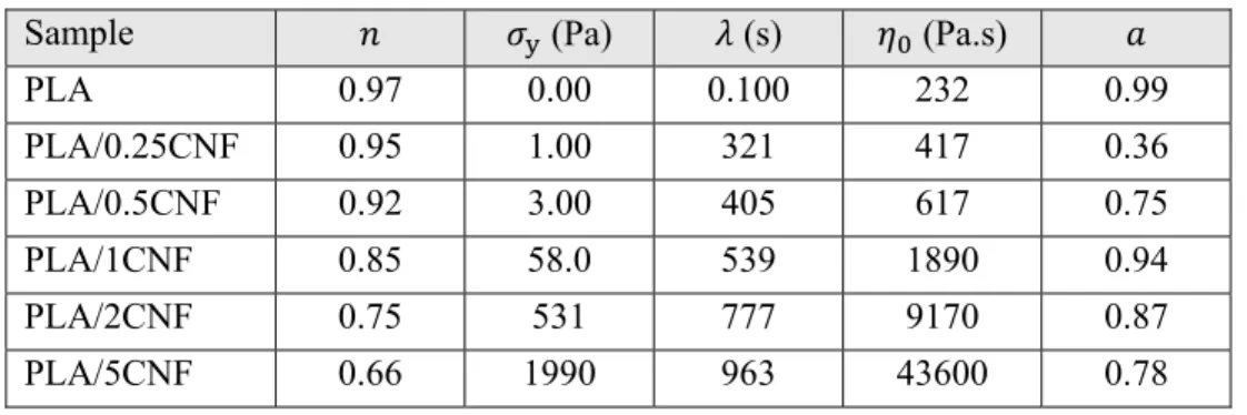
Table 5.1: Parameters of the modified Carreau-Yasuda model, Eq. 5.1. ... 38
Table 5.2: DSC results for first heating and first cooling sequences. ... 46
Table 6.1: Results of DSC tests for the first heating and cooling cycles. ... 64
Table 7.1: Modified Carreau-Yasuda model parameters, Eq. 7.1. ... 90
Table 7.2: DSC results of PEG and solution-prepared samples for first heating and cooling sequences. ... 93
LIST OF FIGURES
Figure 2.1: Chemical structure of cellulose molecule showing the AGU repeating unit [29, 30]. .. 3
Figure 2.2: Chemical structure of lactide (left), and PLA (right) [40]. ... 5
Figure 2.3: Chemical structure of ethylene oxide (left), and PEO (right) [51]. ... 6
Figure 2.4: SEM micrograph of the freeze-dried HPNs [14]. ... 7
Figure 2.5: SEM micrograph of MFC [11]. ... 8
Figure 2.6: SEM micrographs of the samples prepared in solution (left), and melt (right) with MFC concentration of 5 wt% [11]. ... 8
Figure 2.7: Stress-strain curves for the samples containing 5 wt% MFC prepared by solution and melt mixing methods (left), and solution-prepared samples containing different fiber contents (right) [11]. ... 9
Figure 2.8: Storage modulus vs temperature (left), and normalized storage modulus (right) for various PLA/MFC composites [47]. ... 10
Figure 2.9: AFM image of CNFs (left), and SEM micrograph of the fractured surface of PLA/5CNF composite (right) [10]. ... 11
Figure 2.10: Visual comparison of PLA/CNF composite films with different CNF contents [10]. ... 11
Figure 2.11: Tensile strength of PLA and PLA/1CNF composite [44]. ... 12
Figure 2.12: SEM micrograph of CNFs (left), and cryo-fractured surface of the composite containing 2 wt% CNFs (right) [60]. ... 12
Figure 2.13: DMTA properties of PLA and PLA/2CNF samples [60]. ... 13
Figure 2.14: AFM modulus images of PLA (left), and PLA/2.5CNF composite (right) at a scan size of 3 µm × 3 µm [8]. ... 15
Figure 2.15: SEM micrograph of CNFs [61]. ... 16
Figure 2.16: MFI results regarding the effect of 10 wt% CNFs on the flowability of PLA [61]. . 16
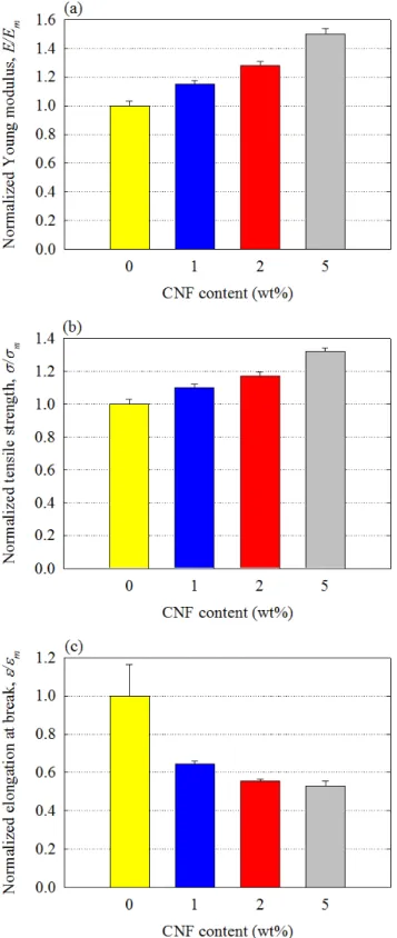
Figure 2.18: The results of tensile strength for various samples [44]. ... 19 Figure 2.19: Complex viscosity vs frequency at 180 °C for different samples [61]. ... 20 Figure 2.20: SEM micrographs of the fractured surface of PLA (left), and PLA/5A-CNF composite (right) [62]. ... 21 Figure 2.21: AFM modulus images of PLA (left), and PLA/2.5APS-CNF composite (right) at a scan size of 3 µm × 3 µm [8]. ... 22 Figure 2.22: TEM image of CNFs [55]. ... 23 Figure 5.1: SEM micrographs of (a) freeze-dried CNF aqueous suspension (0.1 wt%) and (b) PLA/2CNF. ... 36 Figure 5.2: Complex viscosity (a) and storage modulus (b) vs frequency for PLA and PLA/CNF composites at 175 °C and strain amplitude of 5%. The fits of the modified Carreau-Yasuda model, Eq. 5.1, are shown by the solid lines in (a). ... 38 Figure 5.3: Typical stress-strain curves behavior for different samples. ... 39 Figure 5.4: Normalized values of the Young modulus (a), tensile strength (b) and elongation at break (c) of the PLA and its composites with different CNF contents. ... 40 Figure 5.5: Comparison of the experimental data of the normalized Young’s modulus of the PLA/CNF composites and predictions of the modified Halpin-Tsai and Krenchel models, Eqs. 5.2, 5.4 and 5.7, respectively. ... 42 Figure 5.6: Storage modulus in flexion (a) and tan (b) of the PLA and its composites. ... 43 Figure 5.7: Normalized storage modulus in flexion at 25 °C (a) and 70 °C (b) for various samples.
... 44 Figure 5.8: DSC thermograms of first heating (a) and first cooling (b) sequences for all samples.
... 46 Figure 5.9: TGA (a) and DTG (b) curves of freeze-dried CNFs, PLA and PLA/5CNF. ... 47 Figure 5.10: Light transmittance of PLA and PLA/5CNF films. ... 48 Figure 6.1: SEM micrographs of (a) freeze-dried CNFs, (b and c) PEO/3CNF for two different samples, and (d) PEO/3CNF (M). ... 60
Figure 6.2: Plots of (a) complex viscosity, and (b) storage and loss moduli as functions of frequency at 85 °C and strain amplitude of 0.05 for solution-prepared samples. The solid lines in (a) represent the fits of the modified Carreau-Yasuda model, Eq. 6.1, for all samples. ... 62 Figure 6.3: Plots of (a) complex viscosity and (b) storage modulus as functions of frequency at 85 °C and strain amplitude of 0.05 for PEO and PEO/CNF composites containing 3 wt% CNFs prepared in both solution and melt. ... 63 Figure 6.4: Normalized Young’s modulus (a), tensile strength (b) and elongation at break (c) for PEO/CNF samples containing different CNF loadings prepared in both solution and melt. For the neat PEO values of 686.8 MPa, 15 MPa and 6.5% for the Young modulus, tensile strength and elongation at break, respectively, were obtained. ... 66 Figure 6.5: Predicted values based on the Halpin-Kardos model, Eq. 6.5 using two aspect ratios for the CNFs, and the experimental data for the normalized Young’s modulus of different composite samples. ... 67 Figure 6.6: Plots of (a) storage modulus and (b) tan of the neat PEO and PEO/CNF composites.
... 68 Figure 6.7: Normalized values of the storage modulus at 20 °C for various samples. The storage modulus of the neat PEO at 20 °C is 725.2 MPa. ... 68 Figure 6.8: Plots of (a) TGA and (b) DTG for freeze-dried CNFs, PEO and PEO/3CNF. ... 69 Figure 6.9: Light transmittance of PEO and PEO/3CNF films of 145 ± 18 µm thickness. ... 70 Figure 6.10: Visual comparison of (a) PEO, (b) PEO/3CNF, and (c) PEO/3CNF (M) films (thickness of 145 ± 18 µm). ... 70 Figure 7.1: SEM images of (a-c) freeze-dried CNFs, (d-f) PLA/2CNF and (g-i) PLA/2CNF/4PEG, taken from different samples and/or at different magnifications. ... 85 Figure 7.2: TEM images of (a) dried CNFs (from an aqueous suspension containing 0.5 wt% fibers), (b-e) PLA/2CNF and (f-i) PLA/2CNF/4PEG, taken from different samples and/or at different magnifications. ... 86 Figure 7.3: AFM images of (a and b) PLA/2CNF and (c-h) PLA/2CNF/4PEG, at different magnifications and for different modes of height, adhesion and modulus. Positive height,
negative adhesion, and positive modulus represent the nanofibers, e.g. the arrows in (f-h) indicate how a nanofiber or fiber bundle appears in different modes. ... 87 Figure 7.4: (a) Complex viscosity, and (b) storage and loss moduli (filled and open symbols, respectively) vs frequency at 175 °C and 0.05 strain amplitude for all solution-based samples. The solid lines in (a) represent the modified Carreau-Yasuda model fits, Eq. 7.1. ... 89 Figure 7.5: Complex viscosity vs frequency at 175 °C and 0.05 strain amplitude for the samples prepared in the melt. ... 90 Figure 7.6: TGA (a) and DTG (b) plots of samples prepared in solution. ... 91 Figure 7.7: Normalized values of tensile properties: Young’s modulus (a), tensile strength (b) and elongation at break (c) for the samples prepared in the solution and molten states. Subscript refers to the PLA with Young’s modulus, tensile strength and elongation at break of 2.96 GPa, 66.3 MPa and 4%, respectively. ... 94 Figure 7.8: Flexural storage modulus (a) and tan (b) of the solution-prepared samples. ... 95 Figure 7.9: Normalized flexural storage modulus at 25 °C (a) and 80 °C (b) for samples prepared in the solution state. ... 96 Figure 7.10: Light transmittance of PLA, PLA/2CNF and PLA/2CNF/4PEG films. ... 97
CHAPTER 1
INTRODUCTION
The overdependence on petroleum-based products (synthetic polymers, resins, etc.) in the past half-century has increased consistently. This has encouraged researchers to consider green materials, especially those based on cellulose, as possible alternatives. Cellulose fibers at the micro and nano scales are attractive as promising candidates for replacing non-biodegradable fillers in the production of environmentally friendly green products, such as biocomposites [1]. Cellulose nanofibers (CNFs) can be extracted from various sources by mechanical separation of fibers into smaller elementary constituents, which typically requires high energy input. However, chemical and/or enzymatic fiber pretreatments have been developed to overcome this problem [2-4]. Such new materials that are the subject of continuing research are commercially interesting due to the abundance of the sources in nature, high strength and stiffness, large aspect ratio and surface area, low density, biocompatibility and biodegradability [5-16].
CNFs offer a series of advantages compared to glass fibers that is the most common reinforcement, such as lower density, flexibility during processing, less abrasive machine wear, and also minimal health hazards [17]. Their use as reinforcing agents in thermoplastics, especially bio-derived polymers, has attracted great interest. Polylactide (PLA) is the frontrunner among different biopolymers [5] and has numerous applications, e.g. in the medical, packaging and automotive fields [8-10, 13, 18, 19]. On the other hand, poly(ethylene oxide) (PEO) is a biocompatible and biodegradable polymer [20] that has already found applications in the biomedical and electrochemical fields, and is used as hydrogel, flocculating agent, and rheology modifier [2, 20, 21]. However, both PLA and PEO suffer from deficiencies in mechanical and thermal properties. The incorporation of CNFs can improve the thermomechanical properties of PLA and PEO while maintaining their unique properties such as biocompatibility, biodegradability and film transparency [2, 7, 22, 23]. This would result in biodegradable and biocompatible products comprising components from renewable sources, all or in parts that open various application prospects.
Nanofibers with high aspect ratios and flexibility such as CNFs, have strong tendency to entangle and form agglomerates with a non-uniform state of dispersion in a polymer matrix. This is the result of strong hydrogen bond attraction between the fibers [8-11, 13, 14, 16, 19]. Besides, the insufficient adhesion between hydrophilic CNFs and hydrophobic polymer matrices, such as PLA
[24], may hamper the use of CNFs as reinforcement in such matrices. Therefore, to improve the compatibility between CNFs and non-polar polymers, either surface modification or the use of a compatibilizer may have to be proposed.
This thesis focuses on developing biocomposites based on both hydrophilic and hydrophobic matrices, e.g. PEO and PLA, reinforced with CNFs through efficient preparation methods that lead to enhanced properties. It also presents a promising approach to increase the compatibility between CNFs and PLA, as one of the most commonly used bioplastics [5], which results in further improving the mechanical and thermal properties of PLA/CNF composites. This route includes the use of a miscible compatibilizer with PLA, i.e., poly(ethylene glycol) (PEG) [25-28], which has a better affinity with CNFs compared to PLA.
The main contributions of the current project are found in three papers; the first and second have been published in the journals of Polymer Composites and Cellulose, respectively, and the third one has been accepted in Cellulose.
In this thesis, the following chapters are presented: Chapter 1: Introduction
Chapter 2: Literature review Chapter 3: Objectives
Chapter 4: Organization of the articles
Chapters 5 to 7: The three papers reporting the main results of this project Chapter 8: General discussion
CHAPTER 2
LITERATURE REVIEW
2.1 Overview
Composite preparation is one of the methods to produce materials with new and/or enhanced properties compared to neat matrices. In recent years, polymers derived from renewable resources have been considered as promising alternatives to petroleum-based polymers thanks to their biodegradability. They reduce environmental concerns about greenhouse gas emissions and pollution and our reliance on fossil resources that currently have raised challenges [5]. Therefore, the preparation of composites from fully bio-based components is more desirable over traditional composites to minimize environmental impacts. The term “biocomposites” refers to composite materials made of bio-based components, all or in parts. All three biocomposites prepared in this project comprise matrices such as bio-based, biodegradable, and biocompatible polylactide (PLA), and biodegradable and biocompatible poly(ethylene oxide) (PEO) in the presence of a bio-based reinforcement, i.e., cellulose nanofibers (CNFs). Also, poly(ethylene glycol) (PEG) is used as a compatibilizer for the PLA/CNF system.
CNFs have interesting mechanical and physical properties that make them a good alternative to mineral reinforcements. Therefore, in this research dissertation, we investigate the use of CNFs to improve the properties of two biodegradable and biocompatible polymers, namely PLA and PEO.
2.2 Cellulose nanofibers (CNFs)
Cellulose is a long linear chain carbohydrate polymer with a large number of hydroxyl groups, three per anhydroglucose (AGU), the repeating unit of the molecular structure of cellulose. The chemical structure of cellulose is presented in Figure 2.1.
Figure 2.1: Chemical structure of cellulose molecule showing the AGU repeating unit [29, 30].
1 2 3 46 5
Cellulose is a molecule that is flexible [31] and the presence of the hydroxyl groups forms intra- and inter-molecular hydrogen bonds, which allow the creation of a 3D structure [1]. It is considered as the most common organic polymer and is an almost endless raw material for the increasing demand for environmentally friendly and biocompatible products [31]. The most important source for cellulose is wood pulp (soft and hard). Cellulosic fibers have high tensile strength, as a result of their fibrillar structure and the large amounts of hydrogen bonds. Therefore, the structural element of a plant that bears the load in tensile mode is cellulose. Also, it can be isolated from other sources including cotton, algae, tunicates and even bacteria in which the main role of cellulose is to act as the reinforcement material [1]. Several processes such as mechanical and chemical pulping, homogenization, acid hydrolysis, steam explosion, and high-intensity ultrasonication have been used to extract highly purified nanofibers from cellulosic materials [1, 2]. Depending on what source cellulose is extracted from and the extraction method, cellulosic particles vary in characteristic size, aspect ratio, morphology, crystallinity, and crystal structure [1, 30].
The first successful isolation of cellulosic microfibrils/microfibers (CMFs) was reported in 1983 via a Gaulin laboratory homogenizer. Dilute slurries of cut cellulose fibers from softwood pulp were subjected to high shear forces to yield individualized CMFs. The resulting gels showed a significant increase in viscosity after several passes through the homogenizer. It should be mentioned that a completely homogeneous sample of single CMFs cannot be achieved and mechanical disintegration of pulps usually results in cellulose fibril bundles having diameters below 100 nm, which are called cellulose nanofibrils/nanofibers (CNFs) [1]. However, considering their characteristic size, CNFs may be sometimes found under other nomenclatures in the literature, e.g. CMFs and micro-fibrillated cellulose (MFC).
CNFs, with diameter in the nanometer scale, provide a high surface area that can result in a strong interaction between the fibrils and surrounding species, such as organic and polymeric compounds, and living cells [32]. Compared to some inorganic fillers, the main advantages of CNFs that make them an interesting choice to replace inorganic fillers are: renewable nature, non-food agricultural based economy, low energy consumption in their production, low density, high specific strength and modulus, relatively reactive surface, which can be used for grafting specific groups, high sound attenuation of resultant composites, comparatively easy processability due to their nonabrasive nature, which allows high filling levels, resulting in significant cost savings. Moreover, disposal issues are easier to resolve by the combustion of cellulosic particle-filled composites in comparison
with inorganic fillers systems. Therefore, the possibility of using CNFs in the plastics industry has received considerable interest, particularly for the fabrication of automotive parts [33, 34]. Other potential applications could be in aircraft, railways, irrigation systems, furniture industries, sports and leisure items [34, 35]. Some new applications for cellulosic particles are based on their biocompatibility and chirality that can be utilized for the immobilization of proteins, heparin and antibodies [32].
2.3
Polylactide (PLA)
Polylactide (PLA) is a bio-derived, semi-crystalline, thermoplastic polyester [36-39] that is nowadays commercially used in a number of industrial sectors. PLA is the product of the ring opening polymerization of lactide monomer. Figure 2.2 presents the chemical structures of lactide and PLA. Although, PLA has oxygen single and double bounds in its chemical structure, it is classified as a hydrophobic polymer [24], rarely as a partially-hydrophilic one.
Figure 2.2: Chemical structure of lactide (left), and PLA (right) [40].
PLA has glass transition and melting temperatures of 55–60 °C and 155–170 °C, respectively. It has interesting mechanical properties, such as high modulus and tensile strength at room temperature, UV stability, gloss, low toxicity, and is of moderate cost [2, 5, 7, 13, 37-39, 41-45]. In addition, its other unique properties such as biocompatibility and biodegradability make it the frontrunner among many other polymers. Biomedical, automotive and textile applications, in addition to electronics and packaging industries, as disposable bottles/bags, food containers and plastic utensils, are examples of different sectors for which PLA has already found considerable applications [8-10, 13, 18, 19, 38, 39, 46-49]. Moreover, it has relatively good processability in conventional industrial processing techniques used for polyolefins (i.e., extrusion, injection molding, film blowing and blow molding) [8-10, 18, 19, 46, 47]. However, major drawbacks limit its applications: slow crystallization [47] and low heat resistance (low stiffness at elevated temperatures) [2, 7, 36, 42, 44, 47]. To overcome these deficiencies, the use of reinforcements is a
possible route [2, 36]. However, appropriate reinforcements should be chosen to maintain PLA biocompatibility, biodegradability and film transparency. In this regard, some common nanofillers (e.g. carbon nanotubes) may not be appropriate due to the lack of biocompatibility, biodegradability, and gloss of the final composites.
2.4 Poly(ethylene oxide) (PEO)
Poly(ethylene oxide) (PEO) is another nontoxic, semi-crystalline, thermoplastic polymer that is highly hydrophilic [20, 21, 50]. Figure 2.3 presents the chemical structure of PEO that is the product of the ring opening polymerization of ethylene oxide monomer.
Figure 2.3: Chemical structure of ethylene oxide (left), and PEO (right) [51].
PEO has glass transition and melting temperatures of ca. -40 °C and 63–66 °C, respectively. It is worth mentioning that for molecular weights of 20,000 g/mol and lower the polymer with a similar chemical structure to PEO is referred as poly(ethylene glycol) (PEG) [52], which is the result of
polycondensation of ethylene glycol molecules. PEO has found applications in biomedical, energy storage [20, 21, 53-55], and the electrochemical field as electrolyte in lithium polymer cells [21, 56-58]. Other uses are hydrogel, dispersant, surfactant, flocculating agent and rheology modifier [2, 21]. However, its deficient mechanical and thermal properties and high crystallinity are drawbacks for many applications. Thermomechanical properties of PEO can also be improved by incorporating reinforcements. It is important to preserve its advantageous properties, such as high biocompatibility, biodegradability [2, 21, 54] and film transparency [22, 23].
2.5 PLA/cellulose biocomposites
Mathew et al. [59] investigated the effect of 5 wt% cellulose microfibers (CMFs), diameters up to 1 µm, on mechanical properties of PLA. The CMF aqueous suspension was pumped into the PLA melt stream during extrusion. Table 2.1 presents the results of a mechanical test for PLA and PLA/5CMF samples. The Young modulus of PLA increased by 30% for the composite; however, the tensile strength remained unchanged and the elongation at break decreased.
Table 2.1: Tensile properties of PLA and PLA/5CMF [59].
Sample Young’s modulus (GPa) Tensile strength (MPa) Elongation at break (%)
PLA 2.0 ± 0.2 58 ± 6 4.2 ± 0.6
PLA/5CMF 2.6 ± 0.1 58 ± 5 2.8 ± 0.5
They also prepared PLA composite containing 5 wt% cellulose nanocrystals (CNCs) of diameter of 10–15 nm and average aspect ratio of 40, with a similar preparation method to that of PLA/CMF composites [59], to compare the effect of the two cellulosic reinforcements on mechanical properties. The Young modulus of PLA increased by 20% in the presence of 5 wt% CNCs; however, the improvement was lower compared to the composite with the same content of CMFs (see Table 2.1). Moreover, the tensile strength of PLA slightly decreased by incorporating CNCs. Wang and Sain [14] freeze-dried hemp nanofibers (HPNs) and prepared a PLA composite containing 5 wt% fibers using an internal mixer in the molten state. In that study, the nanofibers had diameters between 50 and 100 nm and lengths in the micrometer scale. Figure 2.4 presents a scanning electron microscopy (SEM) micrograph of the freeze-dried HPNs.
Figure 2.4: SEM micrograph of the freeze-dried HPNs [14].
Table 2.2 reports the results of the tensile test for the neat PLA and PLA/5HPN. The Young modulus and tensile strength were negligibly increased for PLA containing 5 wt% HPNs, 3 and 5%, respectively, compared to those of the neat PLA.
Table 2.2: The Young modulus and tensile strength for PLA and PLA/5HPN [14]. Sample Young’s modulus (GPa) Tensile strength (MPa)
PLA 2.72 ± 0.09 65.49 ± 0.21
Iwatake et al. [11] prepared PLA reinforced with 3–20 wt% micro-fibrillated cellulose (MFC) via a solution preparation method using acetone. The suspensions were dried and finally the samples were kneaded by a twin rotary roller mixer in the molten state. For the sake of comparison one sample was prepared by direct mixing of MFC aqueous suspension, containing 10 wt% solids, into molten PLA using the same mixer. Figure 2.5 shows the SEM micrograph of MFC consisting of fibers with diameters of nanometer to submicron forming a web-like network.
Figure 2.5: SEM micrograph of MFC [11].
The micrographs of composites containing 5 wt% MFC prepared via solution and melt mixing are presented in Figure 2.6. A uniform dispersion was observed for the solution-based composite (Figure 2.6 left), while agglomerates remained in the composite prepared via melt mixing (Figure 2.6 right).
Figure 2.6: SEM micrographs of the samples prepared in solution (left), and melt (right) with MFC concentration of 5 wt% [11].
Figure 2.7 depicts tensile stress-strain curves for the neat PLA and samples containing 5 wt% MFC prepared using both preparation methods and solution-prepared composites with 3–20 wt% fibers.
The mechanical properties of PLA were improved for the solution-based sample over the melt-prepared sample with the same content of fibers, i.e., 5 wt% (Figure 2.7 left). The Young modulus and tensile strength were improved by 38 and 33%, respectively, for solution-based samples with the addition of MFC up to 10 wt%, and for larger concentrations they decreased (Figure 2.7 right).
Figure 2.7: Stress-strain curves for the samples containing 5 wt% MFC prepared by solution and melt mixing methods (left), and solution-prepared samples containing different fiber contents (right) [11].
Iwatake et al. [11] also prepared a sample containing 5 wt% bleached Kraft pulp of smooth surface with 30–50 µm in diameter, via the same preparation method described for solution-based PLA/MFC composites, to study the effect of fiber morphology. The Young modulus increased negligibly and the yield strain and the tensile strength were reduced by 30 and 15%, respectively, at a fiber content of 5 wt% compared to those of the neat PLA. However, these properties were improved in the presence of the same content of MFC (see Figure 2.7).
Suryanegara et al. [47] incorporated up to 20 wt% of MFC reinforcement into PLA using a solution method with dichloromethane, followed by drying and kneading using a twin rotary roller mixer in the molten state. Thereafter, they annealed the samples to prepare highly-crystalized composites. Table 2.3 presents the data of the tensile tests and Figure 2.8 reports the results of the storage modulus in dynamic mechanical thermal analysis (DMTA). The maximum enhancements were obtained at the highest MFC concentration, i.e., 20 wt%. The Young modulus and tensile strength of PLA increased by ca. 42 and 14%, respectively, while the elongation at break decreased (Table 2.3); the storage modulus at 20 and 80 °C improved by 37 and 220%, respectively, relative to the
PLA (Figure 2.8). However, more enhancements in tensile and DMTA properties of PLA were achieved when the samples were quenched in liquid nitrogen (amorphous state).
Table 2.3: Tensile properties of the PLA/MFC composites [47].
Sample Young’s modulus (GPa) Tensile strength (MPa) Elongation at break (%)
PLA 4.0 ± 0.1 60.9 ± 1.6 3.1 ± 0.4
PLA/3MFC 4.4 ± 0.1 63.6 ± 0.7 2.0 ± 0.1
PLA/5MFC 4.6 ± 0.1 64.4 ± 0.8 2.0 ± 0.1
PLA/10MFC 4.7 ± 0.1 66.2 ± 3.5 2.0 ± 0.2
PLA/20MFC 5.7 ± 0.1 69.4 ± 1.4 1.7 ± 0.1
Figure 2.8: Storage modulus vs temperature (left), and normalized storage modulus (right) for various PLA/MFC composites [47].
Jonoobi et al. [10] developed PLA/CNF composites via masterbatch preparation in a mixture of acetone and chloroform. The resulting masterbatch, after drying, was diluted with PLA using a twin-screw extruder to produce composites of 1–5 wt% CNFs. Figure 2.9 shows the atomic force microscopy (AFM) image of CNFs and the SEM micrograph of the fractured surface for the PLA/5CNF composite. The CNFs used in that study had diameters in the range from 40 to 70 nm (Figure 2.9 left), and the estimated length of several micrometers. However, agglomerates of ca. 10 µm size are evident in Figure 2.9 (right).
Figure 2.9: AFM image of CNFs (left), and SEM micrograph of the fractured surface of PLA/5CNF composite (right) [10].
A visual comparison of PLA/CNF composite films with different CNF contents is also presented in Figure 2.10. Large agglomerates (white spots) are observed in thin films, especially, as the CNF concentration increases.
Figure 2.10: Visual comparison of PLA/CNF composite films with different CNF contents [10].
The mechanical properties of the samples are reported in Table 2.4. The Young modulus and tensile strength of PLA increased by 24 and 21%, respectively, by incorporating 5 wt% CNFs; as expected, the elongation at break decreased.
Table 2.4: Tensile properties of the PLA/CNF composites [10].
Sample Young’s modulus (GPa) Tensile strength (MPa) Elongation at break (%)
PLA 2.9 ± 0.6 58.9 ± 0.5 3.4 ± 0.4
PLA/1CNF 3.3 ± 0.4 63.1 ± 0.9 2.8 ± 0.3
PLA/3CNF 3.4 ± 0.1 65.1 ± 0.6 2.7 ± 0.2
Qu et al. [44] also prepared a PLA/1CNF composite via a solvent-casting method using N,N-dimethylacetamide (DMAc) as the solvent. The CNFs were 50 nm wide and several micrometers long. Figure 2.11 presents the results of a tensile test. The tensile strength decreased from ca. 40 MPa for PLA to ca. 30 MPa for the PLA/1CNF.
Figure 2.11: Tensile strength of PLA and PLA/1CNF composite [44].
Kowalczyk et al. [60] employed a solution-based method in dichloromethane followed by drying and then melt mixing to prepare a PLA/CNF composite containing 2 wt% nanofibers. The CNFs employed in that investigation had the diameter and length of 200–300 nm and less than 300 µm, respectively. Figure 2.12 shows a SEM micrograph of the nanofibers and a micrograph of the cryo-fractured surface of PLA/2CNF. A good distribution of the CNFs within the PLA matrix was obtained (Figure 2.12 right).
Figure 2.12: SEM micrograph of CNFs (left), and cryo-fractured surface of the composite containing 2 wt% CNFs (right) [60].
Table 2.5 reports tensile properties at 25 °C. A decrease in the elongation at break and slight increases in the yield stress (5%) and the tensile strength (3%) were observed for PLA/2CNF compared to those of the neat PLA. However, the enhancement of the yield stress was more evident when the tensile test was performed at 55 °C.
Table 2.5: Tensile properties of the neat PLA and PLA/2CNF at 25 °C [60].
Sample Yield stress (MPa) Tensile strength (MPa) Elongation at break (%)
PLA 48.2 ± 1.1 46.9 ± 1.1 21 ± 6
PLA/2CNF 50.7 ± 1.5 48.2 ± 1.2 12 ± 3
Figure 2.13 presents the results of the DMTA test. The storage modulus of PLA at 20 °C increased by only 14% for PLA/2CNF. Moreover, the CNFs did not promote nucleation.
Figure 2.13: DMTA properties of PLA and PLA/2CNF samples [60].
Kowalczyk et al. [60] also prepared a sample containing 2 wt% cellulose fibers, with diameter in the range of 10–17 µm and length of less than 300 µm, to evaluate the effect of a significant increase of the size of cellulose fibers on the composite tensile properties at 25 °C. Reductions in both the yield stress and tensile strength of PLA in the presence of 2 wt% cellulose fibers were reported. However, these properties were increased in the presence of CNFs with a similar content (see Table 2.5).
Lee et al. [49] incorporated 5 wt% bacterial cellulose nanofibers (BCNFs) into PLA using 1,4-dioxane as the media for composite preparation. The suspension was then immersed in liquid nitrogen and subsequently dried via freeze-drying prior to injection molding. Table 2.6 reports the differential scanning calorimetry (DSC) data for the samples. The glass transition, , melting, , and crystallization, , temperatures of the matrix were reduced for the PLA/5BCNF, while the crystalline content, , of PLA increased.
Table 2.6: Results of DSC tests for PLA and PLA/5BCNF [49].
Sample (°C) (°C) (°C) (%)
PLA 63 ± 3 171 ± 2 113 ± 2 18 ± 2 PLA/5BCNF 58 ± 5 167 ± 2 89 ± 4 25 ± 5
Table 2.7 presents the results of mechanical tests for PLA and the PLA/5BCNF composite. The Young modulus of the composite was improved by 11%; however, its tensile strength decreased and the elongation at break remained unchanged compared to neat PLA.
Table 2.7: Tensile properties of PLA and its composite containing 5 wt% BCNFs [49]. Sample Young’s modulus (GPa) Tensile strength (MPa) Elongation at break (%)
PLA 4.08 ± 0.07 63.1 ± 2.0 1.7 ± 0.1
PLA/5BCNF 4.55 ± 0.03 57.8 ± 5.9 1.7 ± 0.2
Frone et al. [8] investigated the influence of CNFs, with diameters ranging from 11 to 44 nm, on the properties of PLA. To that end, a composite was produced via melt mixing of 2.5 wt% dried CNFs with PLA in an internal mixer. AFM images of PLA and PLA/2.5CNF are presented in Figure 2.14. The agglomerates (white-colored) are heterogeneously distributed in the composite sample (Figure 2.14 right).
Figure 2.14: AFM modulus images of PLA (left), and PLA/2.5CNF composite (right) at a scan size of 3 µm × 3 µm [8].
DSC results for the first heating and cooling scans are presented in Table 2.8. The CNFs were reported to act as nucleating agents as the cold-crystallization temperature, , decreased; however, the crystallization temperature decreased too. Also, a higher degree of crystallinity was achieved for the composite sample, whereas the glass transition and melting temperatures were not affected by the presence of the CNFs.
Table 2.8: DSC results of the first heating and cooling scans [8].
Sample (°C) (°C) (°C) (°C) (%)
PLA 56.9 87.3 168.1 104.3 38.9
PLA/2.5CNF 56.3 85.2 168.0 102.9 47.1
Frone et al. [19] also investigated the effect of adding cellulose microfibrils (CMFs), diameters ranging from 5 to 15 µm and aspect ratios from 8 to 14 [19], to PLA with the same fiber loading, i.e., 2.5 wt%, following the same processing procedure described in [8]. Table 2.9 presents the results of the storage modulus recorded from a DMTA test. The storage modulus at 25 °C increased by 18% for composite containing 2.5 wt% CMFs compared to that of PLA; however, the storage modulus at 80 °C decreased for that composite.
Table 2.9: DMTA properties of the neat PLA and its composite with 2.5 wt% CMFs [19]. Sample Storage modulus at 25 °C (GPa) Storage modulus at 80 °C (MPa)
PLA 3.4 ± 0.1 260 ± 10
Kiziltas et al. [61] reinforced PLA with 10 wt% CNFs using an internal batch mixer. The nanofibers had diameter and length of 10–500 nm and 1–10 µm, respectively. Figure 2.15 shows the SEM micrograph of the CNFs used in that investigation. The melt flow index (MFI) results are presented in Figure 2.16. The PLA/10CNF composite had a 65% lower MFI than that of PLA at temperature of the test.
Figure 2.15: SEM micrograph of CNFs [61].
Figure 2.16: MFI results regarding the effect of 10 wt% CNFs on the flowability of PLA [61].
The results of a tensile test are reported in Table 2.10. The Young modulus of PLA increased by 21% in the presence of 10 wt% CNFs; however, the tensile strength and elongation at break decreased.
Table 2.10: Tensile properties of neat PLA and PLA/10CNF samples [61].
Sample Young’s modulus (GPa) Tensile strength (MPa) Elongation at break (%)
PLA 2.98 ± 0.07 59.9 ± 1.3 2.40 ± 0.09
PLA/10CNF 3.60 ± 0.08 56.6 ± 0.9 1.78 ± 0.07
2.6 Compatibilized PLA/cellulose biocomposites
Mathew et al. [59] also developed CMF-reinforced PLA by adding PEG as a processing aid. A CMF/PEG aqueous suspension was pumped into PLA melt stream during extrusion, as described earlier. Table 2.11 reports the tensile properties of the samples. The tensile strength negligibly increased and the Young modulus increased by only 15% for the PLA/CMF/PEG composite containing 5 wt% fibers and 5 wt% PEG compared to the values of the neat PLA. Moreover, both properties were lower than for the uncompatibilized case (see Table 2.1). The elongation at break of PLA decreased for PLA/5CMF/5PEG composite (Table 2.11).
Table 2.11: Tensile properties of different samples [59].
Sample Young’s modulus (GPa) Tensile strength (MPa) Elongation at break (%)
PLA 2.0 ± 0.2 58 ± 6 4.2 ± 0.6
PLA/5CMF/5PEG 2.3 ± 0.1 59 ± 2 3.3 ± 0.2
Mathew et al. [59] produced a compatibilized PLA/5CNC composite, i.e., PLA/5CNC/5PEG, too. The Young modulus increased by only 5% compared to the PLA and the enhancement was lower compared to the PLA/5CMF/5PEG composite (see Table 2.11) and the PLA/5CNC composite; the tensile strength decreased by 19% compared to that of PLA.
Wang and Sain [14] modified HPNs using a styrene maleic anhydride copolymer (SMA) in aqueous suspension. The freeze-dried modified nanofibers were then used to produce a PLA composite with 5 wt% nanofibers via an internal batch mixer. SEM micrograph of the freeze-dried SMA-modified HPNs (SMA-HPNs) is presented in Figure 2.17 and the SEM micrograph of HPNs was presented earlier in Figure 2.4. They claimed that SMA could reduce the entanglements of the nanofibers. However, the dispersion of the modified nanofibers in PLA was not uniform and agglomerates were still evident.
Figure 2.17: SEM micrograph of the freeze-dried SMA-HPNs [14].
Table 2.12 reports the results of tensile tests for the neat PLA and modified composite. The Young modulus and tensile strength increased slightly by 10 and 9%, respectively, for the composite containing 5 wt% SMA-HPNs. Moreover, the enhancements were less in the case of unmodified composite (see Table 2.2).
Table 2.12: Young’s modulus and tensile strength of PLA and its modified composite [14]. Sample Young’s modulus (GPa) Tensile strength (MPa)
PLA 2.72 ± 0.09 65.49 ± 0.21
PLA/5SMA-HPN 2.99 ± 0.01 71.14 ± 0.64
Qu et al. [44] also prepared PLA/CNF composites containing 1 wt% nanofibers using DMAc as a solvent and PEG as a compatibilizer in a solvent-casting method. All the components were added into DMAc with CNF/PEG at a ratio of 3/2. Figure 2.18 depicts the results of the tensile strength for the samples. The tensile strength slightly increased from ca. 40 MPa for PLA to ca. 45 MPa for the PLA/CNF/PEG sample containing 1 wt% fibers.
Figure 2.18: The results of tensile strength for various samples [44].
Lee et al. [49] incorporated a bio-derived polylactide carbohydrate copolymer (Co) to compatibilize PLA/BCNFs containing 5 wt% nanofibers. They added PLA, freeze-dried CNFs and the copolymer into 1,4-dioxane. The suspension was then immersed in liquid nitrogen and subsequently dried via freeze-drying prior to injection molding. Table 2.13 presents the results of DSC tests performed for different samples. The glass transition, melting, and crystallization temperatures of the matrix were reduced for the composite containing 5 wt% BCNFs with 4.75 wt% Co, while the crystalline content of PLA increased in that sample.
Table 2.13: DSC results of various samples [49].
Sample (°C) (°C) (°C) (%)
PLA 63 ± 3 171 ± 2 113 ± 2 18 ± 2
PLA/5BCNF/4.75Co 57 ± 2 166 ± 6 87 ± 3 28 ± 2
Table 2.14 reports the results of the Young modulus and tensile strength of the PLA/5BCNF/4.75Co composite, which are shown to be improved by 15 and 7%, respectively, compared to PLA. The elongation at break of PLA also slightly increased by incorporating 5 wt% BCNFs with 4.75 wt% Co (Table 2.14).
Table 2.14: Tensile properties of different samples [49].
Sample Young’s modulus (GPa) Tensile strength (MPa) Elongation at break (%)
PLA 4.08 ± 0.07 63.1 ± 2.0 1.7 ± 0.1
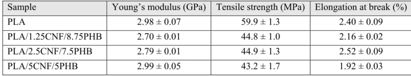
Kiziltas et al. [61] incorporated polyhydroxybutyrate (PHB) in order to compatibilize PLA/CNF composites containing 1.25–5 wt% nanofibers. A masterbatch of CNF aqueous suspension and PHB was prepared in an internal batch mixer; however, the ratio of CNFs to PHB was not kept constant that makes the results inconclusive. Thereafter, PLA/CNF/PHB composites were prepared by melt mixing of PLA and the dried masterbatch. Figure 2.19 presents the results of rheology measurements for the samples. Even the composite containing the largest CNF content, i.e., 5 wt%, showed similar complex viscosity as the neat PLA, probably due to the lack of a CNF network and possible matrix degradation.
Figure 2.19: Complex viscosity vs frequency at 180 °C for different samples [61].
Table 2.15 reports the results of the Young modulus, tensile strength and elongation at break for various samples. The Young modulus remained unchanged for the compatibilized composite with 5 wt% CNFs and decreased for lower concentrations relative to that of the neat PLA; the tensile strength and elongation at break of PLA decreased by incorporating CNFs and PHB.
Table 2.15: The results of tensile tests for various samples [61].
Sample Young’s modulus (GPa) Tensile strength (MPa) Elongation at break (%)
PLA 2.98 ± 0.07 59.9 ± 1.3 2.40 ± 0.09
PLA/1.25CNF/8.75PHB 2.70 ± 0.01 44.8 ± 1.0 2.16 ± 0.02 PLA/2.5CNF/7.5PHB 2.79 ± 0.01 44.9 ± 1.3 2.52 ± 0.09
PLA/5CNF/5PHB 2.99 ± 0.05 43.2 ± 1.7 1.92 ± 0.03
Jonoobi et al. [62] prepared acetylated CNFs (A-CNFs) to improve the properties of PLA. The nanofibers were acetylated in acetic anhydride and 5 wt% pyridine as catalyst. Thereafter, a
masterbatch of PLA/A-CNF was prepared in a mixture of acetone and chloroform and, after drying, it was diluted with PLA by extrusion (as described earlier in [10]). Figure 2.20 presents the SEM micrographs of PLA and PLA/5A-CNF composites. They reported that the dispersion/distribution of modified nanofibers in the matrix (Figure 2.20 right) was similar to that of the unmodified composite (see Figure 2.9 right).
Figure 2.20: SEM micrographs of the fractured surface of PLA (left), and PLA/5A-CNF composite (right) [62].
Table 2.16 reports the Young modulus, tensile strength, and elongation at break for the neat PLA and its modified composite containing 5 wt% A-CNFs. The Young modulus and tensile strength were increased compared to the neat PLA; however, the enhancements were lower in comparison with the unmodified composite at similar content of CNFs, i.e., PLA/5CNF (see Table 2.4). As expected, the elongation at break of PLA decreased for the PLA/5A-CNF composite (Table 2.16). Table 2.16: Tensile properties of PLA and PLA/5A-CNF [62].
Sample Young’s modulus (GPa) Tensile strength (MPa) Elongation at break (%)
PLA 2.9 ± 1.0 58 ± 0.5 3.4 ± 0.4
PLA/5A-CNF 3.5 ± 0.3 69 ± 0.6 2.9 ± 0.1
Frone et al. [8] investigated the influence of silane-modified CNFs on properties of PLA. To that end, a mixture of ethanol/water containing 3-aminopropyltriethoxysilane (APS) was added to a CNF aqueous suspension. Then, composites were prepared via melt mixing of dried modified CNFs with PLA using an internal mixer. Figure 2.21 shows AFM images of PLA and its compatibilized composite containing 2.5 wt% APS-modified CNFs (APS-CNFs). Better
dispersion/distribution of the APS-CNFs was observed in the matrix, as compared to the unmodified CNFs (see Figure 2.14).
Figure 2.21: AFM modulus images of PLA (left), and PLA/2.5APS-CNF composite (right) at a scan size of 3 µm × 3 µm [8].
Table 2.17 reports the results of DSC test for PLA and PLA/2.5APS-CNF samples. The CNFs were reported to slightly increase the degree of crystallinity of PLA. However, that increase was more evident for the composite containing unmodified CNFs (see Table 2.8) compared to the composites with APS-CNFs. Moreover, for compatibilized composite, the CNFs did not act as nucleating agent; the crystallization temperature decreased and the cold-crystallization temperature increased. The glass transition and melting temperatures of PLA remained unchanged.
Table 2.17: DSC values for PLA and PLA/2.5APS-CNF samples [8].
Sample (°C) (°C) (°C) (°C) (%)
PLA 56.9 87.3 168.1 104.3 38.9
PLA/2.5APS-CNF 57.2 89.8 167.9 101.1 41.1
Frone et al. [19] also investigated the effect of 2.5 wt% silane-modified CMFs on PLA properties with the same processing procedure described in [8]. Table 2.18 reports the results of the storage modulus from DMTA measurements. The storage modulus at 25 °C increased by 18% for the composites containing 2.5 wt% APS-CMFs compared to that of PLA; however, the storage modulus of that composite at 80 °C decreased. Similar changes to those of the compatibilized composite were observed for the uncompatibilized composite, i.e., PLA/2CMF, relative to those of the neat PLA (see Table 2.9).
Table 2.18: Values of storage modulus at 25 and 80 °C extracted from DMTA [19].
Sample Storage modulus at 25 °C (GPa) Storage modulus at 80 °C (MPa)
PLA 3.4 ± 0.1 260 ± 10
PLA/2.5APS-CMF 4.0 ± 0.1 240 ± 10
2.7 PEO/cellulose biocomposites
To prepare PEO/BCNF composites, Brown and Laborie [54] incorporated PEO in a culture medium of acetobacter xylinum (used for BCNF culture) to achieve finely dispersed nanofibers in PEO. Table 2.19 reports the data regarding DSC tests. No change in the melting temperature of PEO and a decrease in the crystalline content (from 67% for PEO to 49% for the PEO/15BCNF composite) are observed.
Table 2.19: Melting temperature and crystalline content of PEO and PEO/15CNF [54].
Sample (°C) (%)
PEO 68 ± 1 67 ± 1
PEO/15CNF 68 ± 3 49 ± 6
Xu et al. [55] prepared PEO/CNF composite films by solution casting. A CNF hydrogel was mixed with a PEO solution, allowing PEO molecules to penetrate in the CNF network. The nanofibers used in that investigation had an average width of 20 ± 14 nm and length of 1030 ± 334 nm (aspect ratio greater than 52). Figure 2.22 presents a transmission electron microscopy (TEM) image of the CNFs.
Table 2.20 reports the melting temperature and crystalline content of PEO and PEO/CNF composites. A 4 °C decrease in the melting temperature and a small decrease in the crystalline content of PEO (from 82 to 79%) by adding 4 wt% CNFs are observed.
Table 2.20: DSC results of the neat PEO and PEO/CNF composites [55].
Sample (°C) (%)
PEO 71.2 82
PEO/1CNF 70.7 74
PEO/4CNF 66.8 79
The results of tensile tests, Young’s modulus and yield strength, are reported in Table 2.21. A 31% enhancement in the Young modulus and a 46% improvement in the yield strength of PEO were reported in the presence of 4 wt% CNFs.
Table 2.21: The results of tensile tests for different PEO/CNF samples [55]. Sample Young’s modulus (MPa) Yield strength (MPa)
PEO 760 ± 109 14.2 ± 0.9
PEO/1CNF 896 ± 99 17.7 ± 0.9
PEO/4CNF 994 ± 222 20.8 ± 0.7
Xu et al. [55] also prepared composites of PEO and CNCs of diameter of 19 ± 5 nm and 151 ± 39 nm in length (aspect ratio of 8), with the same nanoparticle loadings to investigate the effect of fiber size. Table 2.22 reports the results of DSC measurements for composites based on PEO and CNCs. Both melting temperature and crystalline content are lower for the composites, regardless of CNC content, compared to those of the PEO (see Table 2.20).
Table 2.22: DSC properties of PEO/CNC composites [55].
Sample (°C) (%)
PEO/1CNC 66.9 77
PEO/4CNC 66.8 78
Tensile tests were also performed for PEO/CNC composites and the data are reported in Table 2.23. The Young modulus and yield strength of PEO increase with the CNC content; however,
PEO/4CNC exhibits a similar Young’s modulus as PEO/1CNF (see Table 2.21). This emphasizes the higher capacity of large-aspect ratio reinforcements, e.g. CNFs relative to CNCs, to improve the properties of polymer matrices.
Table 2.23: Results of tensile tests for different PEO/CNC samples [55]. Sample Young’s modulus (MPa) Yield strength (MPa)
PEO/1CNC 820 ± 195 15.9 ± 0.1
PEO/4CNC 895 ± 141 16.0 ± 0.8
2.8 Summary
Various approaches to try to disperse/distribute cellulosic reinforcements within the hydrophobic and hydrophilic matrices of PLA and PEO, respectively, and improve their thermomechanical properties have been reported. Also, compatibilization for the case of PLA/cellulose composites has been discussed. Not all the investigations were successful in preparing high-performance composites with low cellulose loadings, i.e., 1–5 wt%. Moreover, modification/compatibilization efforts to improve the properties of PLA/CNF composites were not completely successful. On the other hand, the effects of CNFs and their network structure on the rheological, thermomechanical, and optical properties of PLA/CNF and PEO/CNF systems have not been thoroughly investigated. Hence, the focus of this investigation is to explore the potential use of CNFs to enhance the properties of the two thermoplastics, i.e., PLA and PEO; it also attempts to employ rheology to investigate the effect of CNFs on the behavior of PLA and PEO in the molten state. CNFs are chosen in view of their superior characteristics, e.g. large aspect ratio and surface area, which may lead to higher property enhancement, if dispersed/distributed well in the host polymer matrices, compared to other types of cellulosic reinforcements from nanometer to micron size such as CNCs, CMFs, MFC, flax fibers, etc. On the other hand, the preparation of CNFs is much easier and safer and, definitely, more cost effective compared to CNCs, as it does not include an acid hydrolysis step. Moreover, in this dissertation the use of a compatibilizer, i.e., PEG, with the aim of preparing PLA/CNF composites with improved dispersion/distribution and properties is investigated. The next chapter is dedicated to the statement of the main and specific objectives of this work.
CHAPTER 3
OBJECTIVES
Taking into account the importance of the use of renewable and bio-based alternatives to petroleum-based components in order to reduce dependency on fossil fuels and decrease ecological footprints, the main objective of this thesis is to develop high-performance polymer biocomposites reinforced with cellulose nanofibers (CNFs).
To achieve the main objective, two thermoplastic polymer matrices are used: polylactide (PLA) and poly(ethylene oxide) (PEO), and the specific objectives are defined as:
1. To enhance the thermomechanical properties, e.g. heat resistance and crystallinity, of PLA by incorporating CNFs without using a compatibilizer.
2. To improve the thermomechanical properties, e.g. modulus and strength, of PEO by the addition of CNFs, comparing solution and melt preparation methods.
3. To further enhance the dispersion/distribution of nanofibers in PLA/CNF composites in the presence of a miscible compatibilizer, i.e., poly(ethylene glycol) (PEG). Two different preparation methods, solution and melt, to develop PLA/CNF/PEG biocomposites with improved thermal and mechanical properties are studied.
CHAPTER 4
ORGANIZATION OF THE ARTICLES
The main results from this research project are presented in the form of three scientific papers in the following chapters, 5, 6 and 7:
Chapter 5 presents the paper “Rheological, mechanical, and thermal properties of polylactide/cellulose nanofiber biocomposites” that has been published in Polymer Composites, 2015 impact factor: 2.0 (DOI 10.1002/pc.24127).
This chapter reports the development of polylactide (PLA)/cellulose nanofiber (CNF) biocomposites via a solution technique that results in well dispersed/distributed CNFs without the use of a compatibilizer. The biocomposites are characterized in terms of morphology and rheological, mechanical, thermal, and optical properties to investigate the effects of the CNFs on different properties of PLA.
Chapter 6 reports the paper “Enhanced properties of poly(ethylene oxide)/cellulose nanofiber biocomposites” that has been published in Cellulose, 2015 impact factor: 3.2 (DOI 10.1007/s10570-016-1137-1).
The preparation of poly(ethylene oxide) (PEO)/CNF biocomposites using a simple aqueous solution method is investigated to disperse/distribute nanofibers in PEO. This chapter also compares the efficiency of two different preparation methods, i.e., solution and melt, on PEO/CNF composite properties. The effects of the CNFs on rheological, mechanical, thermal, and optical properties of PEO are studied, as well.
The better dispersion of CNFs in PEO (Chapter 6) compared to PLA (Chapter 5) inspired us to study the use of poly(ethylene glycol) (PEG), a low molecular weight PEO, as a miscible compatibilizer in PLA/CNF system. Hence, Chapter 7 presents the paper entitled “Effects of poly(ethylene glycol) on the morphology and properties of biocomposites based on polylactide and cellulose nanofibers” that has been accepted in Cellulose.
This chapter aims at further dispersing/distributing the nanofibers in the PLA/CNF composites from Chapter 5 using PEG in order to promote the thermomechanical properties of PLA. A masterbatch of PEG and CNFs is prepared via a simple aqueous solution technique, and, two different preparation methods, i.e., solution and melt, are employed to prepare the biocomposites.
Then, the effects of PEG-compatibilized CNFs on the morphological, rheological, thermal, mechanical, and optical properties of PLA/CNF composites are studied.
![Figure 2.7: Stress-strain curves for the samples containing 5 wt% MFC prepared by solution and melt mixing methods (left), and solution-prepared samples containing different fiber contents (right) [11]](https://thumb-eu.123doks.com/thumbv2/123doknet/2346903.35102/28.918.108.810.237.493/containing-prepared-solution-solution-prepared-containing-different-contents.webp)
![Table 2.3: Tensile properties of the PLA/MFC composites [47].](https://thumb-eu.123doks.com/thumbv2/123doknet/2346903.35102/29.918.106.810.211.650/table-tensile-properties-pla-mfc-composites.webp)
![Table 2.4: Tensile properties of the PLA/CNF composites [10].](https://thumb-eu.123doks.com/thumbv2/123doknet/2346903.35102/30.918.137.784.880.1010/table-tensile-properties-pla-cnf-composites.webp)
![Table 2.5: Tensile properties of the neat PLA and PLA/2CNF at 25 °C [60].](https://thumb-eu.123doks.com/thumbv2/123doknet/2346903.35102/32.918.283.636.474.794/table-tensile-properties-neat-pla-pla-cnf-c.webp)
![Figure 2.16: MFI results regarding the effect of 10 wt% CNFs on the flowability of PLA [61]](https://thumb-eu.123doks.com/thumbv2/123doknet/2346903.35102/35.918.355.557.585.839/figure-mfi-results-regarding-effect-cnfs-flowability-pla.webp)
![Table 2.10: Tensile properties of neat PLA and PLA/10CNF samples [61].](https://thumb-eu.123doks.com/thumbv2/123doknet/2346903.35102/36.918.130.789.144.223/table-tensile-properties-neat-pla-pla-cnf-samples.webp)
![Table 2.18: Values of storage modulus at 25 and 80 °C extracted from DMTA [19].](https://thumb-eu.123doks.com/thumbv2/123doknet/2346903.35102/42.918.139.778.144.224/table-values-storage-modulus-c-extracted-dmta.webp)