Proceedings of the ASME 2013 International Design Engineering Technical Conferences & Computers and Information in Engineering Conference IDETC/CIE 2013 August 4-7, 2013, Portland, Oregon, USA
DETC2013-13469
CONTACT MODEL BETWEEN SUPERELEMENTS IN DYNAMIC MULTIBODY
SYSTEMS
Geoffrey Virlez∗ Olivier Br ¨uls Valentin Sonneville Emmanuel Tromme Pierre Duysinx Michel G ´eradinDepartment of Aerospace and Mechanical Engineering (LTAS) University of Li `ege
Chemin des chevreuils, 1, B52/3, 4000 Li `ege Belgium
Email: [email protected]
ABSTRACT
In this paper, a new contact formulation defined between flexible bodies modeled as superelements is investigated. Un-like rigid contact models, this approach enables to study the de-formation and vibration phenomena induced by hard contacts. Compared with full-scale finite element models of flexible bod-ies, the proposed method is computationally more efficient, espe-cially in case of a large number of bodies and contact conditions. The compliance of each body is described using a reduced-order elastic model which is defined in a corotational frame that fol-lows the gross motion of the body. The basis used to reduce the initial finite element model relies on the Craig-Bampton method which uses both static boundary modes and internal vibration modes. The formulation of the contact condition couples all de-grees of freedom of the reduced model in a nonlinear way. The relevance of the approach is demonstrated by simulation results first on a simple example, and then on a gear pair model.
∗Address all correspondence to this author.
INTRODUCTION
Often, contact models used for dynamic simulations of multibody systems are defined between rigid bodies. Various ap-proaches are available to formulate the contact condition such as the continuous contact modeling [1] or the nonsmooth contact dynamics method [2]. These contact models are efficient to rep-resent the interactions between bodies in large and complex me-chanical systems. Their formulation is often compact and does not require large computer resources if the number of bodies is small. However, due to the rigidity assumption, it is not possible to study the wave propagation caused by hard contacts or im-pacts, so that the dynamic responses may be unrealistic. Refer-ence [3] points out that for compliant gear bodies the flexibility effects modify significantly the contact forces applied on teeth and the motion of the whole gear pair system. With rigid body models, this kind of dynamic behavior can not be reproduced.
An accurate way to account for flexibility effects in contact situations is to rely on finite element models of bodies since this approach allows a reliable description of deformation and vibra-tion phenomena (see Ref. [4]). Nevertheless, if the number of bodies and the number of contact conditions are large, the
nu-merical simulation can become computationally inefficient with large computational time and huge memory requirements. For example, in order to model the contact between gear pairs, a very fine mesh of the whole skin of the two rotating wheels would be required, which would be quite expensive for a global dynamic analysis [5].
A contact model at an intermediate detail level between the two aforementioned categories is needed to simulate quickly and properly the contacts included in multibody models of industrial applications where the flexibility effects are not negligible.
The contact formulation presented in this paper is defined between two flexible bodies modeled as superelements. One ma-jor originality of the present work addresses the determination of the spatial configuration of the potential contact zones from the superelement variables. The contact forces computed in the 3D space are reformulated to load directly the superelement vari-ables. This approach allows very compact models of contacting bodies.
With the superelement method, the flexibility of each body is described using an elastic reduced order model which is de-fined in a corotational frame that follows the gross motion of the body. In this substructuring technique, the basis used to re-duce the initial finite element model relies on the Craig-Bampton method which computes both static modes related to the bound-ary nodes and vibration modes related to the internal nodes (see Ref. [6]).
For systems with wide potential contact zones or with sev-eral sliding contact paths, the size of the reduced model would still be rather large if each potential contact node has to be re-tained. For instance, in the model of a gear pair, all the nodes on the teeth flanks can enter in contact during the gear mesh. In the formulation developed in this work, in order to keep the model compact, all the candidate contact nodes do not necessarily have to be included in the set of boundary nodes. Only a couple of nodes, not compulsorily located on the contact zone, has to be selected as boundary nodes, so that a large number of nodes of the skin can still be condensed. The implementation is carried out with absolute nodal coordinates which are well suited with the superelement formulation described in Ref. [7].
At each time step, according to the component mode synthe-sis, the 3D topology of candidate contact zones is reconstructed from the generalized coordinates of the superelement (position and orientation of the corotational frame, positions of the bound-ary nodes, internal variables) and the global shape function of static and dynamic modes. From the absolute positions of the candidate contact node, a node-to-face projection algorithm is used to detect the active contact zone. The contact forces are evaluated by a contact law based on a penalty method with stiff-ness and damping contributions. Then, these contact forces are transferred to all coordinates of the reduced model in a nonlinear way.
In the sequel of this paper, the superelement formulation as
well as the corotational frame definition used in this study are briefly presented. Then, the various steps of the contact detection algorithm will be looked over. The contact law and the expres-sion of the contact forces are described next. Finally, the rele-vance of the approach for the dynamic analysis of transmission devices is demonstrated through simulation results of a simpli-fied example first, and then on a gear pair model.
EQUATIONS OF MOTION IN DYNAMICS
Using absolute nodal coordinates, the system configuration is represented with respect to a unique inertial frame. The dy-namics of a system including holonomic bilateral constraints is described by Eqn. (1-2),
M(q) ¨q + g(q, ˙q,t) +ΦTq(pΦ + kλ) = 0 (1)
kΦ(q,t) = 0 (2)
where q, ˙q and ¨q are the generalized displacements, veloc-ities and acceleration coordinates, M(q) is the mass matrix, g(q, ˙q,t) = ggyr(q, ˙q) + gint(q, ˙q)− gext(t) is a global forces
vec-tor where ggyrstates for the vector of the complementary inertia forces, gint(q, ˙q) the vector of the internal forces, e.g. contact, elastic and dissipation forces, and gext(t) the vector of the ex-ternal forces. According to the augmented Lagrangian method, the constraint forces are formulated byΦTq(pΦ+kλ) whereλis the vector of Lagrange multipliers related to algebraic constraints Φ = 0; k and p are respectively a scaling and a penalty factor to improve the numerical conditioning.
Equations (1-2) form a system of nonlinear differential-algebraic equations. The solution is evaluated step by step using a generalizedα-method which is a second order accurate time integration scheme (see [8], [9]). At each time step, a system of nonlinear algebraic equations has to be solved using a Newton-Raphson iteration process.
SUPERELEMENT DESCRIPTION
The superelement technique adopted in this work relies upon a nonlinear corotational formulation of a reduced-order model. In case of large amplitude motions of dynamic multibody sys-tems but undergoing only small strains, the only nonlinearities result from geometric effects generated by large displacements. In a local frame (floating [10] or corotational [11]) that follows the gross motion of the flexible body, a simple linear elastic model can thus be used to compute the elastic forces if the as-sumption of small strains is adequate.
The position xPand the rotation matrix RPof each node P of
absolute inertial frame corotational xP x0 XP uP P frame
FIGURE 1. KINEMATICS OF A SUPERELEMENT.
as (see Fig 1):
xP= x0+ R0(XP+ uP) (3)
RP= R0R(γP) (4)
where x0is the absolute position of the local reference frame,
R0 is the rotation matrix of the local frame about the inertial
frame, XP is the undeformed position of P in the local frame,
uPis its small elastic displacement in translation measured in the
local frame andγPis a set of parameters that represents the small
relative rotation with respect to the local frame.
The Craig-Bampton method is used to reduce the order of the linear elastic model and therefore to decrease the number of degrees of freedom of the initial finite element model. The basis of this substructuring technique is to use by both static boundary modes and internal vibration modes as ingredients of the com-ponent mode synthesis (see Ref. [6]). This association of modes allows to represent both the local deformations due to the forces applied on the boundary nodes and the global deformations in-volved by the dynamic behavior of the flexible body. The full set of modes is collected in the matrixΨ defined by:
Ψ =[ΨBΨI
]
(5)
whereΨBare the static boundary modes which can be considered
as the static deformations obtained when unit displacements are imposed successively on each interface degree of freedom; ΨI
are the internal modes related to the eigenmodes of the structure when the boundary nodes are clamped.
The reduced stiffness and mass matrices associated to the
superelement are given by:
K =ΨTKΨ (6)
M =ΨTMΨ (7)
where K and M are the stiffness and mass matrices of the finite element mesh before the model reduction.
{ u γ }
=Ψη (8)
The reduction relationship (Eqn. 8) enables to accurately expand the full vector of nodal elastic displacements in the local frame ({uT γT}T ) in terms of a few global shape functions (Ψ) and the vector of local coordinates (η) of the superelement expressed in the corotational frame. The latter is defined by:
η= uB γB ηI (9)
where uB,γBare the local displacement amplitude in translation
and rotation of the interface nodes;ηIare the modal amplitudes
of the internal modes.
The superlement formulation presented in this section is in-spired from Ref. [7]. However, in contrast to this reference, the position x0 and rotation variables α0 of the corotational frame
are included explicitly in the set q of generalized coordinates of the superelement: q = x0 α0 xB αB ηI (10)
where xB are the global nodal positions andαBare the global
nodal rotation parameters of the boundary nodes. This approach introduces 6 additional variables (x0,α0) in the set of
general-ized coordinates of the system and therefore increases the size of the equations of motion. But this allows to simplify some expressions, specially in the contact condition formulation and the definition of the corotational frame as it will be shown in the next Sections. A parametrization of spherical motion is used as in Ref. [7].
The elastic forces in the absolute frame are expressed as: gelastic= PTKη (11)
where P is a kinematic tangent matrix between infinitesimal vari-ations of local coordinatesηand absolute coordinates q:
δη= P(q)δq (12)
For the sake of conciseness the explicit expression of the inertia and gyroscopic forces and their linearized form will not be given in this paper but can be easily derived from [6].
COROTATIONAL FRAME DEFINITION
A corotational frame is attached to each body modeled by a superelement and follows its gross motion. This local frame is represented by the translation vector x0of the frame origin and
the rotation matrix R0which depends on the rotation variables
α0and gives the orientation of the local frame about the
iner-tial frame. Several formulations are available to determine the corotational frame. The simplest way consists in defining a refer-ence frame that follows the translation and rotation of a selected boundary node. However, with this method the mechanical re-sponse of the superelement can depend on the chosen boundary node. In [11], the position and orientation of the local frame is obtained by a weighted mean of positions and orientations of boundary nodes. The drawback of this formulation results from complex relations between global and local variables involving the multiplication of larges matrices.
The corotational frame definition used in this work requires that the frame variables x0,α0are independent variables and
in-cluded in the set q of generalized coordinates of the superelement (Eqn. 10). A set of 6 kinematic constraints is needed to link these local frame variables to the boundary node coordinates.
The boundary node displacements (uB,γB) expressed in the
corotational frame depend on the corotational frame variables (x0,α0). Small variations of (x0,α0) are equivalent to add a small
rigid body motion to the relative displacements and rotations. The aim of the constraints (Eqn. 13) is to minimize the part de-pending on the rigid body motion in the boundary node displace-ments. To reach this objective, the product of the rigid body motion defined in the corotational frame (τrig) by the relative
dis-placements and rotations (ηB) should be equal to zero. The part
of the reduced mass matrix related to the boundary nodes (MB)
is inserted as scaling factor of the various boundary nodes.
Φ(q) ≡τT
rigMBηB(q) = 0 (13)
The matrix of the 6 rigid body modes in the corotational frame is
given by: τrig= τrig,1 .. . τrig,i .. . τrig,nb (14)
where each matrixτrig,iis related to the ithboundary node:
τrig,i= [ I3×3 −eXBi 03×3 I3×3 ] (15)
The first column represents the boundary modes in translation and the second column, the modes in rotation. The skew-symmetric matrixea formed with the components of the vector a is used to replace cross products by matrix products (a×b = ea b). The corotational frame variables (x0,α0) do not appear
ex-plicitly in the constraint formulation (Eqn. 13), but the depen-dence with these variables is included in the definition of the local displacement vector (ηB) according to inverse expressions
of Eqn. (3-4).
Unlike both corotational frame formulations mentioned pre-viously, the superelement frame can be defined even when the boundary nodes have no rotational degrees of freedom, as it is the case if the initial finite element model is meshed with volume finite elements. With these kinematic constraints, at equilibrium the values given to x0and R0can be interpreted as the position
and orientation of the center of gravity of the body. In addition to x0andα0six more unknowns, the Lagrange multipliers, are
added for each superelement.
CONTACT DETECTION ALGORITHM
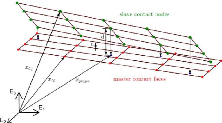
In order to determine the presence or absence of contact for each point of candidate contact areas, a contact detection al-gorithm based on a standard node-to-face projection method is used. The goal of this search procedure is to find the nodes of the slave body in contact with the element faces of the master body (see Fig. 2) .
The contact detection algorithm used in this work is suit-able for master triangular surface and can be summarized by the following steps (Fig. 3):
• Computation of the absolute positions xCi, xNi of the can-didate contact nodes respectively on slave and master body. If the contact nodes are retained as superelement boundary nodes, their position vectors are available in the vector q of generalized coordinates. However, in case of a large number
of potential contact nodes the size of the superelement ma-trices could not be drastically reduce compared with initial finite element model. The solution adopted in this study to keep a compact superelement model, consists in computing the absolute position of the candidate nodes at each itera-tion according to Equaitera-tions (3) and (8). In this way, only a few boundary nodes per superelement are needed and the accuracy of contact node positions computed depends on the detail level provided by the reduction basis (Ψ).
The candidate contact nodes are a fixed set of nodes located on the skin of the non-reduced model. These nodes are se-lected by the model analyst during the model construction and their absolute positions is computed at each simulation time step.
• For each master contact face, determination of the normal direction.
• Computation of the normal distance between each slave node and the plane of each master surface.
• Computation of the absolute coordinates of the projection point of the slave node onto the master face plane. This step is only carried out if the normal distance of this pair is negative.
• Determination of the projection point position in the surface element. The barycentric coordinates are used to determine whether if the projection point is inside or outside the sur-face element. This operation is only achieved if the node projected lies in the neighbourhood of the contact element. The contact is active if the projection point is inside the master element face and the normal distance between the slave node and the master face is negative.
A similar contact detection procedure is described in Ref. [3] for non-triangular faces on the master body. Nevertheless, this method involves nonlinear relations and therefore needs a Newton-Raphson iteration scheme to detect the active contact nodes.
With a node-to-surface projection approach, it is often rec-ommended that the mesh in contact zones is finer for the slave body than for the master body. It allows avoiding unreliable ef-fective contact zones and numerical problems which can affect the robustness of the numerical simulation.
CONTACT LAW
For each superelement point in contact, the magnitude of the contact force is computed with a penalty method depending on the penetration length ℓ of the slave node inside the master face. In addition to the stiffness term, this contact law (Eqn. 16) also includes a hysteresis damping term which enables to represent the kinetic energy loss in case of impact phenomena. In order to avoid a jump at the beginning of the contact and tension force at the end, the classical viscous damping term c ˙ℓ has been
multi-E1 E3
E2 xCi
master contact faces slave contact nodes
n d
xprojec xNi
FIGURE 2. PROJECTION OF SLAVE NODES ON MASTER
FACES.
FIGURE 3. FLOW CHART OF THE CONTACT DETECTION
AL-GORITHM.
plied by ℓ.
The contact law is expressed as:
f (ℓ, ˙ℓ) = {
kpℓ + c ℓ ˙ℓ if ℓ > 0 active contact
0 if ℓ < 0 no contact (16)
where kpis the contact stiffness, also called penalty parameter
and c is the damping coefficient. The penetration length ℓ and the penetration velocity ˙ℓ in the normal direction are computed according to the following expressions:
ℓ = nT(xN1− xCi) (17)
˙
ℓ = nT(˙xN1− ˙xCi) + (xN1− xCi)
T n˙ (18)
CONTACT FORCE FORMULATION
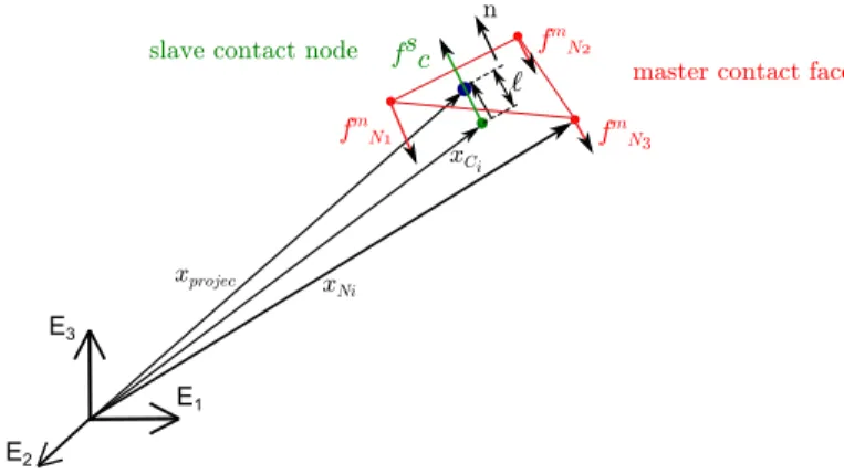
The contact force (Eqn. 19) applied on each contact node of the slave or the master body has its magnitude f defined by the
E1 E3
E2
xCi
master contact face slave contact node
n xprojec xNi fsc fm N1 fm N2 fm N3 `
FIGURE 4. KINEMATICS OF CONTACT FORCE.
contact law (Eqn. 16) and its direction given by the normal vector nof the master contact surface involved in the slave-master pair considered. For the master body, the participation factors w per-mit to distribute the contact force on the master nodes deliper-miting the master surface (see Fig. 4). In case of triangular contact faces, these participation factors are equivalent to the barycentric coor-dinates already computed in the detection algorithm presented in the previous Section. For the slave body, the parameter w is ob-viously always equal to one because the contact force amplitude is computed at this node.
fc= w f n (19)
The contact nodes can be interpreted as virtual nodes since they do not necessarily correspond to the superelement boundary nodes. Therefore, each contact force applied on these virtual nodes has to be transfered to the generalized coordinates vector qof the superelement, loading thus the boundary nodes and the modal variables.
Since the contact force model is based on a penalty method, no kinematic constraint is involved and the contribution of this force element to the motion equations (Eqn. 1) of the multibody sysem is only contained in the term of internal forces, gint(q, ˙q).
The virtual work principle is used in order to find the internal force vector inherent in each nodal contact force:
δWCcon i =δx
T
Ci fc (20)
The virtual displacements δxCi of the contact points are easily obtained by deriving Equation (3):
δxCi =δx0− R0(X^Ci+ uCi)δΘ0+ R0δuCi (21) =δx0− R0 ^ ( XCi+ΨCiη ) δΘ0+ R0ΨCiPδq (22)
whereΨCi are the 3 rows of the mode matrixΨ linked to the i
th
contact node,δΘ0is the vector of virtual rotation in the
corota-tional frame such that gδΘ0= RT0 δR0(see Ref. [11]).
The internal force vector gconC
i (Eqn. 24) corresponding to the contact force fc can now be easily obtained by
identifica-tion with the classical virtual work expression for a force element (Eqn. 23): δW =δqT gint (23) gCint,con i = P TΨT CiR T 0 fc+ fc ^ ( XCi+ΨCiη ) RT 0 fc 0 0 0 (24)
The tangent stiffness and damping matrices have been computed analytically but are not given in this paper for the sake of con-ciseness.
NUMERICAL RESULTS
The results presented in this Section demonstrate the rele-vance the contact method proposed for the dynamic analysis of two different systems representative of transmission devices.
For both models the 3D geometry of each body is con-structed in a CAD software (CATIA V5). The mesh to obtain the initial finite element model as well as the computation of the reduced matrices (M, K,Ψ) of the superelement are achieved us-ing the SAMCEF FE software [12]. Dynamic analysis with the proposed contact formulation is fully implemented in MATLAB and the integration of the DAE-system (Eqn. 1-2) during the full model simulation is also performed in this development code.
Simple contact example
In order to assess the contact formulation developed in this work, the simulation of a benchmark problem has been per-formed. The system modeled is composed of two bars con-strained at their center of mass by a hinge joint along the x-axis and the contact is induced by a torque applied along the rotation axis of the bar #1 (see Fig. 5). This system can be seen as a very simplified driving cam mechanism.
The bars are meshed with hexahedral finite elements and the material used is basic steel (Young modulus: 210 GPa, Pois-son ratio: 0.3 , mass density: 7800 kg/m3). For each bar, the 8 vertices have been chosen as boundary nodes and 10 vibration modes are taken into account. The eigen frequencies of the first 10 vibration modes are in the range [603; 3210] Hz for bar #1
1 m 0.1 m 0.1 m 0.8 m 0.2 m 0.15 m x y z # 1 slave body # 2 master body driving torque resisting torque
(a) INITIAL CONFIGURATION (t = 0 s)
(b) FINAL CONFIGURATION (t = 0.15 s)
FIGURE 5. BENCHMARK: POSITIONS OF THE BARS.
and in the range [391; 3008] Hz for bar #2. These choices are arbitrary for this simple model. Such a small number of inter-nal modes included in the superelement enables to verify that the contact element can work with only a few global shape func-tions in the reduction basis (Ψ). The results provided are accept-able even though the accuracy of system response would improve with a higher number of modes.
In the initial configuration, the bars are separated by a gap to evaluate the ability of the contact element to deal with uni-lateral contact with impact. A torque is applied on the additional node linked to the corotational frame of bar #1 whereas a viscous torque acts against the rotation of bar #2. The simulation is per-formed with a time step of 1.E-5 s in order to be able to capture all the vibration modes of both superelements.
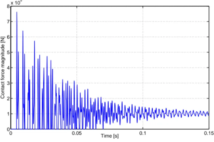
Figure 6 displays the magnitude of the total contact force between the two bars versus time. Due to the initial gap, several rebonds can be observed during the first part of the simulation before occurrence of a close contact situation. The excitation of superelement internal modes as well as the contact law based on a spring-damping system can explain the oscillations on the contact force curve. For both bodies, the candidate contact zone assessed by the contact detection algorithm is depicted in gray
0 0.05 0.1 0.15 0 1 2 3 4 5 6 7 8x 10 5 Time [s]
Contact force magnitude [N]
FIGURE 6. MAGNITUDE OF THE TOTAL CONTACT FORCE
BETWEEN THE TWO BARS.
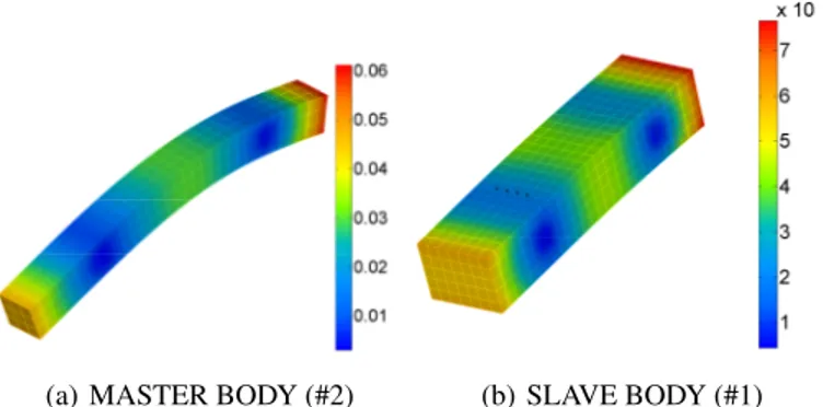
in Figure 7 and the effective contact area is colored in red for a particular time step (t = 0.1 s). The bar deflections at the same time step are represented in Figure 8.
(a) MASTER BODY (#2) (b) SLAVE BODY (#1)
FIGURE 7. CANDIDATE CONTACT ZONES DEPICTED IN
GRAY AND EFFECTIVE CONTACT ZONE COLORED IN RED (t = 0.1 s).
Gear pair model
Multibody dynamics analysis of gear pairs is often based on the expression of macroscopic kinematic constraints defined between two rigid bodies representing both gear wheels. These global models may use a spring and damper combination along the normal pressure line in order to represent the virtual contact points between teeth (see Reference [13]). Such formulation of gear pair models is compact and enables to simulate complex mechanisms including gears with relatively low computational time. However, only properly meshing gears can be considered
(a) MASTER BODY (#2) (b) SLAVE BODY (#1)
FIGURE 8. BAR DEFLECTIONS AT t = 0.1 s (DEFORMED
AM-PLIFICATION FACTOR: 100). #1, pinion slave body #2, gear master body candidate contact zones prescribed rotation viscous torque boundary nodes
FIGURE 9. GEAR MESHING MODELED WITH CONTACT
CON-DITIONS BETWEEN SUPERELEMENTS.
since the disruptive effects are most of the time quite approxi-mately represented. For instance, transmission devices with mis-alignment or crossed axes can hardly be represented.
To model more accurately the gear flexibility and cap-ture meshing defaults, expressing the contact conditions be-tween detailed finite element models of the gear wheels is often needed, [5]. Such detailed models are without doubt the most re-liable technique but they are quite complex to develop and they involve a high computational time.
The modeling of gear wheels as superelements combined with the contact condition described previously allows to account for the tooth flexibility and model the misalignment, the gear hammering and the backlash with higher accuracy than classical global models. Moreover, the formulation is more compact than with standard FE models. The proposed model takes into account the actual 3D geometry of the gear wheels (Fig. 9) and therefore can predict the actual contact points on teeth flanks.
All tooth flanks are candidate contact zones, therefore a con-tact detection loop over all flanks of both gear wheels would be numerically extremely costly. To avoid this huge number of pro-jections, a reference node can be associated to each tooth flank. At each iteration, the absolute position of these reference nodes is computed and the closest flank to the center distance of the gear pair is determined for both wheels. The collision detection method is performed for these two candidate contact zones as well as for a small number of flanks on either side of the central flank. Usually, the number of tooth pairs simultaneously in con-tact does not exceed three, so that the potential concon-tact zones are often limited to six.
When developing the model, the number and the location of boundary nodes have to chosen with great care. Indeed, the sys-tem response is significantly influenced by the static modes. Fur-thermore, the shape functions of vibration modes depend directly on the spatial distribution of boundary nodes in the superelement. In order to describe properly the bending mode of each tooth, at least one boundary node per tooth has to be retained.
In a first phase, for each tooth the closest node to the cen-ter of the tooth tip face was selected as boundary node. How-ever, simulation results have shown a large localized deformation around each boundary node. These non-uniform strains on tooth flanks lead to partial contact paths along the wheel facewidth.
A solution to avoid this drawback consists in adding an ad-ditional independent node at each tooth flank center and link this node to the flank nodes by kinematic constraints. These extra nodes are retained as boundary nodes of the gear wheel.
The value of the 6 DOF related to the additional node intro-duced by these 6 constraints can be interpreted as the mean po-sition and rotation of the node group located on the tooth flank. The aim of this mean element (see Ref. [12]) is similar to the corotational frame definition presented in this paper (Eqn. 13) but the kinematic constraints are not at the same level of the model-ing approach. Indeed, the constraints allowmodel-ing to determine the position and the orientation of the additional node are defined between nodes of the initial finite element model, whereas the corotational frame constraints are based on the boundary nodes of the reduced model.
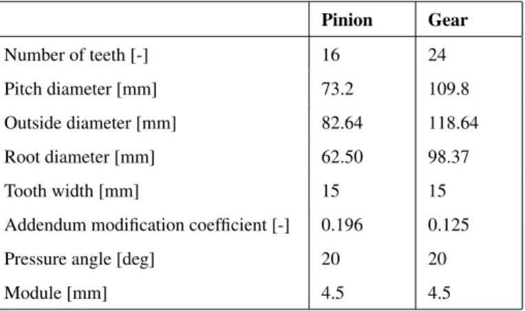
The geometric data of the pinion and the gear are summa-rized in Table 1 and the material properties are the same as the bars in the benchmark system presented previously. The su-perelement of each gear wheel is composed of two boundary nodes, one per tooth flank, and 100 vibration modes. The eigen frequencies are in the range [19520; 146068] Hz for the pinion and in the range [10402; 115469] Hz for the gear.
A hinge joint between the ground and the node representing the corotational frame (x0,α0) is used to avoid the inclination of
the wheel rotation axis. In order to analyze the dynamic response when there is a backlash between teeth, the center distance is set to 91, 5 mm. At the initial time, the two gear are not in con-tact and their rotation velocities are prescribed (−1000 rpm for
TABLE 1. GEOMETRIC DATA OF SPUR GEAR WHEELS [14]. Pinion Gear Number of teeth [-] 16 24 Pitch diameter [mm] 73.2 109.8 Outside diameter [mm] 82.64 118.64 Root diameter [mm] 62.50 98.37 Tooth width [mm] 15 15
Addendum modification coefficient [-] 0.196 0.125 Pressure angle [deg] 20 20
Module [mm] 4.5 4.5
the pinion and 667 rpm for the gear according to the transmis-sion ratio). During the whole simulation, the gear rotation is still prescribed at the same velocity whereas a viscous torque
(T =−1·ω(rad/s)) is applied on the pinion. This torque tends
to slow down the gear and lead to contact between teeth of the geared wheels. The penalty factor kpof the contact law has been
chosen higher than tooth stiffness to have a penetration length between the two bodies much smaller that the tooth deformation. The damping coefficient c has been set to a value allowing to introduce enough dissipation to manage the impact phenomena due to backlash. The simulation is performed with a fixed time step of 1.E-6 s.
Figure 10 displays the magnitude of the contact force ap-plied on tooth flanks. For the first contacts, the time periods without any contact between wheels are due to backlash. When there is contact, one or two pairs of teeth can be in contact at the same time according to the relative position of the gear wheels.
The oscillations observed on contact curves can be explained by the mode excitations of both superelements. The time evolu-tion of modal variables of the gear #1 are depicted in Fig. 11 and the displacements of boundary nodes are represented in Fig-ure 12. The static and internal modes are mainly excited during the transient periods when the active contact zone switches from one tooth pair to another. The boundary node related to a tooth flank in contact undergoes a deformation and the boundary node linked to the other flank of the same tooth is also submitted to a displacement but with a lower amplitude. The boundary nodes related to the teeth not in contact are submitted to much smaller displacements due to the corotational frame constraint.
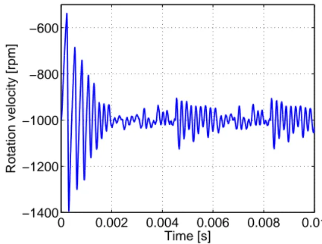
The deformations in gear wheels when there is contact be-tween teeth are mainly localized on teeth (see Fig. 13). The rota-tion velocity of the pinion versus time is illustrated in Figure 14 where the decreasing of oscillations is due to the viscous torque applied on this wheel and the damping force introduced in the contact law. 0 0.002 0.004 0.006 0.008 0.01 0 2000 4000 6000 8000 10000 12000 Time [s]
Contact force magnitude [N]
tooth 8 / flank 2 tooth 9 / flank 2 tooth 10 / flank 2 tooth 11 / flank 2
FIGURE 10. CONTACT FORCE ON TOOTH FLANKS (GEAR #1).
0 0.002 0.004 0.006 0.008 0.01 −5 −4 −3 −2 −1 0 1 2x 10 −7 Time [s] Modal amplitudes [−]
FIGURE 11. TIME EVOLUTION OF MODAL VARIABLES
(GEAR #1)
CONCLUSION
This paper proposes a contact model between elastic bodies based on the use of superelements. The flexibility of the bodies subjected to contact conditions is represented by a reduced or-der model defined in a corotational frame, so that linear elastic behavior can be assumed in case of small strains. The reduction basis allowing to construct the reduced matrices of each superele-ment is composed of a mixed set of static and vibration modes in accordance with the Craig-Bampton method.
In order to keep the model compact, the contact formulation developed does not require that the candidate contact nodes are included in the set of boundary nodes. Therefore, a large number of nodes of the skin can be condensed. At each simulation time, the absolute position of the candidate contact nodes is computed
0 0.002 0.004 0.006 0.008 0.01 0 0.5 1 1.5 2 2.5 3x 10 −5 Time [s]
Displacement of boundary nodes [m]
tooth 8 / flank 2 tooth 8 / flank 1 tooth 9 / flank 2 tooth 9 / flank 1 tooth 10 / flank 2 tooth 10 / flank 1 tooth 11 / flank 2 tooth 11 / flank 1 other boundary nodes
FIGURE 12. BOUNDARY NODE DISPLACEMENTS (GEAR #1).
FIGURE 13. DEFORMATION OF GEAR WHEELS DUE TO
CON-TACT BETWEEN TEETH (t =8.8E-4 s).
in terms of the corotational frame position and rotation matrix together with the vector of superelement local coordinates ex-pressed in the corotational frame. To detect the effective contact zones, a node-to-surface projection method is used.
A contact law based on a penalty method enables to deter-mine the magnitude of each contact force between a slave node and a master face element. Finally, each individual contact force is transfered to the generalized coordinate vector, loading thus the boundary nodes and the modal coordinates.
The contact formulation developed can be seen as a com-promise between the different contact models classically used in dynamic simulations of systems. On one hand, the contact de-fined between rigid bodies are often compact and computation-ally efficient even for large and complex mechanical systems but can lead to unreliable responses if the flexibility effects are
sig-0 0.002 0.004 0.006 0.008 0.01 −1400 −1200 −1000 −800 −600 Time [s] Rotation velocity [rpm]
FIGURE 14. ROTATION VELOCITY OF THE PINION.
nificant. On the other hand, contact conditions based on finite element models of flexible bodies enable to study the deforma-tion and vibradeforma-tion phenomena. Unfortunately, these models are often computationally inefficient for industrial applications.
The contact element has been assessed by the simulation of a first crude example composed of two bars in rotation. A spur gear pair model submitted to backlash has also been studied. Fu-ture work will address the improvement of the formulation to account for the friction forces produced by contacts and the lin-ear viscoelastic contact law will be replaced by a nonlinlin-ear law based on the Hertz’s theory. The modeling of other kinds of gear pairs such as helical gears submitted to misalignment will be also investigated.
ACKNOWLEDGMENT
The first author, Geoffrey Virlez, would like to acknowledge the Belgian National Fund for Scientific research (FRIA) for its financial support. The last author, M. G´eradin, acknowledges the support of LMS-Samtech (Li`ege, Belgium) for its contribution to this research.
REFERENCES
[1] Flores, P., Ambr´osio, J., Claro, J. C. P., and Lankarani, H. M., 2006. “Influence of the contact-impact force model on the dynamic response of multi-body systems”. Proc. IMechE Vol. 220 Part K: J. Multi-body Dynamics.
[2] Pfeiffer, F., 2008. “On non-smooth dynamics.”. Meccanica, 43, pp. 533–554.
[3] Ziegler, P., and Eberhard, P., 2011. “Investigation of gears using an elastic multibody model with contact”. Multi-body Dynamics: Computational Methods and Applications,
Computational Methods in Applied Sciences, 23, pp. 309– 327.
[4] Cavalieri, F., and Cardona, A., 2012. “An augmented La-grangian technique combined with a mortar algorithm for modelling mechanical contact problems”. International Journal for Numerical Methods in Engineering, 93(4), pp. 420–442.
[5] Lin, T., Ou, H., and Li, R., 2007. “A finite element method for 3d static and dynamic contact/impact analysis of gear drives”. Computer Methods in Applied Mechanics and En-gineering, 196, pp. 1716–1728.
[6] G´eradin, M., and Rixen, D., 2001. Mechanical Vibrations -Theory and Apllication to Structural Dynamics, 2 ed. John Wiley & Sons, New York.
[7] Cardona, A., 2000. “Superelements modelling in flexible multibody dynamics”. Multibody System Dynamics, 4, pp. 245–266.
[8] Chung, J., and Hulbert, G., 1993. “A time integration al-gorithm for structural dynamics with improved numerical dissipation: The generalized-αmethod”. ASME Journal of Applied Mechanics, 60, pp. 371–375.
[9] Arnold, M., and Br¨uls, O., 2007. “Convergence of the generalized-α scheme for constrained mechanical sys-tems”. Multibody System Dynamics, 18(2), pp. 185–202. [10] Shabana, A. A., and Wehage, R., 1983. “A coordinate
re-duction technique for dynamic analysis of spatial substruc-tures with angular rotations”. Journal of Structural Me-chanics, 11, pp. 401–431.
[11] G´eradin, M., and Cardona, A., 2001. Flexible multibody dynamics: A finite element approach. John Wiley & Sons, New York.
[12] LMS-SAMTECH S.A. SAMCEF/DYNAM V13 - User’s and Installation Manuel.
[13] Cardona, A., 1995. “Flexible three dimensional gear mod-elling”. European journal of computational mechanics, 268(5-6), pp. 663–691.
[14] Lundvall, O., Str¨omberg, N., and Klarbring, A., 2004. “A flexible multi-body approach for frictional contact in spur gears”. Journal of Sound and Vibration, 278, pp. 479–499.