Development of ceramic reinforced iron aluminide
based composite coatings for wear resistant
applications
Thèse
Mahdi Amiriyan
Doctorat en génie des matériaux et de la métallurgie
Philosophiæ doctor (Ph. D.)
DEVELOPEMENT OF CERAMIC REINFORCED IRON
ALUMINIDE BASED COMPOSITE COATINGS FOR WEAR
RESISTANT APPLICATIONS
Thèse
Mahdi Amiriyan
Sous la direction de :
Houshang D. Alamdari, directeur de recherche
Carl Blais, codirecteur de recherche
Résumé
Les composés intermétalliques Fe3Al et leurs revêtements composites sont des matériaux structuraux potentiels
pour des applications tribologiques. Parmi les composites, ceux obtenus par broyage mécanique à haute énergie possèdent plusieurs avantages, en particulier une fabrication rentable. Le broyage à billes à haute énergie permet également une large gamme de fraction volumique des particules de renforcement. Dans cette recherche, Nous avons préparé des revêtements composites à matrice d'aluminiure de fer, basés sur la composition chimique de Fe3Al avec des particules de renforcement de TiC et de TiB2 en utilisant un broyeur à billes à haute énergie et
déposé par la technique HVOF (High Velocity Oxy Fuel). L'effet des paramètres de traitement tels que la durée du broyage et le traitement thermique subséquent sur les la matière première destinés à la projection par HVOF a été étudié. Les paramètres de traitement ont joué des rôles importants sur la poudre composite et par la suite sur la microstructure, les propriétés mécaniques et tribologiques des revêtements.
Le but de la première phase expérimentale de ce travail était d'étudier l'effet des particules de TiC in situ sur la microstructure, le comportement mécanique et tribologique des revêtements de Fe3Al déposés par HVOF. Dans
cette étape, des poudres composites Fe3Al / TiC avec différentes quantités de carbure de titane ont été produites par
broyage à haute énergie. Un mélange de Fe3Al-Ti-C a été broyé pendant 6 h suivi d'un traitement thermique à 1000
°C pendant 2 h sous vide poussé. Des revêtements composites d'aluminure de fer renforcés au TiC in situ ont été préparés pour améliorer la dureté Vickers et la résistance à l'usure des intermétalliques de Fe3Al. Les revêtements
composites consistent principalement en une phase de TiC uniformément dispersée dans des lamelles de la matrice de Fe3Al. Les revêtements composites ont montré une dureté Vickers croissante avec l’augmentation de la quantité
de TiC, allant jusqu'à 70 % en moles de TiC. La résistance à l'usure par glissement à sec des revêtements a été augmentée avec l'addition de particules de TiC formées in situ. Les revêtements composites de Fe3Al déposés par
HVOF avec des renforts en TiC de 50 % et 70 % en moles présentaient une excellente résistance à l'usure par glissement. Le mécanisme d'usure dominant de ces revêtements était l'abrasion et l'oxydation.
Dans une autre étape de ce travail, des poudres composites de Fe3Al-TiB2 avec deux quantités différentes de borure
ont été produites par le dépôt par high Velocity Oxy Fuel (HVOF) sur un substrat en acier. Les revêtements composites consistaient principalement en une phase de TiB2 pré-synthétisée et uniformément dispersée dans des
lamelles de la matrice de Fe3Al. Il a été montré qu'en augmentant la fraction volumique du TiB2, la dureté Vickers et
la résistance à l'usure par glissement des revêtements contre le contre-corps en alumine (6,33 mm de diamètre) étaient augmentées. L'augmentation de la résistance à l'usure était censée être liée à l'amélioration de la dureté, qui à son tour est due à la présence de particules de TiB2 dans la matrice Fe3Al. Le taux d'usure de glissement des
revêtements a augmenté pour atteindre un maximum lorsque la vitesse de glissement augmente, puis il a diminué avec l'augmentation supplémentaire de la vitesse de glissement. Les analyses chimiques des surfaces usées ont montré que des vitesses de glissement plus élevées entraînent une oxydation plus élevée de la surface, probablement en raison de la température locale plus élevée. Une telle couche d'oxyde semble agir comme une barrière entre deux corps coulissants, diminuant ainsi le taux d'usure.
Abstract
Fe3Al intermetallic compounds and their composite coatings are potential structural materials for tribological
applications. High-energy ball milled powders possess several advantages, especially cost-effective fabrication and lower cost of reinforcement. High-energy ball mill also allows for a wide range of reinforcement volume fraction. In this research, Iron Aluminide matrix composite coatings based on Fe3Al chemical composition with TiC and TiB2
particles were prepared using a high-energy ball mill and deposited via the High Velocity Oxy Fuel (HVOF) technique. The effect of processing parameters such as ball milling duration and subsequent heat treatment soaking time and temperature on the phases of products as a feed stock for the HVOF gun was studied. The processing parameters played important roles on the microstructure, mechanical and tribological properties of the coatings. The aim of the first experimental stage of this work was to study the effect of in-situ TiC particles on microstructure, mechanical and tribological behavior of HVOF deposited Fe3Al coatings. In this stage Fe3Al/TiC composite powders
with different carbide quantities were produced via high-energy ball milling of Fe3Al-Ti-C system for 6 h followed by
heat treatment at 1000 °C for 2 h under high vacuum. In-situ TiC-reinforced iron aluminide composite coatings were prepared to improve the Vickers hardness and wear resistance of Fe3Al intermetallics. The composite coatings
mainly consist of a TiC phase uniformly dispersed within lamellae of the Fe3Al matrix. The composite coatings
showed increasing Vickers hardness with increasing TiC content up to 70 mol% TiC. The dry sliding wear resistance of coatings was increased with the addition of in-situ formed TiC particles. HVOF deposited Fe3Al composite coatings
with 50 and 70 mol% TiC reinforcements exhibited excellent sliding wear resistance. The dominant wear mechanism in those coatings was abrasion and oxidation.
In another stage of this work Fe3Al-TiB2 composite powders with two different boride quantities were produced by the
high Velocity Oxy Fuel (HVOF) spray deposition on a steel substrate. The composite coatings mainly consisted of a TiB2 phase uniformly dispersed within lamellae of the Fe3Al matrix. It was shown that by increasing the volume
fraction of TiB2 both the Vickers hardness and sliding wear resistance of the coatings against alumina counterbody
(6.33 mm in diameter) were increased. The increase of wear resistance was believed to be related to the hardness enhancement, which, in turn, is due to the presence of TiB2 particles within the Fe3Al matrix. The sliding wear rate of
the coatings increased to reach a maximum as the sliding speed increases, and then it decreased with further increase of the sliding speed. The chemical analyses of the worn surfaces showed that higher sliding speeds result in higher oxidation of the surface, most likely due to the higher local temperature. Such an oxide layer seems to act as a barrier between two sliding bodies, thus decreasing the wear rate.
Table of Contents
Résumé... iii
Abstract ... iv
Table of Contents ... v
List of Tables... viii
List of Figures ... ix
Acknowledgments ... xii
Preface ... xiii
Introduction ... 1
Coatings; From Ancient Time to Now... 1
Iron Aluminides as Coatings ... 1
Thermal Spray Coatings and Present Work ... 2
Problem Statement ... 3
Hypothesis ... 3
Objectives ... 4
Chapter 1: Literature Review ... 5
1.1 Surface Engineering and Coatings ... 5
1.2 Metallic and Intermetallic Coatings ... 6
1.3 Aluminides ... 7
1.3.1 Iron-Aluminides ... 8
1.4 Physical and Mechanical Properties of Fe-Al System ... 9
1.4.1 Fe-Al Phase Diagram and Atomic Structure ... 9
1.4.2 Mechanical Properties of Iron Aluminides and its Composites ... 11
1.5 Tribology of Iron Aluminide Coatings ... 19
1.5.1 Friction ... 19 1.5.2 Wear Behavior ... 22 1.5.3 Abrasion Wear ... 24 1.5.4 Erosion Wear ... 25 1.5.5 Fatigue Wear ... 25 1.5.6 Chemical Wear ... 25
1.6 Iron Aluminide-Based Composites and Composite Coatings ... 26
1.6.2 Toughening of Iron Aluminide Based Coatings and Composites ... 30
1.6.3 Fe-Al/TiC Composites ... 32
1.6.4 Fe-Al/TiB2 Composites ... 35
Chapter 2: Dry Sliding Wear Behavior of unreinforced Fe3Al and in-situ Fe3Al/TiC Composite Coatings ... 38
Résumé ... 38
Abstract ... 38
2.1 Introduction ... 39
2.2 Materials and Methods ... 40
2.2.1 Sample Preparation ... 40
2.2.2 Friction and Wear Testing ... 41
2.2.3 Characterization... 41
2.3 Results and Discussion ... 41
2.3.1 Feedstock Powder and Coating Characterization ... 41
2.3.2 Wear Rates ... 48
2.4 Summary ... 53
Chapter 3: Tribo-Mechanical Properties of HVOF Deposited Fe3Al Coatings Reinforced with TiB2 Particles for Wear-Resistant Applications... 55
Résumé ... 55
Abstract ... 55
3.1 Introduction ... 56
3.2 Materials and Methods ... 57
3.3 Results and Discussion ... 58
3.4 Summary ... 73
Chapter 4: Mechanical Behavior and Sliding Wear Studies on Iron Aluminide Coatings Reinforced with Titanium Carbide ... 75
Résumé ... 75
Abstract ... 75
4.1 Introduction ... 76
4.2 Materials and Methods ... 76
4.3 Results and Discussion ... 79
4.4 Summary ... 88
General Discussion and Conclusion ... 90
Effect of high-energy ball milling ... 91
Effect of in-situ ceramic incorporation ... 92
Effects of ex-situ ceramic incorporation ... 93
Effects of sliding speed and load ... 94
Simultaneous incorporation of in-situ and ex-situ ceramics ... 94
Future work ... 96
References ... 98
List of Tables
Table 1-1. An overall comparison of various surface engineering processes (adapted from [4]) ... 6
Table 1-2. Properties of some interesting aluminides (after [15, 17, 24-26]) ... 8
Table 1-3. Mechanical properties of Fe-Al-Cr alloys tested at room temperature (with some changes from [30]) ... 9
Table 1-4. Hardness of FeAl composites with 50 vol.% ceramic addition (adapted from Schneibel et al. [121]) ... 33
Table 1-5. Mechanical properties of Fe–28Al–5Cr/TiC composites (adapted from Zhang et al. [123])... 34
Table 2-1. Nominal composition of the samples ... 40
Table 2-2. HVOF spraying parameters ... 40
Table 3-1. HVOF spraying parameters ... 57
Table 3-2. Microindentation hardness, reduced elastic modulus and H/E ratio of the coatings ... 63
Table 4-1. High-Velocity Oxy-Fuel (HVOF) spraying parameters ... 77
List of Figures
Figure 1-1. Tribologically important properties in different zones of the coated surface [1] ... 5
Figure 1-2. The change of coefficient of friction with soft metallic coatings, lubricated ball-on-disk test condition [12] . 7 Figure 1-3. Fe-Al phase diagram (Adapted from Chen & Kovacevic [42]) ... 10
Figure 1-4 Lattice site for (a) FeAl and (b) Fe3Al; Key: black and red circles represent Fe and Al atoms, respectively (Adapted from Frommeyer et al. [43]) ... 11
Figure 1-5 The effect of atmosphere on stress-strain behavior of Fe-25 at.% Al (Adapted from Stoloff & Duquette [29]) ... 12
Figure 1-6 Schematic illustration of the effect of particle size on the wear of a metallic matrix: (top) when the mean particle size is of the order of the surface roughness, particles are not effective restricting the damage of the matrix; (bottom) coarse particles (mean particle size is six times larger than that of (top)) provide better protection to the matrix and may induce damage to the counterface (Adapted from Alpas & Zhang [56]) ... 14
Figure 1-7. Typical microstructures of Fe3Al coatings sprayed at different spraying speeds; (a) 390 m/s, (b) 560 m/s, and (c) 620 m/s (after [66]) ... 17
Figure 1-8. The effect of Al content on the Young’s modulus at different temperatures [24] ... 18
Figure 1-9. The three components of sliding friction are (a) adhesion, (b) ploughing and (c) asperity deformation (Adapted from Suh & Sin [76] and Holmberg & Matthews [1]) ... 21
Figure 1-10. Variation of friction coefficient as a function of sliding distance for a Fe-30Al alloy having B2 structure (Adapted from Kim & Kim [79])... 21
Figure 1-11. Effect of load on the friction coefficient vs. sliding distance: (a) Fe–Al coating and (b) Fe–Al/WC coating (v = 0.8 m×s−1) [58] ... 22
Figure 1-12. The basic mechanisms of wear are (a) adhesive, (b) abrasive, (c) fatigue and (d) chemical wear (Adapted from Holmberg & Matthews [1]) ... 23
Figure 1-13. Wear rate of Fe-Al coating and Fe-Al/WC composite coating under different load (Adapted from Xu et al. [58]) ... 24
Figure 1-14. Possible stages Al deposition by CVD-FBR process on ferritic steel (after Perez et al. [97]) ... 27
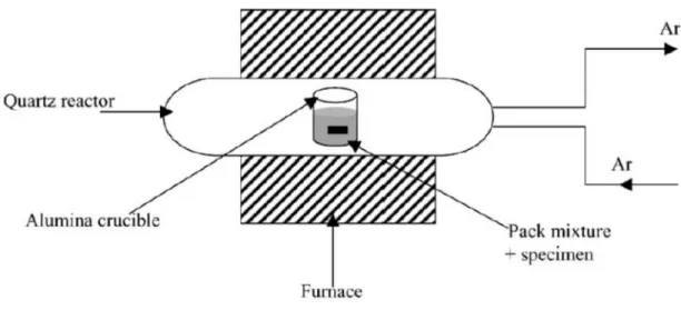
Figure 1-15. Schematic diagram of the pack aluminisation device (after Houngninou et al. [102]) ... 28
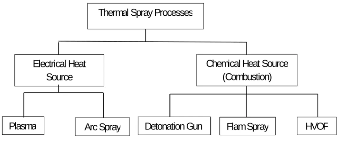
Figure 1-16. Different thermal spray techniques used in both industry and research ... 29
Figure 1-17. Schematic of an HVOF gun (after Li & Christofides [111]) ... 30
Figure 1-18. Hardness of the FeAl/ceramic composites, and WC/Co as a function of ceramic volume fraction (after Schneibel et al. [121]) ... 33
Figure 1-19. TEM investigations of the 15-h milled Fe-Al-Ti-C system (adapted from Krasnowski et al. [125]) ... 35
Figure 1-20. FeAl–40 vol.% TiB2 cemented carbide: (a) as polished microstructure (light phase = FeAl binder, dark phase = TiB2 particles); (b) damage inside the erosion crater (25 °C) [128]... 36
Figure 1-21. Fracture mode of Fe3Al-based alloys produced in tension at room temperature: (a) transgranular cleavage in Fe-28% Al, (b) mostly intergranular failure in Fe-28% Al with TiB2, and (c) mixed transgranular cleavage and intergranular failure in Fe-28% Al-4% Cr [16] ... 37
Figure 2-1. XRD profiles of Fe3Al-Ti-C powders mechanically alloyed for (0-12) h ... 42
Figure 2-2. XRD profiles of powders mechanically alloyed for 6 h ... 42
Figure 2-3. XRD patterns of the Fe3Al–TiC composite powders milled for 6h and heat treated at 1000 °C for 2 h ... 43
Figure 2-4. SEM images showing morphology at (a) X100 and (aʹ) X1000; (b) particle size distribution of the Fe3Al– 50 mol%TiC composite powder after sieving ... 44 Figure 2-5. Cross sectional back-scattered SEM images of Fe3Al–50 mol%TiC powder (mounted in epoxy resin) at:
Figure 2-6. Cross sectional back-scattered SEM images of the (a) Fe3Al, (b) 10, (c) 30, (d) 50, and (e) 70 mol%TiC
coatings... 46 Figure 2-7. EDS spectra of the (a) main gray phase in Fe3Al coating, (b) main gray phase in Fe3Al–TiC coating, (c)
dark gray oxide inclusions and (d) light gray Al-depleted areas... 47 Figure 2-8. Hardness of the coatings as a function of different TiC content ... 47 Figure 2-9. Wear rate of the coatings at different sliding speeds; (Top) Pure Fe3Al, 10 and 30 mol% TiC samples and
(Bottom) 50 and 70 mol %TiC samples ... 49 Figure 2-10. SEM morphologies at different magnifications of the worn surfaces for pure Fe3Al at a sliding speed of
(a, aʹ and a″) 0.04 m×s-1 and (b, bʹ and b″) 0.1 m×s-1. (c) Shows a microcrack in cross-sectional view of the sample
worn at 0.1 m×s-1 ... 50
Figure 2-11. EDS spectra of the worn surface of Fe3Al coating at (a) 0.04 m×s-1 and (b) 0.8 m×s-1 ... 51
Figure 2-12. SEM morphologies at different magnifications of the alumina counterpart used against pure Fe3Al at a
sliding speed of (a and aʹ) 0.04 and (b and bʹ) 0.8 m×s-1 under a load of 5 N ... 52
Figure 3-1. XRD patterns of the (a) Fe3Al-30 vol.% TiB2 and (b) Fe3Al-50 vol.% TiB2 HVOF composite coatings... 59
Figure 3-2. Cross-sectional backscattered SEM images of the unreinforced (0 vol.% TiB2) Fe3Al (a and a’), 30 (b and
b’) and 50 (c and c’) vol.% TiB2 coatings. The arrow on a’ indicates a pore. ... 60
Figure 3-3. EDS spectra of the (a) main grey phase in Fe3Al coating, (b) dark grey oxide inclusions, (c) light grey
areas and (d) TiB2 particles ... 61
Figure 3-4. Hardness of the substrate and coatings as a function of different TiB2 content ... 62
Figure 3-5. Typical load-displacement curves of the coatings ... 62 Figure 3-6. SEM images of Vickers indentation cracks (induced at high load of 1000 g) on (a) Fe3Al, (b) Fe3Al-30
vol.% TiB2 and (c) Fe3Al-50 vol.% TiB2 coating cross sections. Crack propagation paths have been indicated by white
ovals. ... 63 Figure 3-7. Typical friction coefficient curve for a thermally sprayed Fe3Al coating... 64
Figure 3-8. Friction coefficient versus sliding speed at the applied load of 5 N ... 65 Figure 3-9. Wear rates as a function of sliding speed and applied load. (a) Fe3Al coatings and (b–d) composite
coatings... 66 Figure 3-10. SEM images at different magnifications of the worn surfaces for Fe3Al at a sliding speed of (a and a’)
0.04, (b and b’) 0.1 and (c and c’) 0.8 m×s−1 under a load of 5 N. EDS was taken from the points marked by X. ... 68
Figure 3-11. EDS spectra of the worn surface of Fe3Al coating at (a) 0.04 and (b) 0.8 m×s−1 ... 69
Figure 3-12. SEM images at different magnifications of the alumina counterpart used against Fe3Al at a sliding speed
of (a and a’) 0.04, (b and b’) 0.1, (c and c’) 0.3 and (d and d’) 0.8 m×s−1; (a”) EDS spectrum of the transferred layer
obtained at the highest speed under a load of 5 N. EDS was taken from the points marked by X. ... 70 Figure 3-13. SEM images at different magnifications of the worn surfaces for Fe3Al-50 vol.% TiB2 at a sliding speed
of (a and a’) 0.04, (b and b’) 0.1, (c and c’) 0.3 and (d and d’) 0.8 m×s−1 under a load of 5 N ... 71
Figure 3-14. Microscopic morphologies of the wear debris of the Fe3Al-TiB2 composite coatings worn at sliding speed
of (a) 0.04 and (b) 0.3 m×s−1 ... 72
Figure 3-15. SEM images at different magnifications of the alumina counterpart used against Fe3Al-50 vol.% TiB2 at a
sliding speed of (a and a’) 0.04, (b and b’) 0.3 and (c and c’) 0.8 m×s−1 under 5 N load ... 73
Figure 4-1. Optical microscopic image of a misplaced microindentation trace on a pore ... 78 Figure 4-2. Schematic illustration of ball-on-disk tribotester ... 79 Figure 4-3. Scanning Electron Microscopic (SEM) images of the (a,b) milled 30 and 50 vol.% composite powders and (c) particle size distribution of the feedstock ... 80
Figure 4-4. X-ray diffractometer (XRD) patterns of the commercial starting powders and as-sprayed Fe3Al–TiC
coatings... 81 Figure 4-5. (a) SEM back-scattered image and (b,c) mapping of titanium and carbon respectively ... 82 Figure 4-6. Microindentation images and load-displacement curves of (a) unreinforced Fe3Al, (b) Fe3Al–30 vol.% TiC
and (c) Fe3Al–30 vol.% TiC ... 83
Figure 4-7. Schematic representation of indenter-sample contact cross section (a) and a graphical view of load-displacement data (b) ... 84 Figure 4-8. Fracture surface SEM images of thermally sprayed coatings: (a) a general profile, (b) unreinforced Fe3Al
and (c) Fe3Al–50 vol.% TiC sample. Arrows in b show large decohesion at splat interfaces. Arrows in c show well
bonded TiC particles in the Fe3Al matrix. ... 87
Figure 4-9. Fracture surface SEM image of a Fe3Al–TiC coating showing TiC particles embedded in the matrix ... 87
Figure 4-10. SEM images of the sliding wear tracks of (a,b) unreinforced Fe3Al and (c,d) Fe3Al–50 vol.% TiC
Acknowledgments
I would like to take the opportunity and express my sincere appreciation to a number of people who have been great pillars of support throughout the course of this research.
First and foremost, I would like to thank my supervisor Prof. Houshang D. Alamdari for his endless guidance, support, and encouragement throughout the entire period of my Ph.D. studies. His great commitment in my work, his constant motivation in completing this research work is greatly appreciated. This thesis would not have been completed without Prof. Alamdari.
Not forgetting my co-supervisor, Prof. Carl Blais, who have also been very supportive and encouraging in developing this project. It was also great to have him to review the manuscript of my papers. His advices and comments were highly appreciated, and I am truly grateful for that.
I am truly grateful to the Institut de recherche d'Hydro-Québec (IREQ), particularly Dr. Robert Schulz, for the access to their laboratories and also providing the required apparatus, facilities, and key technical advices throughout this research. Without their support, it would not have been possible to achieve the findings of this research work. I would also like to thank Mr. Sylvio Savoie of IREQ his proficiency and expertise in setting up experimental set-ups I used during my research.
Special thanks to Mr. Mario Gariepy of Weir American Hydro, Weir Canada Inc. for providing enough information on the technical requirements of the material developed in this work.
Thanks to all the staff in Département de génie des mines, de la métallurgie et des matériaux of Laval University for their help and support. The support provided by André Fernand, Jean Frenette, Marc Choquette, Nathalie Moisan, Vicky Dodier, and Daniel Marcotte is greatly appreciated.
The assistance and constant encouragement provided by my university friends, towards completion of this work is deeply appreciated.
Preface
Coating is one of the most cost-effective approaches to prevent surface failure and protect them. In the last decades, numerous coating techniques have been successfully applied, in both academia and industry, to protect various parts from surface failure mainly caused by corrosion, oxidation and wear. The current research has been established to improve the tribo-mechanical properties of iron aluminide coatings for wear resistance applications found in various industries such as mining, oil sand process and hydroelectric power generation. The High Velocity Oxy Fuel (HVOF) technique is the thermal spray process, being preferred by most researchers to produce iron aluminide coatings. Advantages of HVOF include good substrate/coating adhesion, high coating density and reasonable oxidation resistance when compared to other approaches.
This Ph.D. project was carried out under supervision of Professor Houshang D. Alamdari and co-supervision of Professor Carl Blais and Dr. Robert Schulz of Institut de recherche d'Hydro-Québec IREQ who was the industry co-supervisor. This Ph.D. thesis is presented to the département de génie des mines, de la métallurgie et des matériaux of Laval University. The project was part of a Collaborative Research and Development (CRD) program between Institut de recherche d'Hydro-Québec (IREQ), and Université Laval and was supported by the Natural Science and Engineering Research Council of Canada (NSERC) and Fonds de Recherche du Québec-Nature et Technologies (FRQ-NT). This thesis has been prepared as an “article-based” thesis and includes three peer-reviewed journal papers (which are all currently published), which report the achievements from collaborative works of the authors at Université Laval and IREQ during the different stages of the project.
The contribution of the author of this thesis to the articles was the identification of the objective of each article, preparation of the experimental plan, design and assembly of the experimental set-ups and performing the experiments including: preparation of the feedstock powder via high energy ball milling followed by heat treatment, metallographic preparations of the feedstock powder, microstructural studies of the powder, deposition via the HVOF technique and tribomechanical investigations. The majority of this experimental work was performed at IREQ. The first draft of each article was subsequently prepared by the main author, and the drafts were revised by the co-authors before submission and also after journal revision.
The first article (presented in Chapter 2) is essentially the paper with the following citation: Mahdi Amiriyan, Houshang D. Alamdari, Carl Blais, Sylvio Savoie, Robert Schulz, Mario Gariépy (2015). "Dry sliding wear behavior of Fe3Al and Fe3Al/TiC coatings prepared by HVOF." Wear 342–343: 154-162. This paper was submitted on May the
19th 2015 and accepted for publishing on August 22nd 2015. This paper has been available online since August 29th
The second article (presented in Chapter 3) is essentially the paper with the following citation: Mahdi Amiriyan, Carl Blais, Sylvio Savoie, Robert Schulz, Mario Gariépy and Houshang Alamdari (2016). "Tribo-Mechanical Properties of HVOF Deposited Fe3Al Coatings Reinforced with TiB2 Particles for Wear-Resistant Applications" Materials 2016, 9,
117. This paper was submitted on November the 26th 2015 and accepted for publishing on February 15th 2016. This
paper has been available online since February 19th 2016.
The third article presented in Chapter 4 is also essentially the same as the published journal paper with the following citation: Mahdi Amiriyan, Carl Blais, Sylvio Savoie, Robert Schulz, Mario Gariépy and Houshang Alamdari (2017). "Mechanical Behavior and Sliding Wear Studies on Iron Aluminide Coatings Reinforced with Titanium Carbide" Metals 2017, 7, 177. This paper was submitted on April the 11th 2017 and accepted for publishing on May 8th 2017.
This paper has been available online since Nay 16th 2017.
Part of the findings in this research was presented at the 43rd International Conference on Metallurgical Coatings and
Thin Films (ICMCTF) in San Diego CA on April 2016. The ICMCTF is one of the premier international conferences on coating deposition, characterization, and advanced surface engineering. Also, different parts of the findings were presented at the 7th symposium on Fictional Coatings and Surface Engineering (FCSE) in Montreal QC on June
2014. In addition to that, poster presentations were carried out on 2012, 2013 and 2014 at REGAL Students' Day (JER) and the poster of the year 2014 was Rio Tinto award winner. In addition to that, the author of this thesis was one of the three recipients of a 2000 USD award from the Thermal Spray Association in 2015.
Introduction
Coatings; From Ancient Time to Now
The use of coatings is one of the oldest techniques to protect materials surface against aggressive environments. The first evidence of using a coated surface is traced back to 4000 B.C., when Egyptians began using varnishes to protect wooden objects [1]. There are some evidences showing that the ancient Romans used to decorate and even protect different materials by applying different coatings on the surface [2]. Apart from decorative application of coating, mankind has used coating on various tools since antiquity [3]. Today most engineering components are subjected to harsh environments during routine operation that constantly require devising new strategies to improve their efficiency. Increased reliability and enhanced performance of components can be achieved by surface engineering. Surface engineering involves the modification of a surface to improve its performances utilizing a cost-effective approach. Nevertheless, development of new materials is not the only path to enhanced durability and performance. Recently modern engineering has been searching for new techniques and processes by utilizing which further improve in the properties of resistant and protective coating materials can be achievable. In this work both applying novel materials processing and innovative coating materials have been implemented for the development of thick layers of iron aluminide coatings for wear resistant applications.
Iron Aluminides as Coatings
During the last few decades Fe-Al intermetallics have been of significant interest due to their properties such as: relatively low density, relatively high melting point and remarkable resistance to corrosion under hostile environments [4, 5]. However, limited ductility at room temperature (less than 5 %) and poor wear resistance have been the principal obstacles to the acceptance of iron aluminides in many applications [6]. Mediocre room temperature ductility has limited their utilization as bulk components. On the other hand, studies have also shown that coating is an effective method to overcome difficulties in fabrication and shaping of iron aluminides [7]. Coating methods especially spray processes of iron aluminides; have been well established to encompass many of the most challenging industry requirements [8]. However, the selection of the appropriate and suitable spray process for coating deposition depends on the characteristics of the feedstock powder as well as design and application of the component. Figure 1 is a schematic plot locating different spray processes with respect to carrying gas temperature versus particle velocities.
Figure 1. Schematic representation of the spraying processes according to carrying gas temperature and particle velocity [8]
Thermal Spray Coatings and Present Work
According to the given backgrounds, the present research work will be undertaken with the goal of quantifying the correlation between spraying deposition parameters and coating properties. During the last four years of the student’s studies at Université Laval, attempts have been made to deposit iron aluminide coatings and iron aluminide/ceramic composite coatings on metal substrates using the High Velocity Oxy-Fuel (HVOF) technique. This research has been established to improve the tribo-mechanical properties of iron aluminides for wear resistance applications found in various industries such as mining, oil sand process and hydroelectric power generation. The HVOF technique is the thermal spray process preferred by most researchers to produce iron aluminide coatings [9, 10]. Advantages of HVOF include good substrate/coating adhesion, high coating density and reasonable oxidation resistance when compared to other approaches [9, 11]. However, in a very recent paper by the student and his coworkers [12], the formation of porosities and un-melted particles in Fe3Al coatings deposited by HVOF were found
to be inevitable. Plasma spraying, on the other hand, is the most versatile thermal spraying process [13, 14]. In plasma spraying, feedstock powder is deposited on the substrate through melting, quenching and extremely rapid solidification, producing a thick and almost fully dense layer. Microstructure refinement can be achieved by the extreme cooling rate of up to 107 K/s, causing improvement of mechanical properties of the coating [15]. Plasma sprayed metallic and intermetallic coatings are generally much more complex than HVOF ones in terms of composition and microstructure. Increased oxidation as a result of solidification of fully melted splats in air is the principal disadvantage of plasma sprayed iron aluminide coatings. However, the presence of oxide layers in between the iron aluminide lamellae might improve the tribological properties of the coatings through hardening of the microstructure.
Problem Statement
In its pure form, iron aluminide has limited potential for use as structural intermetallic and its usage is limited due to the low ductility at room temperature. Although iron aluminides are intrinsically ductile (deforming by {110} <111> slip due to having five independent slip systems), they exhibit a brittle fracture under certain conditions such as testing in a humid environment [16]. The fracture mode in iron aluminide intermetallics depends on the aluminum content. In general, an iron aluminide alloy with more than 40 at.% aluminum shows an inter-granular fracture while those containing less Al fracture show trans-granular cleavage [16]. According to Liu et al. [17, 18], the poor ductility in both FeAl and Fe3Al has been observed in air as a result of moisture-induced environmental embrittlement and inherent
weakness of grain boundaries [19, 20].
To overcome these undesirable environmental effects, alloying with passivity-inducing elements (mainly chromium and titanium in various quantities) has been found to be very effective in minimizing environmental embrittlement [21, 22]. In general, alloying iron aluminides with chromium and titanium increases the D03-to-B2 transition temperature (Tc), which in turn, tends to change the fracture mode from trans-granular cleavage to a mixed inter-granular and
trans-granular cleavage [23]. However, the final mechanical properties at room temperature would depend on the quantity of passivity-inducing elements added.
As Mentioned, besides the lack of ductility at room temperature, iron aluminide intermetallics are also known to have poor wear resistance at room temperature. Generally, in wear applications such as impellers or rotating components, loads are compressive and specific mechanical properties such as work hardening ability, hardness and strength are more critical [24]. A relatively novel alternative approach for simultaneous improvement of fracture toughness and wear resistance of iron aluminide coatings is to add particular hard secondary ceramic phases in the coating microstructure. Numerous researchers have focused on methods to improve mechanical properties of iron aluminide coatings by incorporating hard ceramic particles [6, 7, 19, 25-27]. Thus, there is global interest in resolving this problem since the low mechanical properties represent a major barrier to the widespread use of iron aluminides as a bulk or coating structural material.
Hypothesis
High Energy Ball Milling (HEBM) has been shown to be a very versatile technique to fabricate both in-situ and ex-situ composite powders. In comparison to the other synthesis processes, HEBMing is a straightforward and cost-effective technique that can deliver large quantities of products with high repeatability and reproducibility for industrial applications. As it is mentioned earlier, because of their excellent oxidation resistance, iron aluminides offer numerous advantages for some applications. However, poor ductility at room temperature and low wear resistance are major drawbacks of those intermetallics that can be addressed by HEBMing and mechanical alloying.
One potent way to improve tribological behavior of iron aluminide intermetallics is to incorporate a certain quantity of hard ceramic particles such TiC and TiB2. Recent experimental observations with ceramic-reinforced iron aluminide
based composite materials have shown that the wear resistance of a Fe3Al-TiC composite significantly improves
when TiC particles are incorporated to the Fe3Al matrix. The beneficial effects of hard ceramics in iron aluminides
have been extensively studied and discussed thoroughly. However, attempts are made to find an optimum value of volume fraction and particle size in order to achieve the greatest tribomechanical properties.
Objectives
The overall goal of this research is to develop a whole process to produce a thermally sprayed iron aluminide composite coating reinforced with ceramic particles of comparable quality to those commercially available. The first part of this Ph.D. investigation is to develop the composite coating feedstock powder with certain requirements that include high purity and controlled reinforcement volume fraction. A high purity feedstock powder contains as low levels of oxide phases as possible with only desired phases (matrix and reinforcement). In the second part of the research, once the feedstock parameters are optimized to fabricate a suitable thermal spray composite powder, such powder is used in the HVOF technique to fabricate coatings. The coating samples have been extensively characterized for their microstructural characteristics and undergone elaborated tribomechanical studies.
The objectives of this study can be defined as follows:
· To develop a mechanical alloying technique in order to produce iron aluminide/ceramic composite feedstock powder for the HVOF spraying.
· To optimize the parameters of the mechanical alloying technique in order to obtain appropriate iron aluminide composite powder with defined ceramic reinforcement particles
· To quantify the coating performance based on tribological degradation and mechanical properties.
The thesis consists of a literature review in Chapter 1, materials and experimental procedures to the development of iron aluminide composite coatings alongside with the key results along with their discussion in Chapters 2 through 4. The key findings of this study are summarized in “Conclusion” with some suggestions for future work.
Chapter 1: Literature Review
1.1 Surface Engineering and Coatings
Most engineering components are subjected to harsh environments during routine operation that constantly require developing new materials and techniques to improve their efficiency. Increased reliability and enhanced performance of components can be achieved by surface engineering. Surface engineering is generally defined as the design of a binary (Substrate/Surface or often Substrate/Coating) or trinary (Substrate/Interface/Surface) system with a performance which is not solely obtainable by either the coating or the substrate [1, 2]. In order to attain such a performance, this system must possess a suitable combination of properties, such as physical, chemical and mechanical properties. Figure 1.1 illustrates the properties of a Coating/Interface/Substrate system which could possibly be controlled to satisfy the overall engineering requirements of a component [1]. Thus, the interdisciplinary nature of surface engineering requires the skills of physics engineers, chemistry engineers, mechanics engineers and material scientists to optimize the properties of an engineering component.
Figure 1-1. Tribologically important properties in different zones of the coated surface [1]
The use of a coating is one of the cost-effective and well-stablished approaches in order to surface failure of engineering components. The word “coating” involves an addition of a new layer or intentional buildup on a metal substrate [3]. Table 1-1 summarizes various coating materials and methods that have been successfully applied to
protect substrates from different surface damages caused environmentally or mechanically. However, a primary problem in coatings of engineering components (in addition to the dimensional change requirements) is synergistic action of wear, oxidation and corrosion in harsh environments. Many desired properties such as good oxidation, corrosion and wear behavior cannot easily be obtained simultaneously. Numerous research works in industry and academia have been made to develop high-performance coatings that can resist harsh environments involving corrosion and wear at the same time. Demands for enhanced physical, chemical, mechanical and tribological properties of engineering materials have lead a rapid development in surface engineering and science over the last few decades.
Table 1-1. An overall comparison of various surface engineering processes (adapted from [4])
Process/ Material Thickness(μm) Surface Hardness (HRC) Corrosion
resistance Line-of-site Time (h)Process
Substrate Temperature (°C) Electroplating 2.5-640 68-70 Good No <1-25 <95 TDC 0.25-13 70-72 Good No 0.01-0.3 <65 Electroless
Plating 2.5-250 49-70 Very good No <1-10 85-95
CVD 1-1300 90-92 Very good No 10-60 820-1200
PVD 0.025-10 93-95 Excellent Yes 1-10 95-540
DLC 0.025-250 85-95 Good Yes <1-10 >RT
Thermal Spray 100-2500 50-70 Excellent Yes 1-10; >10 95-260
Solid Lubricants 0.5-13 - Good Depends 1-4 >RT
TDC, Thin Dense Chromium; CVD, chemical vapor deposition; PVD, physical vapor deposition; DLC, diamond like carbon
1.2 Metallic and Intermetallic Coatings
The term “metallic coating” refers to the application of an elemental or alloy metallic layer that changes the surface properties of the workpiece and may improve tribological and/or chemical behavior [5]. Metallic coatings can be easily deposited by electroplating, spraying or welding techniques all of which are economical processes [6-8]. Ideally the metallic coatings provide a durable environmental and/or wear resistant layer, while the substrate material provides the load bearing capability. Among the different wear resistant metallic coatings, those based on zinc, cobalt, nickel, and iron are widely used [9, 10]. As a thin layer, some soft metallic coatings such as lead, gold, copper and silver possess low shear strength and provide low friction coefficient (in the range of typically 0.1 to 0.4) and consequently high sliding wear resistance [1, 11]. Liu et al. [12] showed considerable decrease in the coefficient of friction of such coatings against steel counterparts in lubricated test conditions (see Figure 1-2).
Figure 1-2. The change of coefficient of friction with soft metallic coatings, lubricated ball-on-disk test condition [12] Intermetallics, on the other hand, are a unique class of materials consisting of two or more metallic elements (basically those elements with no complete solid solubility, such as Fe-Al, Ni-Al or Ti-Al), with optionally one or more non-metallic elements [13]. Intermetallic compounds may exhibit a combination of metallic, ionic and covalent bonding (depending on the constituent metals) and have defined stoichiometry with ordered structures [14, 15]. Although intermetallic compounds are generally brittle in nature, the use of intermetallic coatings has been of interest since they often offer characteristics of both metals and ceramics. Mechanical properties of intermetallic compounds are intermediate between metals (which are typically softer and more ductile) and ceramics (which are typically harder and more brittle). Typically, intermetallic coatings have been utilized in high-tech applications such as jet engine compressor blades and housings, structural members in aircraft, heating elements, furnace fixtures, heat exchangers, piping and tubing for automotive applications, piping and tubing for fossil energy applications, food handling equipment, chemical processing equipment, magnetic and electronic parts and nuclear reactor components [16].
1.3 Aluminides
“Aluminides” have been defined as intermetallics based on a solid solution of aluminum and a transition metal such as nickel, iron, titanium, niobium, or cobalt [17]. Recently the “aluminide” intermetallics have been widely studied as a replacement for some alloys such as stainless steel or as a coating on different substrates owing to their unique properties and excellent resistance to hostile environments [15, 18]. When exposed to air or oxidizing atmosphere, a common characteristic of aluminides is that they contain sufficiently high concentration of aluminium (10-30 wt.%) to form a dense, contentious, adherent and protective alumina (Al2O3) layer on the surface [17, 19-21]. Aluminides, in
strength. Aluminides are particularly of interest because of the relatively low cost of the raw materials [22, 23]. Some Aluminides of interest are described in Table 1-2.
Table 1-2. Properties of some interesting aluminides (after [15, 17, 24-26])
wt.% of
Aluminium Point (°C)Melting
Materials Density (g/cm3) Young’s Modulus (GPa) Hardness (GPa) Ni3Al 13-28 1395 7.50 178 2-3 NiAl 31-49 1639 5.86 294 -Ni2Al3 40-81 1133 - - -NiAl3 57-96 854 - - -Fe3Al 13-87 1502 6.72 141 3-6 FeAl 32-57 1215 5.56 260 -FeAl2 49-51 1164 - - -Fe2Al5 54-70 1171 - - -Ti3Al 15-20 1680 4.1-4.7 120-145 1-4 TiAl 36-43 1480 3.8-4.0 160-175
-1.3.1 Iron-Aluminides
In view of the extensive literature dealing with development and processing of iron aluminides, this part summarizes all relevant literature on these categories of intermetallic aluminides. The physical and mechanical properties, corrosion resistance and tribological behavior of iron aluminides have been extensively reported in some review papers as well as some books [13, 17, 18, 27-30]. Accordingly, only a brief summary of the early work on these intermetallics will be presented in this section.
Iron aluminides such as FeAl and Fe3Al have been of interest among the most widely studied intermetallics because
they offer a combination of potentially useful properties which will be discussed from hereon. They are composed of inexpensive and abundant raw metals, making their processing cost-effective [22]. They exhibit comparatively low densities (6.7 g×cm-3 for Fe3Al), offering better strength-to-weight ratio and high melting point [17, 31-33]. Iron
aluminides near the composition of Fe3Al display outstanding resistance to oxidation and sulfidation since they are
capable of forming protective oxide layers at intermediate temperatures in hostile environments. This combination of properties suggest that iron aluminides are attractive intermetallics for several structural and industrial applications from low to intermediate temperatures, either as bulk materials or as coatings.
To a large extent, iron aluminides were examined with a view to replacement of stainless steels, however low temperature ductility (consequently difficulties of processing) and wear resistance are the two major handicaps in pursuing the development of these materials [34-36]. Their mediocre low ductility at ambient temperatures has widely
dealt with in numerous studies and has been related to hydrogen embrittlement by the chemical reaction between atmospheric water vapour and fresh intermetallic [30, 37]. The low sliding and abrasion wear rate of these intermetallics has been variously related to low hardness and/or fracture toughness [38, 39]. It has been reported that appropriate processing resulting in fine grain size iron aluminides and second-phase strengthening may improve the ductility of iron aluminides [40, 41]. Table 1-3 indicates that suitably processed iron aluminides exhibit room temperature ductility in air ranging from 3.7 to almost 10 with addition of 2 at.% of Cr.
Table 1-3. Mechanical properties of Fe-Al-Cr alloys tested at room temperature (with some changes from [30])
Property Fe-28 at.% Al Fe-28 at.% Al+Cr
2 at.% Cr 4 at.% Cr 6 at.% Cr
Yield (MPa) 279 247 228 232
Ultimate (MPa) 514 638 553 535
Elongation (%) 3.7 9.4 8.2 8.4
1.4 Physical and Mechanical Properties of Fe-Al System
1.4.1 Fe-Al Phase Diagram and Atomic Structure
In the last three decades, The Fe-Al binary phase diagram has been studied for both technological and scientific purposes. Iron and aluminum atoms can be chemically combined to create either five intermetallics or a random solid solution. Figure 1-3 depicts the range in temperature and concentrations, where these phases are thermodynamically stable in Fe-Al binary system. Of the iron aluminide intermetallics, FeAl and FeAl have attracted the most research and development attention due to their potential as suitable candidates for structural applications. The Fe3Al phase
(also known as D03 with Pearson symbol of cF16), stable in the vicinity of Fe-25 at.% Al, has an ordered BiF3cubic
structure. Whereas, the FeAl phase (also known as B2 with Pearson symbol of cP2), which is stable in the range of about 35-50 at.% Al, represents an ordered cubic CsCl structure [13]. It can be perceived that between 650 and 1300 °C, the B2 and A2 regions are separated by an order-disorder phase transformation. It has been reported that nucleation and growth of the ordered phase within the disordered structure is the main mechanism for such a transition. It is also clear that the transition temperature increases significantly with Al content.
Figure 1-3. Fe-Al phase diagram (Adapted from Chen & Kovacevic [42])
Figure 1-4 shows the lattice sites and corresponding atoms in D03 and B2 intermetallics. In a B2 structure (see Figure 1-4a), which is related to FeAl type order, all ( ) lattice sites (black circles) are occupied by Fe atoms, while ( ) and ( ) lattice sites (red circles) are identically occupied by Al atoms. In a perfectly ordered D03 structure (see Figure 1-4b), which is possible only for the stoichiometric Fe3Al, the Fe atoms occupy the simple cubic ( )
and ( ) lattice sites. It is clear that the ( ) sites are occupied by Al atoms. As shown in Figure 1-4b on the ( ) lattice sites, Fe atoms are surrounded by four Fe and four Al atoms. On the other hand, Fe atoms on the ( ) sites and Al atoms on the ( ) sites are surrounded by only one Fe atom as nearest neighbors. Therefore, in a D03 structure (Figure 1-4b), Fe atoms can diffuse through nearest-neighbor jumps to another Fe site without destroying the order. Whereas, either next-nearest-neighbor jump to Al sites or nearest-neighbor jump to Fe sites is essential for Al diffusion.
Figure 1-4 Lattice site for (a) FeAl and (b) Fe3Al; Key: black and red circles represent Fe and Al atoms, respectively
(Adapted from Frommeyer et al. [43])
1.4.2 Mechanical Properties of Iron Aluminides and its Composites
A major disadvantage in pursuing the development of iron aluminide coatings is their environmental brittleness or best known as moisture-induced embrittlement. It is reported that the ductility of both FeAl and Fe3Al alloys is
remarkably low in humid environments and it increases in dry environments such as vacuum or oxygen [18]. In ambient conditions, monolithic iron aluminides exhibit room temperature ductility of below 2 % [44, 45].
1.4.2.1 Environmental Embrittlement (Moisture-Induced Embrittlement) of Iron Aluminides The occurrence of environmental embrittlement (sometimes known as moisture-induced cracking or hydrogen embrittlement) in iron aluminides has significantly limited their potential applications for coatings. Figure 1-5 shows the effect of atmosphere on stress-strain behavior of Fe-25 at.% Al. It is clear that there is a decrease in ductility of iron aluminides as the amount of hydrogen in testing atmosphere increases.
(b) (a)
Figure 1-5 The effect of atmosphere on stress-strain behavior of Fe-25 at.% Al (Adapted from Stoloff & Duquette [29])
Although few mechanisms have been suggested for environmental embrittlement of metals, the main mechanism is the liberation of hydrogen in the presence of a reactive metal as written below:
xM + yH2O → MxOy + 2yH
In the case of aluminides, the chemical reaction of embrittlement is similar to that observed for aluminum and can be written as below:
2Al + 3H2O → Al2O3 + 6H
Liu [15] reported that aluminum atoms in iron aluminides react with moisture resulting in the generation of atomic hydrogen that penetrates into crack tip and can cause brittle cleavage. Stoloff & Duquette [29] reported that although Al2O3 is a product of this reaction, it is porous and therefore it is not a protective film. They concluded that since the
alumina layer is not dense, the atomic hydrogen can directly react with the intermetallic compound.
There are few guidelines to avoid hydrogen embrittlement in iron aluminides. Reducing grain size is an effective method to increase resistance to hydrogen embrittlement. There are a number of studies in order to improve room temperature ductility of iron aluminides by decreasing the grain size. Gaydosh et al. [46] reported an increase of 1 to 3 % in the room temperature ductility of iron aluminides while grain size decreased from 200 to 15 μm. Later, Morris and Gunther [47] reported that the ductility of iron aluminides appears to be significantly affected by grain size. They explained that in large grain materials, brittle cleavage cracks could propagate easily, whereas in fine grain materials such crack propagation might be inhibited, resulting in improvement of ductility and a ductile fracture behavior. The
some mechanical properties, such as ductility, increases with the reciprocal root of the grain size [36, 48]. Grosdidier et al. [49] suggested that mechanical alloying of iron aluminide powders prior to coating reduces the grain size and might increase the room temperature ductility.
1.4.2.2 Effect of Secondary Hard Particles
Generally, there are two different methods, which can be used to improve mechanical properties of a metallic material. The first one involves the modification of the atomic structure of the material (viz. intrinsic modification) using techniques such as alloying or heat treatment. On the other hand, a number of mechanical properties can be improved by the second method which involves modification as a result of incorporation of additional phases [50]. Here it should be mentioned that precipitation of secondary hard particles as a result of heat treatment is a feasible process. With a better understanding of the effects of secondary hard particles on mechanical properties of iron aluminides, composites of those aluminides and particles may yield unique combinations of properties [51].
Some of the reinforcing particles that have been used to obtain superior mechanical and tribological properties are ceramics such as WC, TiC, and TiB2. Zhu et al. [52] have previously shown that, by adding carbides such as
tungsten carbide (WC), the FeAl-WC composite coatings had higher microhardness rather than monolithic FeAl coating, which was expected to be used as wear resistant coatings.
In particulate-reinforced metallic matrix composites, particle size is one of the most important factors in defining wear properties. However, it appears to be challenging to reach an accurate conclusion from the researches done in this area. Some researchers suggest that with increasing particle size, wear resistance of the metallic matrix composites increases [53, 54], whereas there are studies indicating that wear rate is not influenced by particle size [55]. Therefore, it is necessary to clarify the effect of particle size on wear properties of particulate-reinforced composites under a variety of experimental conditions.
It has been reported that increasing secondary hard particle size embedded into metallic and intermetallic matrix composites improves wear resistance of the system [56]. Figure 1-6 is a schematic illustration of the relationship between the SiC particle size and the wear behavior of a metallic matrix in the early stage of wear. When the particle size is of the order of surface roughness of the abrasive material, hard particles provide a limited wear protection to the matrix (Figure 1-6 at top). On the other hand, when the average secondary hard particle size is much larger than the surface roughness, particles are able to carry the applied load and consequently to decrease the wear rate of the composite (Figure 1-6 at bottom).
Liang et al. [57] studied the effect of particle size on wear behavior of SiC particulate-reinforced aluminum alloy composites. These researchers conducted a sliding wear test on Al-SiC composites containing 15 vol.% of SiC
particles with grain size of 3.5, 10 and 20 µm. They observed that with large SiC particles, surface particles were not easily removed during sliding wear test. They also reported that the large particles were maintained in the matrix and formed many protrusions to bear the majority of the load. They finally concluded that the wear behavior of the composites was significantly affected by the secondary hard SiC particle size. Composites containing large particles (~20 µm) showed excellent wear resistance under sliding wear conditions.
In contrast, Roy et al. [55] who worked on the effect of different particulate reinforcements such as SiC, TiC, TiB2,
and B4C on the sliding wear behavior of aluminum matrix composites observed completely different results than
Liang et al. [57]. For instance, in the case of composites containing 10 vol.% of SiC particles having two different mean particle sizes (3.5 µm and 7 µm), they found that the wear rate was slightly affected by the size of the secondary hard particle. These researchers concluded that despite the fact that the introduction of reinforcing particles in the metallic matrix reduces the wear rate, it seems that the wear rate of the composites does not depend on the size and even the type of the reinforcement. They also believed that the wear rate of composites decreased with increasing the volume fraction of the secondary hard particle up to 20 vol.%.
Figure 1-6 Schematic illustration of the effect of particle size on the wear of a metallic matrix: (top) when the mean particle size is of the order of the surface roughness, particles are not effective restricting the damage of the matrix;
(bottom) coarse particles (mean particle size is six times larger than that of (top)) provide better protection to the matrix and may induce damage to the counterface (Adapted from Alpas & Zhang [56])
We suppose that such a contradiction arises from the fact that the wear behavior of materials is a test-condition-dependent phenomenon. In the work of Liang et al. [57] the wear test had been performed using a reciprocating wear tester at a load of ~ 10 N against Si3N4, whereas Roy et al. [55] had carried out a pin-on-disc wear test at 80 and 180
N against hardened steel. Thus, a quantitative comparison between the results of the two studies is not possible. However, a qualitative comparison is possible, so that the negligible effect of particle size claimed by Roy et al. [55]
Counterface
could be attributed to the fact that the particle size had been varied only by a factor of two (3.5 and 7 µm compared to particle size of 20 µm tested by Liang). In addition, other factors such as effect of matrix hardness and also composite preparation method should be considered.
Xu et al. [58] studied the effect of hard ceramic particles on tribological behavior of high velocity arc sprayed iron aluminide coatings. They compared sliding wear resistance of monolithic iron aluminide coatings with those composite coatings having WC as the reinforcement. It was reported that with adding WC hard particles to iron aluminide, the composite coating exhibited higher sliding wear-resistance than those monolithic iron aluminide coatings. They also investigated the effect of WC particles on friction coefficient of the coatings and showed that the friction coefficient of both coatings showed little difference.
The beneficial effects of hard ceramic particles on mechanical properties and wear resistance of other coating systems rather than iron aluminide have been reported by many researchers. Chao et al. [59] studied the effects of synthesized TaC particulate reinforcements on Ni-based coatings which were applied on a mild steel by laser cladding. They reported that the microhardness of the composite coating was enhanced by a factor of 1.38. They also reported that the wear rate against hardened steel was reduced by a factor of five. It was attributed to the presence of TaC particles and their homogeneous distribution in the coating. In addition, Chen et al. [60] reported that the presence of TiC particles in nickel aluminide coatings resulted in excellent wear resistance under both room-and high-temperature sliding wear test conditions. They concluded that the wear resistance of those composites could be due to the high hardness of TiC particles coupled with the strong atomic bonds of intermetallic matrix.
1.4.2.3 Hardness
Hardness is defined as the resistance of a material to localized deformation or as the ability of a material to resist plastic deformation, usually by indentation. Among all mechanical properties of coatings, hardness is one the most important factors influencing their tribological behavior especially in the case of sliding wear behavior [52]. In general, the overall hardness of coatings is affected by various factors such as chemical composition and phases, microstructure, heat treatment time and temperature, as well as the processing method by which the coating is applied on a substrate. As an example, Grosdidier et al. [49] compared the hardness of thermal spray iron aluminide coatings and of a bar extruded using the milled powders using a 300 g load. They showed that the hardness of sprayed iron aluminide coatings can be as high as extruded iron aluminide bars. They also confirmed that the microstructure of the unmelted particles in HVOF coatings contains far less optically visible porosity and characterised by much higher hardness.
The effects of porosity on the hardness of iron aluminide coatings have been extensively studied by many researchers [49, 61-64]. Totemeier et al. [63], who assessed the effects of coating parameters on the microstructure
and physical properties of Fe–24Al (wt.%) coatings, reported that decreasing the fraction of porosity (from 5-6 vol.% to 1-2 vol.%) resulted in a considerable increase in the hardness of the coating. Typical microstructures of Fe3Al
coatings having different levels of porosity (as a result of thermal spray process) are shown in Figure 1-7. Grosdidier et al. [49] reported the same Vickers hardness values for a nanocrystalline iron aluminide coating (with a grain size of approximately 23 nm) and an extruded iron aluminide sample having a different grain size (~1.3 µm). These researchers explained that the reason of having equal hardness is the presence of porosity in the coating. It has been concluded that significant improvement in hardness of iron aluminide coatings could be achieved by reducing the fraction of porosity in the microstructure.
On the other hand, Ji et al. [61] found that despite having higher amount of porosity in different zones of a coating, the local hardness increased only from 364 HV for a zone with 8.5 % porosity to 386 HV for 11.4 % porosity. This
effect was correlated to the presence of unmelted particles and hard oxides retained in the microstructure of iron aluminide coatings. In another work, detailed TEM studies by Ji et al. [65] asserted the presence of a duplex structure in intersplat boundaries (between coating layers) consisting a very thin amorphous layer (~50-200 nm) adjacent to a nanocrystalline structure. Further chemical analysis (corresponding EDS spectra) revealed that the amorphous composition is Al2O3, while the overall nanocrystalline zone is an iron-rich phase.
Figure 1-7. Typical microstructures of Fe3Al coatings sprayed at different spraying speeds; (a) 390 m/s, (b) 560 m/s,
and (c) 620 m/s (after [66])
The effects of different thermal spray techniques on the hardness of iron aluminide coatings have been investigated by Ji et al. [61] who compared the Vickers hardness values of Fe-40Al coatings obtained by high velocity oxy-fuel (HVOF) and arc plasma spray (APS) methods. These researchers found that the overall hardness of the coatings applied by HVOF was close to that of a fully dense bulk iron aluminide (346-386 HV), while those applied by APS
method had lower hardness values of about 195 HV. The authors concluded that in HVOF technique, nanostructured
unmelted particles are the main reason for achieving higher hardness. They also reported that Vickers hardness of coatings obtained by milled powders was 30 % higher than those obtained from atomized powders. Further works on the efficiency of particle velocity in HVOF coatings were undertaken by Ji et al. [61] and Totemeier et al. [62, 63]. These researchers generally concluded that increasing the velocity of the particles in different thermal spray processes resulted in an increase of the Vickers hardness value of the coating.
The contribution of structural defects such as vacancies and dislocations on the Vickers hardness of iron aluminide powders has been evaluated by some researchers [67, 68]. Amils et al. [67] showed a monotonic increase in the
hardness of Fe-40Al mounted powders during milling up to 72 hours. They also reported an initial sharp decrease in hardness of iron aluminide powders milled for 72 hours when annealing at temperatures below 700 °C. The researchers generally confirmed that defects such as high concentration of vacancies (as a result of milling) and disordered domain walls could significantly contribute to hardening during milling. On the other hand, with annealing of the milled powders, softening occurs as a result of loss in defects such as vacancies. More recently Jordan et al. [68] published a review paper regarding vacancies in FeAl and concluded that the hardness is reduced by reducing the vacancy concentration.
1.4.2.4 Young’s Modulus
Young’s modulus or elastic modulus (E) is defined as the slope of the linear region of the stress-strain curve. A high elastic modulus value corresponds to non-elastic materials such as ceramics whereas a low elastic modulus value is related to very elastic materials such as rubber. The Young’s modulus of the Fe-Al system has been studied in detail in a wide range of alloying elements and temperature (see Figure 1-8) [69, 70]. It has been shown that the Young’s modulus of Fe-Al intermetallics with D03 ordered structure is minimum at room temperature. Generally speaking, E is about 260 GPa for FeAl and 140 GPa for Fe3Al at ambient temperature. Such a low elastic modulus in Fe3Al
(compared to FeAl) is of interest for wear resistant applications [27].
Figure 1-8. The effect of Al content on the Young’s modulus at different temperatures [24]
Information on the Young's modulus of iron aluminide based composites in the ambient temperature is needed for drawing an accurate correlation between their elastic and tribological behavior. The literature indicates a very limited amount of work on the Young’s modulus of such composites. For instance, the existing data on the correlation of the Young's modulus and sliding wear of Fe3Al intermetallics is insufficient to accurately predict the service behavior of
an iron aluminide composite coating. According to Lloyd [71], the dominant factor in controlling the elastic modulus of composites is the volume fraction of the reinforcing particles, and that it is relatively insensitive to particle size and
distribution. Park et al. [72] showed a linear increase in the Young’s modulus of Fe3Al intermetallics reinforced with
different volume fraction of in-situ formed TiB2 particles.
1.5 Tribology of Iron Aluminide Coatings
The word “tribology” is based upon the Greek word tribos, which means rubbing (relative motion between mating components). Tribology is defined as “… the science and technology of interacting surfaces in relative motion and the practices related thereto” [73]. Tribological knowledge embraces the scientific and also technological investigations devoted to friction, wear and lubrication. Although tribology played an essential role in early technological development in ancient times, it appears as an engineering discipline in North America only in the last two decades. As far as tribology of coatings is concerned, before the 90s not much had been done in research and development. However, in the early parts of the current century, surface engineering made some considerable advances with the development of many coatings for tribological applications. At the present time, there is a growing necessity to reduce, or at least control, friction and wear, which strongly depend on both the environmental conditions and the nature of the surface of materials in contact.
1.5.1 Friction
Friction is defined as the resistance to motion of two mating components, which tangentially move over each other. It is necessary to clearly explain the various terminologies associated with friction phenomena, such as “coefficient of friction” and “frictional force”. Theoretically, the coefficient of friction, µ, is calculated through dividing tangential force resisting against the motion, F, by normal contact load, N. The coefficient of friction acts in the plane of the surface and is defined as:
µ=F/N
Typically, µ ranges from <0.1 for a DLC (Diamond Like Carbon) coating [74], to approximately 0.9 for a chrome plated specimen [75]. The coefficient of friction in sliding materials is a function of a number of factors. Chemical compositions of each sliding component, the contact load, relative motion, contact temperature, the nature of the surrounding environment and surface finish are some of these factors relative contributions of which vary case by case. Even a small change in each of these factors may result in a considerable change in the measured coefficient of friction.
Friction Mechanisms: Recently in tribology studies, particularly in friction, surface features and topography, mostly surface asperities became of specific interest. The three components of sliding friction are (a) adhesion, (b) ploughing and (c) asperity deformation [1, 76], however, before the early 20th century, these components were not
known to the researchers since models explaining friction phenomenon were basically on macro-contact scale (rather than micro-size scale) [77].
Bowden and Tabor [78] in 1950 introduced the adhesive mechanism for friction based on the fact that during sliding, generally dry sliding, continuous formation and brake-down of welded junctions in micro-size level can occur. The researchers explained that welding of asperities can take place when two surfaces are forced to contact while sliding, resulting in the adhesion of two mating surfaces. Adhesion mechanism, however, has been criticized since once the pressing force, which holds the surfaces together, is removed; the adhesion is no longer maintained. In addition to that, adhesion mechanism is unable to explain the friction between dissimilar surfaces such as a metal-ceramic couple.
Friction is not a material property and is a surface response in the form of reaction force. It is well known that surfaces are not completely flat even at the macroscopic level. It has been shown that the best polished surfaces contain grooves, ridges and asperities at the microscopic level [1]. When two surfaces are brought in contact, they touch each other only at the tip of asperities. The contact pressure at these connection points can be high enough to generate local plastic deformation in the softer material. In addition, cold welding may form bonded junctions between the two connected materials.
In 1981, Suh and Sin [76] presented a new concept of friction using microscale friction mechanisms. These researchers showed that when sliding occurs, the mechanical properties of two sliding surfaces affect the frictional behavior much more than do their chemical properties. They concluded that there are three basic mechanisms by which the effect of friction can be described: asperity deformation, adhesion and particle ploughing, as depicted in Figure 1-9.
Figure 1-9. The three components of sliding friction are (a) adhesion, (b) ploughing and (c) asperity deformation (Adapted from Suh & Sin [76] and Holmberg & Matthews [1])
Kim & Kim [79] who worked on the sliding wear behavior of iron aluminide-based alloys showed a three-stage variation in coefficient of friction of a Fe-30Al alloy having a B2 structure, as a function of sliding distance (See Figure 1-10). Using SEM, the researchers observed a flat and thin layer on the wear surface in the first stage of friction coefficient change (during stage “a”). Such a layer has been possibly formed as a result of the presence of asperities on the contacting surfaces. The authors showed that friction coefficient, which had been increased after starting the test, decreased later on due to the formation of such a layer. However, during the second stage (stage “b”), those layers break down from the surface, forming wear debris resulting in a fluctuation in friction coefficient. Finally, at the last stage, it seems that there is a steady state in the process of formation and detachment of surface deformation layers.
Figure 1-10. Variation of friction coefficient as a function of sliding distance for a Fe-30Al alloy having B2 structure (Adapted from Kim & Kim [79])
![Figure 1. Schematic representation of the spraying processes according to carrying gas temperature and particle velocity [8]](https://thumb-eu.123doks.com/thumbv2/123doknet/3454579.100919/16.918.248.676.109.397/schematic-representation-spraying-processes-according-carrying-temperature-particle.webp)
![Figure 1-1. Tribologically important properties in different zones of the coated surface [1]](https://thumb-eu.123doks.com/thumbv2/123doknet/3454579.100919/19.918.244.673.506.922/figure-tribologically-important-properties-different-zones-coated-surface.webp)
![Table 1-1. An overall comparison of various surface engineering processes (adapted from [4]) Process/ Material Thickness(μm) Surface Hardness (HRC) Corrosion](https://thumb-eu.123doks.com/thumbv2/123doknet/3454579.100919/20.918.98.786.386.674/comparison-engineering-processes-process-material-thickness-hardness-corrosion.webp)
![Figure 1-2. The change of coefficient of friction with soft metallic coatings, lubricated ball-on-disk test condition [12]](https://thumb-eu.123doks.com/thumbv2/123doknet/3454579.100919/21.918.297.621.102.421/figure-change-coefficient-friction-metallic-coatings-lubricated-condition.webp)
![Table 1-3. Mechanical properties of Fe-Al-Cr alloys tested at room temperature (with some changes from [30])](https://thumb-eu.123doks.com/thumbv2/123doknet/3454579.100919/23.918.102.784.327.436/table-mechanical-properties-alloys-tested-room-temperature-changes.webp)
![Figure 1-7. Typical microstructures of Fe 3 Al coatings sprayed at different spraying speeds; (a) 390 m/s, (b) 560 m/s, and (c) 620 m/s (after [66])](https://thumb-eu.123doks.com/thumbv2/123doknet/3454579.100919/31.918.172.739.110.616/figure-typical-microstructures-coatings-sprayed-different-spraying-speeds.webp)
![Figure 1-8. The effect of Al content on the Young’s modulus at different temperatures [24]](https://thumb-eu.123doks.com/thumbv2/123doknet/3454579.100919/32.918.205.644.592.810/figure-effect-al-content-young-modulus-different-temperatures.webp)
![Figure 1-11. Effect of load on the friction coefficient vs. sliding distance: (a) Fe–Al coating and (b) Fe–Al/WC coating (v = 0.8 m×s −1 ) [58]](https://thumb-eu.123doks.com/thumbv2/123doknet/3454579.100919/36.918.116.807.470.742/figure-effect-friction-coefficient-sliding-distance-coating-coating.webp)