Science Arts & Métiers (SAM)
is an open access repository that collects the work of Arts et Métiers Institute of Technology researchers and makes it freely available over the web where possible.
This is an author-deposited version published in: https://sam.ensam.eu
Handle ID: .http://hdl.handle.net/10985/9629
To cite this version :
Paul-Aymé TOULEMONDE, Julie DIANI, Pierre GILORMINI, Nancy DESGARDIN - A numerical study of the influence of polydispersity on the behaviour until break of a reinforced hyperelastic material with a cohesive interface - Matériaux & techniques - Vol. 103, p.306-1-7 - 2015
A numerical study of the influence of polydispersity on
the behaviour until break of a reinforced hyperelastic
material with a cohesive interface
Paul-Aym´e Toulemondea,b,∗, Julie Diania, Pierre Gilorminia, Nancy
Desgardinb
aLaboratoire PIMM, CNRS, Arts et M´etiers ParisTech, 151 bd de l’Hˆopital, 75013 Paris,
France
bSafran Herakles, Centre de recherche du Bouchet, 9 rue Lavoisier, 91710 Vert-le-Petit,
France
Abstract
Solid propellants manufacturers commonly monitor the granulometries of the explosive fillers they introduce in the material to pack high filler volume fraction and thus obtain satisfactory energetic performance. However, to our knowledge, the effect of a mix of small and large particles in the micrometric size range in filled elastomers has not yet been fully understood. This work aims at producing a better understanding of the underlying mechanisms that take place in a bidisperse filled elastomer composite under uniaxial loading by using finite element simulations. An original process for creating bidisperse microstructures is proposed and analyzed. The key role of the filler/matrix interface is emphasized through the use of a cohesive zone model. Plane-strain simulations in uniaxial tension of such cells with different fractions of large and small particles are performed.
∗Corresponding author. Tel. : + 33 1 44 24 65 74
Keywords: Filled elastomer, Cohesive zone, Polydispersity, Random microstructure, Finite element simulation
1. Introduction
Solid propellants are usually made of an elastomer highly filled with well-dispersed micrometric oxidizer and metal particles (up to 90% volume frac-tion). These materials can be engineered to meet a set of requirements. This translates into a balance between combustion, processing and mechanical properties. Whatever the property considered, the size of the particles has been identified as a critical material parameter [1], with opposite effects on the different phenomena. A compromise is commonly reached by using poly-disperse granulometries of particles. From a mechanical view point, [2, 3] have demonstrated experimentally the influence of the size and adhesion properties. In situ experiments have also been conducted on industrial-like solid propellants [4]. These experiments show a localization of filler/matrix debonding around the larger particles. The cited works highlight the key role of the particle polydispersity on the mechanical behaviour especially
through filler/matrix debonding. In term of theory, multiscale modeling
were attempted [5, 6] to account for loading at small deformation. Indeed the non-linearities introduced by the filler/matrix debonding are difficult to take into account by large deformation homogenization theories. Numerical approaches, like finite element simulations, have been proposed, first on pe-riodic microstructures [7] then on random ones [8, 9, 10].They give results that are consistent with experiments with respect to the influence of particle size and adhesion. The effect of particle bidispersity was also tackled on
non-random microstructures [11] and it led to two main conclusions: (1) the particle debonding occurs first around the larger particles, (2) the particle bidispersity produces peculiar responses in term of damage evolution and material response. However, the lack of a representative volume element and of a failure criterion have prevented from gaining insight on the influence of particle polydispersity on the microstructure failure. The current work contributes to understand the impact of mixing small and large particles on the mechanical behaviour of a highly filled hyperelastic material thanks to finite element simulations accounting for possible matrix dewetting around the filler by introducing a damageable filler/matrix interface by the presence of a cohesive zone. First, the main features of the simulations are described. Then, an algorithm for generating bidisperse microstructures is introduced. The results of the simulations of a uniaxial loading on the random bidisperse microstructures are finally presented and discussed.
2. Model
This work aims at identifying the trends that rule the mechanical be-haviour of a polydisperse highly filled elastomer. No quantitative compar-ison is targeted and therefore finite element simulations are run on two-dimensional representative volume elements. The composite is thus repre-sented by parallel and infinite rods in a continuum matrix. The elastomer matrix is considered as incompressible hyperelastic and a neo-Hookean law
(W = C0(I1 − 3), I1 being the first strain invariant) is chosen. Therefore,
the matrix behaviour is described by a single parameter C0 equal to E/6 in
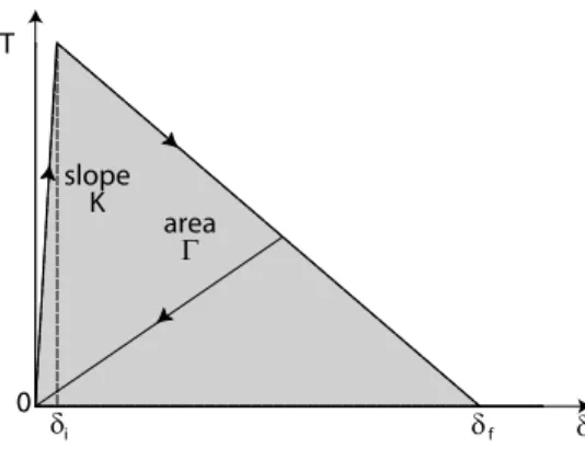
the filler/matrix adhesion a cohesive zone model as illustrated in figure 1 is used. [12] have reviewed numerous cohesive zone models and their specific abilities. The simplest cohesive zone model is used here, which relates the
nominal traction ~T at each point of the interface to the relative displacement
~
δ of the matrix with respect to the rigid particle at this point: ~
T = K.~δ if δ 6 δi
where δ is the modulus of ~δ,
~ T = K.δi δ. δf − δ δf − δi .~δ if δi < δ < δf
and ~T = 0 if δ > δf. The above equations apply when δ increases, and the
unloading process is described in figure 1. In other words, the interface is
elastic-damageable, with damage initiation when δ reaches δi and complete
failure obtained when δ = δf. Whatever the mixture of mode I and mode II,
complete failure is thus obtained when a fixed interface energy Γ = K.δi.δf/2
has been dissipated, and the above three-parameter model is a special case of the general approach of [13]. The highest value of K allowing convergence has been chosen.
3. Microstructure
Polydispersity can be represented by a continuum spectrum of particle size. To simplify this representation, in the current work, bidisperse mi-crostructures are considered. From a geometric viewpoint, particle bidisper-sity is described by two microstructural parameters: the ratio f of the total perimeter of small particles over the total perimeter of large particles in the
T δ δ δ 0 i f slope K area Γ
Figure 1: Shape of the force/displacement curve chosen as cohesive zone model.
cross section of the composite, and the ratio Q of the radius of small par-ticles over the radius of large parpar-ticles. Note that the product of the ratios f and Q is equal to the ratio of the surface fraction of small particles over the surface fraction of large particles. From monodisperse calculations, [10] has highlighted that the particles size has a significant effect on the failure behaviour considering small particles four times smaller than large particles for the chosen set of parameters. Therefore, the Q ratio will henceforth be fixed at a value of 0.25. This section reports the process developed to cre-ate random bidisperse microstructures so as to study the effect of f . An assessment of the randomness of the microstructures is also carried out. 3.1. Process for generating random bidisperse microstructures
Among several randomization schemes for creating a randomly oriented set of particles, [14] proposed to start from a square periodic lattice of par-ticles and to attempt random small displacements of each particle at each step of a numerical algorithm. An attempt is accepted when there is no over-lapping between particles in the resulting configuration. The displacement
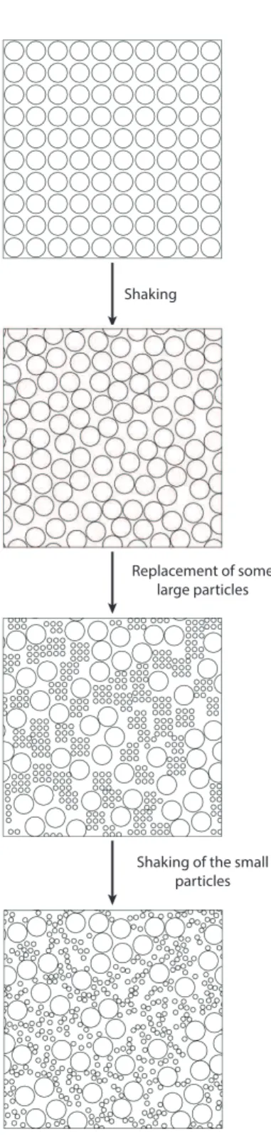
directions are random and the displacement length is set so as to obtain a 50% acceptance ratio. The scheme proposed in this work for bidisperse mi-crostructures is directly inspired from the work of [14]. It comes in 3 steps (figure 2): (1) direct use of the “shaking” algorithm on a lattice consisting in N particles of the same large size, (2) replacement, on a random choice
basis, of a large particle by a square periodic lattice of n2 smaller particles
and repeating this replacement for N − Nl large particles, (3) “shaking”of
the small particles lattice.
The representativity of the resulting cell containing small and large par-ticles randomly dispersed may be questioned. From practical considerations, two conditions seem necessary to obtain a periodic representative
elemen-tary cell from this scheme. First, the cell consisting in the Nl remaining
large particles (step 2) must be representative of a random monodisperse microstructure. According to [10], in the framework of solid propellant-like
models, this condition was verified for Nl = 49 and a sufficient number of
shakes was applied during step 1. Second, proper dispersion of the small particles must be ensured. The same reasoning as above is applied, except that large numbers of small particles are targeted. Thus, the number of small particles no longer raises question about dispersion, the number of “shakes” alone is significant in this case.
3.2. Assessment of microstructure randomness
Torquato [14] reviewed the many mathematical tools used to character-ize the randomness of a two-dimensional lattice of impenetrable particles.
Among them the two-point probability function S2 measures the probability
Shaking
Replacement of some large particles
Shaking of the small particles
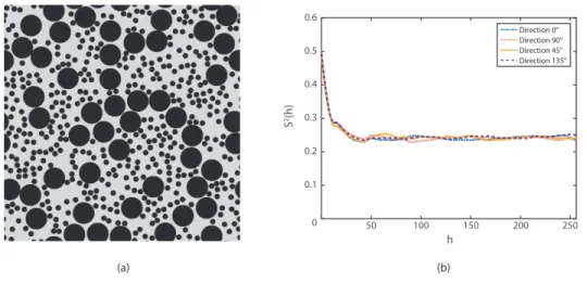
(a) h 50 100 150 200 250 S 2(h) 0 0.1 0.2 0.3 0.4 0.5 0.6 Direction 0° Direction 90° Direction 45° Direction 135° (b)
Figure 3: Example of a 2D bidisperse random cell with a 49.7% surface fraction of filler (a) and its autocorrelation function (b).
included in particles (either different or not). Applied on a typical bidisperse microstructure created by the proposed scheme (Figure 3.a), this probability function has been evaluated for four main directions in the plane (direction
0◦ is the horizontal axis in figure 3.a). This yields the results presented in
figure 3.b. From this curve, two main comments can be made. First, the value of the correlation function for h=0 is 0.497 whatever the direction.
This is consistent with the theory prediction: S2(0) provides the filler
sur-face fraction. Second, it is observed that the correlation function reaches a limit value that is 0.247 (i.e. the filler surface fraction squared) and does not depend on the direction. According to the theory, this is indicative of the randomness and geometric isotropy of the cell.
4. Implementation and discussion 4.1. Implementation
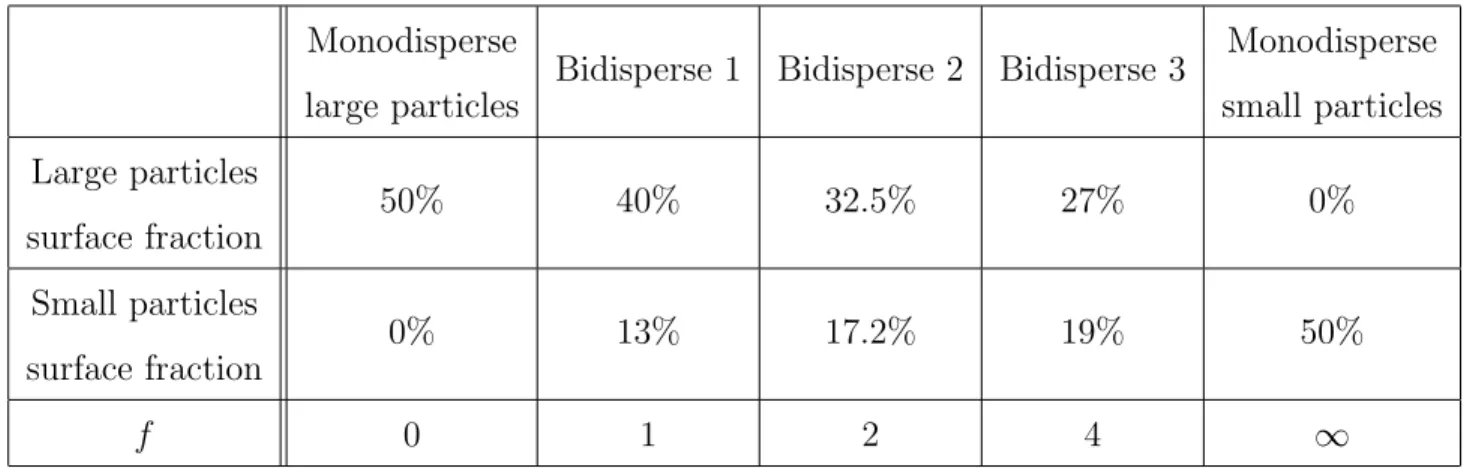
Due to the microstructure creating process, the filler surface fraction can-not be fixed but it is kept as much as possible close to 50%. On modifying the number of large and small particles, three values of the ratio f (total perime-ter of small particles over total perimeperime-ter of large particles) were chosen: 1, 2 and 4. For each ratio, eight different microstructures were generated and the composite mechanical behaviour is obtained by averaging the results on these eight microstructures. In each case, Q is 0.25 (see section 3), and the peri-odic cell contains 50 large particles. The other parameter values are chosen to mimic propellant-like behaviour in uniaxial tension: size of the large
parti-cles (0.42 mm), C0 = 2.2 MPa, K = 1500 MPa.mm−1, δi = 2.2x10⁻³ mm and
δf = 0.15 mm. Therefore Γ = 0.25 MPa.mm. Each microstructure is meshed
with around 700 000 plane strain hybrid four-node elements with reduced in-tegration. In order to account precisely for the interface damage the distance between two nodes at an interface is taken 15 times smaller than the interface
failure length δf. The absence of mesh dependency with this condition on
the cohesive zone length parameters was checked on microstructures consist-ing in an hexagonal array of particles. Uniaxial loadconsist-ing is applied with the Abaqus/Standard finite element code [15] with periodic conditions applied on the boundary of the cells through node-to-node displacement relations. The results of these calculations are compared to random monodisperse cal-culations using 49 particles of the same size, either small or large. The same constitutive parameters as above are applied. A synthetic description of the performed calculations on both monodisperse and bidisperse microstructures
Monodisperse large particles
Bidisperse 1 Bidisperse 2 Bidisperse 3 Monodisperse
small particles Large particles surface fraction 50% 40% 32.5% 27% 0% Small particles surface fraction 0% 13% 17.2% 19% 50% f 0 1 2 4 ∞
Table 1: Set of simulations performed
is given in table 1.
A failure criterion is applied to the results. It is based on both an ob-servation of the deformed microstructures obtained through finite element simulations and on insight about the mechanism of void coalescence in the material. During loading, it indeed is observed on deformed microstructures (see figure 4) that the debonding process commonly occurs in two steps. First, interface damage is moderate and homogeneously dispersed over the particles, then an instability appears along a branched strip of particles. In this zone, interface damage increases dramatically and highly stretched matrix fibrils appear. From a material viewpoint, rupture of the matrix is expected to occur in these fibrils. For that reason the appearance of this damage localization is chosen as a failure criterion for simulated microstruc-tures. Further justification of the relevance of this criterion is provided in [10].
(a) (b)
(c)
Figure 4: Evolution of a bidisperse random cell submitted to uniaxial tension. (a) Initial microstructure, (b) early damage occurring primarily around large particles, (c) further damage evolution with the appearance of matrix fibrils.
0 0.05 0.1 0.15 0 0.5 1 1.5 2 2.5 3 3.5 Engineering strain
Engineering stress (MPa)
0 0.5 1 1.5 2 2.5 3 3.5 Structure 1 Structure 2 Structure 3 Structure 4
Figure 5: Comparison of the uniaxial behaviours of four microstructures with the same parameters but with different particles layout
4.2. Results and discussion
First, the homogeneity of the chosen microstructures is tested. Figure 5 illustrates the uniaxial behaviours of four microstructures with the same parameters (f =2) except the particles layout was compared. It appears that the stiffness achieves very good repeatability, which is a necessary condition for homogeneousness whereas the failure is slightly scattered. Considering that failure depends on local layout of particles and that randomly dispersed microstructures are considered, this scatter is satisfactory. Such repeatability over the stiffness evolution and scatter over failure is a common feature of simulation results in this study. Thus, only failure scatter is represented henceforth, with a single uniaxial response shown.
The effect of the quantity of small particles interface is tested by varying the ratio f (total perimeter of small particles over total perimeter of large
0 0.05 0.1 0.15 0 0.5 1 1.5 2 2.5 3 3.5 Engineering strain
Engineering stress (MPa)
0 0.5 1 1.5 2 2.5 3 3.5 f=1 f=2 f=4
Figure 6: Comparison of the uniaxial behaviours of random bidisperse microstructures for different f ratios. 0 0.05 0.1 0.15 0.2 0.25 0.3 0.35 0 0.5 1 1.5 2 2.5 3 3.5 4 4.5 Engineering strain
Engineering stress (MPa)
0 0.5 1 1.5 2 2.5 3 3.5 4 4.5
Large particle only f=2
Small particles only
Figure 7: Comparison of the uniaxial behaviours of a random bidisperse microstructure with the uniaxial behaviour of monodisperse microstructures with either small or large particles.
particles). Figure 6 shows the mechanical behaviour recorded with random bidisperse microstructures for various values of f (see table 1 for description of the microstructures). Examining the composite behaviour and its failure, no significant effect of the f ratio is noted. Larger ratios f were not tested because they induced meshes exceeding one million elements, which was a computational limitation. As a consequence, the behaviour of the f = 2 composite is chosen as representative of the whole set of bidisperse composites in order to compare the effects of bidispersity and monodispersity on the behaviour in uniaxial tension.
Figure 7 draws a comparison between the behaviour of a representative random bidisperse microstructure and the behaviour of random monodis-perse microstructures with either the small or the large particles. First, the different initial slopes of the curves is commented. Given that the monodis-perse composites contain the same surface fractions of fillers, the difference in initial slope observed for these two composites is not a microstructural effect. Indeed, at a given strain, a higher displacement is experienced around the large particles than around the small particles. The elastic part of the cohesive zone model imposes therefore a higher stress around large particles. This explains the difference in the initial slopes. Second, dealing with the behaviour of the composites, the response of the bidisperse microstructures is intermediate in terms of stress and strain at failure between the two monodis-perse microstructure behaviours. As regards the microstructural evolution, in the case of the monodisperse microstructures with small particles, the appearance of a fibrillar zone is difficult to detect whereas it is straightfor-ward in the case of monodisperse microstructures with large particles. In
the bidisperse microstructures, as highlighted in figure 4, a “branching” of the fibrillar zone occurs: instead of occuring in the direction orthogonal to the loading as in monodisperse microstructures with large particles, the fib-rillar zone follows a tortuous path. The failure strain seems to be ruled by large particles, which is consistent with the failure mechanism underlined in figure 4. As this figure shows, the appearance of the void localization that characterizes failure is controlled by large particles. The presence of small particles in a bidisperse microstructure seems to have an effect mainly on the maximum stress experienced by the composite. This is consistent with the high levels of stress experienced by the monodisperse microstructures with small particles. This effect could be a consequence of the “branching” of the debonding localization direction. Indeed, as shown in figure 4, the localization direction is not merely orthogonal to the loading direction, but “branches”, presumably because of the clusters of small particles found along its path. Thus a larger amount of interface must be debonded, and therefore a larger amount of energy must be dissipated to achieve a given deformation of the composite. This translates into a higher level of stress.
5. Conclusion
A process to create periodic two-dimensional microstructures of bidisperse fillers randomly distributed in an elastomer has been proposed. This process consists in four steps : (1) creation of a square periodic lattice of large parti-cles, (2) randomization of this lattice, (3) replacement of some large particles with a square periodic lattice of smaller particles, (4) randomization of the small particle lattice. The randomness of the resulting microstructures has
been assessed with the two-point correlation function. Then, the proposed scheme has been used to create microstructures representing highly filled elastomers with micrometric fillers. A cohesive zone model was introduced to account for dewetting around the filler/matrix interface. The influence of the f ratio (total perimeter of small particles over total perimeter of large particles) on the mechanical behaviour of the composites in uniaxial tension was studied with finite element simulations. No significant effect of this pa-rameter has been observed for the considered values of f ranging from 1 to 4. The uniaxial behavior of the bidisperse microstructure has been compared to the behavior of monodisperse random microstructures containing either small or large particles. Using the appearance of a fibrillar microstructure as failure criterion, it has been noticed that the strain at failure seems to be ruled primarily by the dewetting around the large particles whereas the small particles have an impact on the stress at failure. This study based on a numerical modelisation of a highly filled elastomer provides insight on the mechanisms that occur at a microstructural scale during uniaxial tension. However, the predicted effect on failure lacks experimental validation. This is the subject of ongoing work.
Acknowledgements
Reference
[1] A. Davenas. Technologie des propergols solides. Masson, 1988.
[2] L. A. Vratsanos and R. J. Farris. A predictive model for the mechanical behavior of particulate composites. Part ii: comparison of model to literature data. Polymer Engineering and Science, 33:1466–1474, 1993. [3] A. N. Gent and B. Park. Failure processes in elastomers at or near a rigid spherical inclusion. Journal of Materials Science, 19:1947–1956, 1984.
[4] Z. J. Tao, S. D. Ping, Z. Mei, and Z. P. Cheng. Microstructure deforma-tion and fracture mechanism of highly filled polymer composites under large tensile deformation. In 12th International Symposium on Multi-scale, Multifunctional and Functionaly Graded Materials. IOP Science, 2013.
[5] H. M. Inglis, P. H. Geubelle, K. Matous, H. Tan, and Y. Huang. Cohesive modeling of dewetting in particulate composites: micromechanics vs. multiscale finite element analysis. Mechanics of Materials, 39:580–595, 2007.
[6] K. Matous, H. M. Inglis, X. Gu, D. Rypl, T. L. Jackson, and P. H. Geubelle. Multiscale modeling of solid propellants: From particle pack-ing to failure. Composites Science and Technology, 67:1694–1708, 2007. [7] X. A. Zhong and W. G. Knauss. Analysis of interfacial failure in
particle-filled elastomers. Journal of Engineering Materials and Technology,
[8] J. Segurado and J. Llorca. A computational micromechanics study of the effect of interface decohesion on the mechanical behavior of composites. Acta Materialia, 53:4931–4942, 2005.
[9] J. Moraleda, J. Segurado, and J. Llorca. Effect of interface fracture on the tensile deformation of fiber-reinforced elastomers. International Journal of Solids and Structures, 46:4287–4297, 2009.
[10] P.-A. Toulemonde, J. Diani, P. Gilormini, and N. Desgardin. On the account of a cohesive interface for modeling the behaviour until break of highly filled elastomers. Submitted, 2015.
[11] X. A. Zhong and W. G. Knauss. Effects of particle interaction and size variation on damage evolution in filled elastomers. Mechanics of Composite Materials and Structures, 7:35–53, 2000.
[12] K. Park and G. H. Paulino. Cohesive zone models: a critical review of traction-separation relationship across fracture surfaces. In Applied Mechanics Review, 2011.
[13] V. Tvergaard and J. W. Hutchinson. The influence of plasticity on mixed mode interface toughness. Journal of the Mechanics and Physics of Solids, 41:1119–1135, 1993.
[14] S. Torquato. Random Heterogeneous Materials. Springer, 2002.
[15] Abaqus/Standard. Dassault Syst`emes Simulia Corporation. Providence,