Direction des bibliothèques
AVIS
Ce document a été numérisé par la Division de la gestion des documents et des archives de l’Université de Montréal.
L’auteur a autorisé l’Université de Montréal à reproduire et diffuser, en totalité ou en partie, par quelque moyen que ce soit et sur quelque support que ce soit, et exclusivement à des fins non lucratives d’enseignement et de recherche, des copies de ce mémoire ou de cette thèse.
L’auteur et les coauteurs le cas échéant conservent la propriété du droit d’auteur et des droits moraux qui protègent ce document. Ni la thèse ou le mémoire, ni des extraits substantiels de ce document, ne doivent être imprimés ou autrement reproduits sans l’autorisation de l’auteur.
Afin de se conformer à la Loi canadienne sur la protection des renseignements personnels, quelques formulaires secondaires, coordonnées ou signatures intégrées au texte ont pu être enlevés de ce document. Bien que cela ait pu affecter la pagination, il n’y a aucun contenu manquant.
NOTICE
This document was digitized by the Records Management & Archives Division of Université de Montréal.
The author of this thesis or dissertation has granted a nonexclusive license allowing Université de Montréal to reproduce and publish the document, in part or in whole, and in any format, solely for noncommercial educational and research purposes.
The author and co-authors if applicable retain copyright ownership and moral rights in this document. Neither the whole thesis or dissertation, nor substantial extracts from it, may be printed or otherwise reproduced without the author’s permission.
In compliance with the Canadian Privacy Act some supporting forms, contact information or signatures may have been removed from the document. While this may affect the document page count, it does not represent any loss of content from the document.
Université de Montréal
Formulation of Emulsion Systems for the Preparation
of
But
yi
Rubber Gloves
Par
Sen Ge
Département de chimie
Faculté des arts et des sciences
Mémoire présenté
à
la Faculté des études supérieures en vue de l'obtention
du grade de Maîhise en chimie
June 2009
Sen Ge
Université de Montréal
Faculté des études supérieures
Ce mémoire intitulé
Formulation
of Emulsion
Systems for the Preparation
of Butyl Rubber Gloves
Présenté par
Sen Ge
à
été évalué par
unjury composé des personnes suivantes:
Président rapporteur
Directeur de recherche
Résumé
Les gants résistants aux produits chimiques sont fabriqués industriellement à partir d'une grande variété de matériaux comme le nitrile, le néoprène, le PVC ou une combinaison de ces matériaux. Le défi posé pour fabriquer des gants avec le polybutyle est que celui-ci est déjà sous la forme d'un polymère, alors que les autres matériaux sont des émulsions aqueuses non polymérisées. En conséquence, lors de la fabrication traditionnelle de gants en caoutchouc butylique, une grande quantité de solvant organique, comme le toluène, est utilisée. Le toluène est un solvant toxique pour l'humain et l'environnement. Le choix d'un solvant non toxique, comme l'eau, est désiré. Mais l'eau ne peut pas dissoudre le caoutchouc butylique et une solution possible à ce problème reste la préparation d'une émulsion huile dans l'eau pour la solubilisation du polymère butyle.
Nous avons préparé des émulsions ternaires d'eau, de caoutchouc butylique et de solvant organique en optimisant la teneur en eau et en minimisant la quantité de solvant organique pour une concentration maximum de caoutchouc butylique. L'émulsion doit avoir une bonne stabilité et une viscosité appropriée. Le diagramme de phases ternaire montre le domaine de stabilité des différentes compositions en eau, caoutchouc butylique et solvant. Les solvants organiques étudiés sont le toluène, l'hexane et l'isooctane.
La rhéologie est utilisée industriellement pour suivre l'évolution de la concentration de l'émulsion lors de la fabrication de gants. Les effets du taux de cisaillement sur la viscosité ont été étudiés. La viscosité a servi à définir les domaines et types d'émulsions stables dans le diagramme de phases. Les deux types d'émulsions (huile-dans-eau et eau-dans-huile) ont des propriétés rhéologiques très différentes, domaines de valeurs d'environ 15 Pa.s comparés à environ 1500 Pa.s. Les propriétés mécaniques du caoutchouc butylique ont été étudiées par la méthode d'analyse mécanique dynamique.
Abstract
Chemically resistant gloves have been made by a variety of polymers such as nitrile rubber, neoprene, poly(vinyl chloride), or combinations of these materials in industry. But yi rubber is the most commonly by utilized material to make rubber gloves. Unlike other kinds of rubber gloves which can be made by an emulsion polymerization process, a large amount of organic solvent such as toluene has to be used to solubilize the rubber in the traditional procedure ofmaking but yi rubber gloves. Toluene is considered as a toxic solvent to human health and to the environment. A water-based system would be more desirable. Since but yi rubber cannot be dissolved in water, an emulsion system with a suitable organic solvent may be used.
We have prepared and optimized but yI rubber-organic solvent-water temary emulsion systems with the help of suitable surfactant(s) for dissolving the maximum amount of but yI rubber in the emulsion. This type of emulsion maintains a good stability and a suitable viscosity. An optimized composition of the emulsion system was determined by ternary phase diagrams. The organic solvents studied include toluene, hexane, and isooctane.
Rheology is used to follow the evaluation of concentration of emulsion in the manufacturing of the glove. The effect of shear rate on the viscosity was studied, since the thickness of but yi rubber gloves is affected by the viscosity. The viscosity measurements were used to define the various zones in the phase diagram of the different types of emulsions. The viscosity of the oil-in-water emulsion is around 15 Pa.s, while that of the water-in-oil emulsion is around 1500 Pa.s. Dynamic mechanical analyses were used to evaluate the mechanical properties of but yi rubber gloves.
Table of contents
Résumé··· ... ···1 Abstract··· ... II Table of contents···111 List of figures···V List of tables ... ···Vll List of symbols and abbreviations···VIIl Acknowl edgements··· ·IX 1. Introduction ... 11.1. General industrial rubbers ... 1
1.2. But yI rubber ... 1
1.2.1. Background ... 1
1.2.2. Properties and applications ... .3
1.3. Rubber Gloves ... 4
1.3.1. Selection of rubber gloves ... 5
1.3.2. Preparation of rubber gloves ... 8
1.3.3. Stable emulsion for making but yi rubber gloves ... 9
1.3.3.1. Selection of surfactants ... 9
1.3.3.2. Selection of co surfactants ... 13
1.3.3.3. Ca1culation ofviscosity ... 14
1.3.4. Molding of rubber gloves ... 16
1.4. Objectives of the project ... 17
References ... 18
2. Experimental procedures ... 27
2.1. Materials ... 27
2.2. Preparation of sampI es ... 28
2.2.2. Phase diagrams ... 29
2.2.3. Procedure ofvulcanization ... 31
2.3. Instruments and measurements ... 32
2.3.1. Viscosity ... .32
2.3.2. Dynamic mechanical analysis (DMA) ... 34
2.3.3. Fourier transform infrared (FTIR) spectroscopy ... 34
2.3.4. Nuclear magnetic resonance (NMR) spectroscopy ... 35
References ... 35
3. Results and discussion ... 37
3.1. Raw material ofbutyl rubber ... 37
3.2. Emulsion preparation ... 42
3.2.1. Process development. ... 42
3.2.2. Effect of the type of organic solvent.. ... .44
3.2.3. Effect of the type of surfactant... ... .45
3.2.4. Effect of the surfactant concentration ... .48
3.2.5. Effect of agitation ... 5 J 3.2.6. The viscosity of the emulsion ... 54
3.3. Preparation but yI rubber films ... 61
3.3.1. Vulcanization ... 61
3.3.2. Effect of dipping speed ... 62
3.3.3. Mechanical property test. ... 64
References ... 66
4. Conclusions ... 69
Appendix .. ... 72
A. Synthetic Method of But yi Rubber ... 72
B. Mooney viscosity ... 76
C. Viscosity measurements ... 76
Figure 1.1 Figure 1.2 Figure 1.3 Figure 1.4 Figure 2.1 Figure 2.2 Figure 3.1 Figure 3.2 Figure 3.3 Figure 3.4 Figure 3.5 Figure 3.6 Figure 3.7
List of figures
The structure of but yI rubber Three modes of isoprene addition. Oil-in-water emulsion
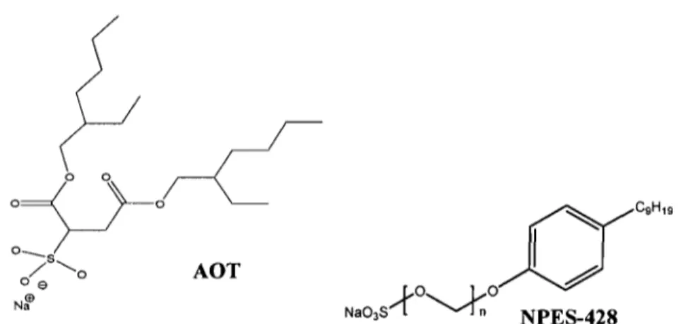
The structure of sodium bis(2-ethylhexyl) sulfosuccinate (AOT) and poly( oxy-l ,2-ethanediyl),
alpha-sulfo-omega-(nonylphenoxy)-,sodium salt (NPES-428) Schematic of construction for a ternary diagram.
Schematic diagram of the cone-and-plate geometry for rotational rheometer.
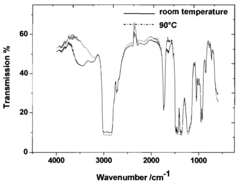
FTIR spectra ofbutyl rubber at room temperature and 90°C.
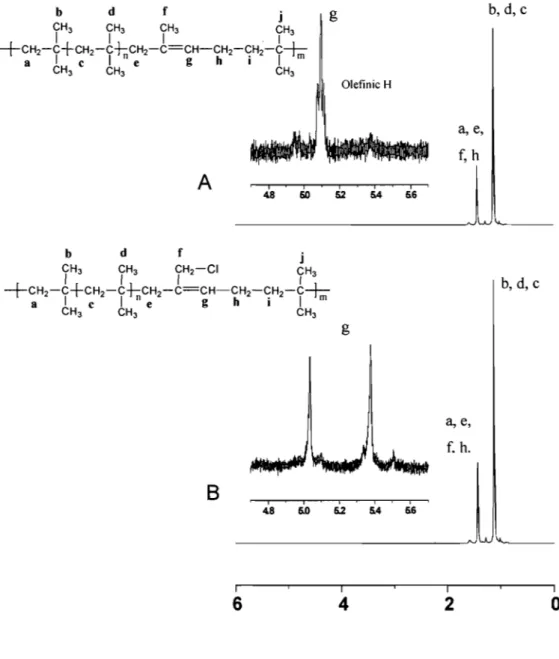
1 H NMR spectra of but yI 065 (Figure 3.2-A) and of chlorobutyl
rubber (Figure 3.2-B) in CDCb at room temperature (Both materials were obtained from ExxonMobil.).
Water-in-oil emulsion and Oil-in-water emulsion
Phase diagrams of but yi rubber-organic solvent-aqueous systems under different conditions. A: Toluene system with AOT as the surfactant; B: Hexane system with AOT as the surfactant; C: Hexane system with NPES-428 as the surfactant. A series of ternary phase diagrams of the hexane system, prepared with different concentrations of the surfactant (NPES-428) in the aqueous phase.
A. Ultra Turrax homogenizer. B. Cross section of an emulsifying machine (Ultra Turrax homogenizer).
A. Emulsion mixed by the homogenizer; B. Sample mixed by the magnetic stirring with phase separation at the bottom.
2 3 10 13 31 33 39 40 46 47 51 53 53
Figure 3.8 Variation ofviscosity as a function of the shear rate for an 56 example of a stable emulsion (T204). A. Fitting of the viscosity
data with three viscosity models; B. Figure enlarged
Figure 3.9 Zero-shear rate viscosity as a function ofpercentage of the 58 aqueous phase containing water and surfactant (AOT).
Solid line: the Carreau Model; dotted line: the Carreau-Yasuda Model.
Figure 3.10 The water-in-oil emulsion area and the oil-in-water emulsion 59 area shown in the temary phase diagram.
Figure 3.11 The variation of the zero-shear rate viscosity of a temary system 60 containing but yI 065 as a function of the percentage of the
aqueous phase.
Figure 3.12 A. The viscosity as a function of the testing time. 63
B. The viscosity as a function of the shear rate.
Figure 3.13 Dynamic mechanical analysis (DMA) ofrubbers as a function of 65 temperature. A. tano (storage modulus E' divided by loss
modulus E"), B. Log storage modulus.
Figure 4.1 The temary phase diagram shows the different areas. 70
Figure A.l Chain transfer to monomer during the synthesis of but yI rubber 73
Figure A.2 Termination with counter-ion in the preparation of but yI rubber 73
Figure A.3 Termination by hydride donor during the synthesis of but yI 73 rubber
Figure A.4 Involving isoprene derived chain-ends 74
Figure A.5 Structures of isoprenyl units in bromobutyl rubber 75
Table 1.1 Table 1.2 Table 3.1 Table 3.2 Table 3.3 Table 3.4 Table 3.5
List of tables
Examples of glove recommendation.
HLB values and properties, and applications of surfactants. Specifications ofbutyl rubbers from Exxon.
Assignment of IH NMR signaIs of the butyl rubber sample. Solubility of but yI rubber in organic solvent.
Viscosity models and fitting parameters calculated from the viscosity data for selected sample tested.
Chemical composition of selected samples used for viscosity measurements. 6
12
37
41 44 55 57Table 3.6 Compositions (wt%) ofbutyl rubber-water-solvent temary systems 64 used for the preparation of the samples for the DMA.
Table C.1 Viscosity data and fitted parameters calculated by the Cross model 76 for selected emulsion samples.
Table C.2 Viscosity data and fitted parameters calculated by the Carreau 77 model for selected emulsion sampI es.
Table C.3 Viscosity data and fitted parameters calculated by the Carreau- 77 Yasuda model for selected emulsion samples.
List of symbols and abbreviations
AOT Sodium bis(2-ethylhexyl) sulfosuccinate
NPES-428 Poly( oxy-l ,2-ethanediyl), alpha-sulfo-omega-(nonylphenoxy)-, sodium salt TMTD DMA FT-IR NMR CMC HLB l'1Gm(l) l'1Gm(h) NALP S H N 1'/0
r
À. Tetramethylthiuram disulfide Dynamic mechanical analysis Fourier transform infrared Nuclear magnetic resonance Critical micelle concentration Hydrophile-lipophile balance Free energy of m icell izationFree energy of the hydrophilic moiety Non-aqueous liquid phase
Shear stress Viscosity Shear rate
Flow behaviour index
Limiting viscosity at high shear rates Zero-shear rate viscosity
Shear rate
Acknowledgements
This research was funded in part by the BEST GLOVE, Inc., and in part by l'Institut de recherche Robert-Sauvé en santé et en sécurité du travail (IRSST).
J would like to express my sincere gratitude to my thesis supervisor, Dr. Julian Zhu of the Department of Chemistry at Université de Montréal, for his scientific training and supervision, his great help and advices for this thesis preparation.
1 wish to thank sincerely Dr. Jaime Lara for his kind help with the correction of the papers in this thesis.
The author thanks the other members of our group: Gérald Perron, Dr. Ya Cao, Dr. Qiang Wu, Florence Janvier, Guillaume Giguère, Yujuan Wang, Bao Toan Nguyen, Héloïse Thérien-Aubin, Julie Boivin, Sylvain Essiembre, Jie Zhang, Gwénaëlle Bazin, Cindy Charboneau, and Claire Jaubert.
My family has provided the spiritual support that is even more important. I
1. Introduction
1.1. General industrial rubbers
Rubber is an elastic polymer that exhibits unique physical and chemical properties; it is set apart from other solids due to its characteristic elastic or thermoelastic behavior.1 In nature it exists as a milky col1oid, known as latex, suspended in the sap of several varieties of plants? The major commercial source of natural rubber is from Para rubber trees that grow in tropical areas. Nearly 22.7 million tons ofrubber was produced in 2007, ofwhich around 42% was natural rubber. Rubber products are forecast to increase by 4 percent annually. The aqueous synthetic latex process is not flammable and has little odor.3 Based on demand, up to fourteen types of
....
rubber are commonly used in various industrial applications.4 Sometimes it is necessary to mix different kinds of rubber together, resulting in a material with special characteristics. The composition of rubber mixtures determines in large part their rheological and mechanical properties.5
1.2. Butyl rubber
1.2.1. Background
ln 1942, but yi rubber was first produced as a commercial product. In 1944, Polysar, a Canadian company, began to produce but yi rubber in Sarnia, Ontario. In 1991, Bayer purchased aU the Polysar installations.6 At the same time, ExxonMobil obtained the authorization for aH production in France. Hence, the production of but yI rubber was monopolized by ExxonMobil and Bayer. ln the 1950s and 1960s,
halogenated but yI rubber was developed in its chlorinated and brominated variants, providing significantly higher curing rates and allowing covu1canization with other rubbers such as natural rubber and styrene-butadiene rubber.7 Halobutyl rubber is today the most important material used for inner tubes.8
But yI rubber is a generic name for a family of isobutylene-isoprene copolymers, that typicallY contains about 98% polyisobutylene with 2% isoprene distributed randomly on the polymer chain (Figure 1.1).9 lt is a colourless, semi-solid elastomer.9 Problems associated with performing a detailed analysis of but yi rubber were largely due to the presence ofthis very small amount of the isoprene units in the pOlymer.1O
Figure 1.1. The structure of but yi rubber
The copolymerization of isobutylene with diolefins has been explored over the years.lO fsobutylene-based elastomers are valued for their excellent air retenti on, heat and steam resistance, ozone and weathering resistance, and outstanding dampening characteristics.11 The long segments of polyisobutylene polymer chains provide good mechanical properties because of the flexibility of their chains. This type of rubber has many applications because of its special characteristics.9 As with ail copolymers, their physical and chemical properties depend on how the diolefin units enter the polymer chain. Therefore, a study of the percentage of the isoprene units is important, as it can affect the physical and chemical properties of but yI rubber.12 But yI rubber is defined
both by the structure of the monomeric residues and the mode oftheir incorporation in the isobutylene-isoprene copolymers.13 ln general, their incorporation can be defined by the following features:
(a) Mode of incorporation ofisobutylene units (head-to-tail or head-to-head), (b) Mode of incorporation of isoprene units (1,4, 1,2, or 3,4, and head-to-tail or head-to-head),
(c) Distribution of isoprene units (random or block), (d) Configuration ofincorporated isoprene units (Z or E).9
There are three possible structures that can represent the mode of isoprene addition (Figure 1.2):
(l) 1,4 addition (2) 1,2 addition (3) 3,4 addition
Figure 1.2. Three modes of isoprene addition.14
1.2.2. Properties and applications
The major advantages of but yi rubber are low gas permeability, thermal and oxidative stability, excellent moisture and chemical resistance. But yi rubber has become widely used for inner tubes, tire inner liners, inner tubes for footballs, stoppers for medicine bottles, sealants and adhesives, o-rings, joint replacements, chewing gum, tank liners, speaker surrounds, and rubber tire-curing bladders.9 Despite these unique
properties, there are some deticiencies associated with this polymer, mainly its poor compatibility with other materiaIs, including elastomers, plastics and carbon black.2
When but yI rubber is synthesized, high molecular weights can be obtained at a temperature of approximately -75°C. The detailed synthetic method of but yi rubber is given in the appendix. The isobutylene monomer should be cooled to -75°C in the tirst step of the synthesis; the initiator and co-initiator system is effective in non-aqueous sol vents in a temperature range of -100°C to -20°C. Therefore, the making of but yi rubber products is controlled by temperature; this low temperature (-75°C) is easy to reach in the laboratory, but is difficuIt to obtain in a commercial setting.
Commercial halobutyl (chloro or bromo) rubbers are more easily vuIcanized than but yi rubber.15 Chlorobutyl and bromobutyl derivatives of but yI elastomers are of greater commercial importance.8
1.3. Rubber Gloves
ln industry, protective gloves play an important role in handling sol vents because of their special properties and applications, there is demand for but yI rubber gloves.16 There are many ways to make rubber gloves, but industrial suppliers are looking for an environmentally friendly and easy method. In the most commonly used process for making gloves, but yI rubber is tirst dissolved in an organic solvent in order to prepare a solution, followed by a dipping step. In the dipping step, a metal hand-mold is immersed in the rubber solution. The polymer adheres to the mold's surface, and the viscous solution taking the form of a hand. This is followed by a vulcanization process that can crosslink the polymer chains. A large amount of organic solvent has to be used in this process. Driven by envi ronm entai and heaIth concems, industrial suppliers
'"
intend to find new water-based methods to make protective gloves from but yi rubber. This is the major challenge ofthis research project.
1.3.1. Selection of rubber gloves
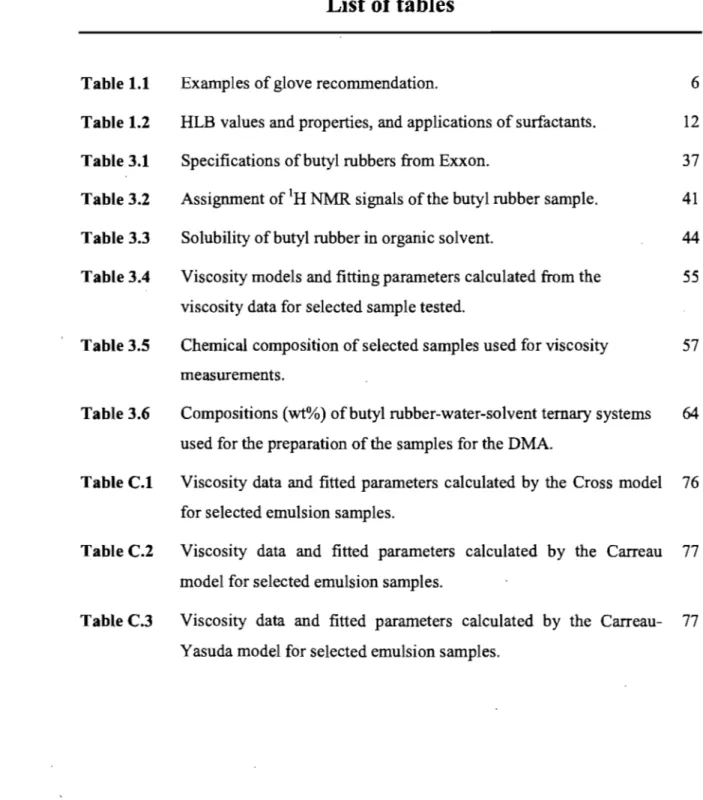
Chemically resistant gloves can be made from a variety of materials such as natural rubber or latex, but yi rubber, neoprene, nitrile rubber, poly(vinyl chloride) (PVC), and poly(vinyl alcohol) (PVA). Chemical resistant gloves are not totally "chemical-proof'. No rubber glove can resist even a single chemical agent forever. There is no one kind of "ideal" chemically resistant glove that can prote ct workers from ail kind of chemicals. Chemicals will eventually penetrate the gloves over time by swelling, cracking or weakening of the glove material. Chemicals can pass through a protective glove ev en if the material does not contain pinholes or pores. The chemical can diffuse through the material at the molecular level without leaving any physical change observable to the human eye. Table 1.1 provides a general guideline for the selection of rubber materials required for handling particular solvents. The barrier effectiveness of synthetic rubber gloves is not as weil established as for latex gloves.17 The correct glove can protect the skin from contact with damaging chemicals, white an improper choice may incur serious damage such as chemical bums, dennatitis, intoxication, or risk of cancer.
Table 1.1. Examples ofglove recommendationlS-23 Solvent Acetone Benzene Ethanol Gasoline Hexane Isopropanol Mesitylene Methyl cellosolve Methyl ethyl ketone Methyl isobutyl ketone Naphtha To/uene To/uene diisocyanate 1, I, I-Trich/oroethane Turpentine Xy/ene
Recommended glove material But y/ rubber, Polythene rubber
PVA, Viton®(tluoroelastomer)a, Polyurethane rubber, Neoprene rubber
But yi rubber, Nitrile rubber, Neoprene, Natura/ rubber, Viton®
polyvinyl a/coho/ (PVA b), Nitrile rubber Viton®, Neoprene, PV A b, Nitrile rubber
Natura/ rubber, Neoprene, Nitrile rubber, po/yviny/ ch/oride (PVC)
PVA, Viton® But yI rubber, PV Ab
But yi rubber, PV Ab, Viton®, Polythene rubber PVA
Polyurethane rubber, Nitrile rubber PV Ab, Viton®,
PVAb
Viton®, Natura/ rubber, Po/ythene rubber PV Ab, Nitrile rubber
PVA b, Nitrile rubber
a Viton® is a tluoroelastomer. It has excellent heat resistance (200°C). F/uoroelastomers are used in a wide variety of high-performance applications. The main tluoroe/astomers are shown be/ow:
b. Po/yvinyl acetate (PV A) -t-CF2-CF
-tnt
CH2- CF2+m 1 CF3 Copo/ymer tluoroe/astomer -+CF2-CFintCH2-CF2+mt-CF2-CF2""7j-1 CF3 Terpolymer tluoroe/astomerImproved low temperature tluoroelastomer terpolymer
Non- VF2 tluoroelastomer terpolymer
Four examples can be given to explain the importance of choosing the correct rubber glove. Natural latex rubber resists acids, alkalis, salts, and ketones. Latex is also blended with other polymers to make a combination glove which protects against several organic solvents. Neoprene gloves are suited for petrochemicals as they are resistant to acids, alcohols and oils. Nitrile rubber is a synthetic rubber that will not swell in aromatic sol vents and petroleum solvents. Poly(vinyl chloride) (PVC) resists acids and alcohols, but will be weaken in petroleum solvents. To summarize, every kind of rubber glove has its specific purposes. 8ased on the chemicals to be used, us ers should select the correct rubber gloves for their application.
The synthesis of nitrile rubber is easy to control at room temperature.24 Therefore, nitrile rubber gloves can be easily made by emulsion polymerization, since they can take their shape during the process of synthesis. However, but yi rubber must be synthesized at a very low temperature (-75°C) which creates a problem in commercial production. Another method than the emulsion polymerization process has to be found to make but yi rubber gloves.
Allergie reactions are another consideration in the selection of chemical protective gloves. There are three major types of reactions that affect the health of the worker:
immediate reaction, irritant dermatitis and delayed cutaneous hypersensitivity. It is important to consider the risk of allergie sensitization when selecting gloves, rather than just choosing the lowest cost item available. Even cornstarch powder, long used in rubber gloves to help conserve the rubber, can also cause allergies to sorne users,z4
The last consideration is priee. In general, natural latex rubber gloves are cheaper than synthetic rubber gloves, but the priee also depends on the technology of production.
1.3.2. Preparation of rubber gloves
The emulsion polymerization process used in making rubber is not suitable for but yi rubber because of the low temperatures requirement. It may be possible to develop a process for making rubber gloves by dipping into an emulsion containing but yi rubber. The tirst step is to prepare a polymer emulsion, which includes the polymer, water, an organic solvent if necessary, and sorne additives. Typically, the concentrated emulsion includes polymers (around 30-60 % of the emulsion) and water along with various stabilisers, dispersing agents, vulcanisation agents, accelerators, activators, antioxidants and other compounding ingredients. Approximately 5 % of the weight of the tinished product consists of chemicals added during the preparation of the emulsion.25
The prepared emulsion is then pumped into a dipping machine.22 G10ves are formed on glove-shaped porcelain molds (formers) mounted on a continuous chain that moves through the emulsion dipping tank. The formers are tirst cleaned, using either acidic or alkaline solutions, and then heated before pre-treatment with a coagulant such as calcium nitrate.'8 The formers are th en dipped into the bath, and a uniform film is
deposited. The coagulant con verts the emulsion from a liquid to a solid. At the same time, a film is formed on the mold?Z The formers then pass through warm water baths (leaching tanks) to rem ove water and excess additives.19 Finally, the gloves are passed through vulcanisation ovens at approximately 80-90°C. Here, the polymers are crosslinked to improve the product's mechanical property.
Jn industry, but yi rubber gloves cannot be formed using the polymerization step, because but yi rubber must be synthesized at a temperature lower than -70°C. High temperatures cause the initiator and co-initiator system to take effect immediately, resulting in a reaction which is too fast to be controlled. The dipping procedure has been used for making but yi rubber gloves from a solution of but yi pol ymer in an organic solvent (toluene). When a mold is dipped into the polymer solution, the polymer adheres to the mold surface. The organic solvent is then vaporized at a high temperature, and the but yi rubber glove is formed on the mold. The whole process can be completed in a short time, but a large amount of organic solvent is needed.
The use of organic solvent has serious health and safety concerns, as weil as environmental concerns. Therefore, an emulsion in a water-based solvent system would be an interesting alternative to address such concerns.
1.3.3. Stable emulsion for
ma king but yI rubber gloves
1.3.3.1. Selection of surfactants
An emulsion is a mix of two or more immiscible substances dispersed in each other. ln the emulsion, the phase interfaces scatter the light. For this reason, they have a cloudy appearance.Z6-Z8 [n general, emulsions cannot form spontaneously and tend to
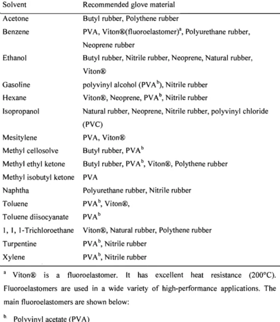
phase separate with time. An emulsifier (also called a surfactant) is a substance that stabilizes an emulsion. In general, there are water-in-oil emulsions (W/O emulsions) and oil-in-water emulsions (O/W emulsions) (see Figure 1.3). The type of emulsion depends on the relative volume of both phases and the surfactant. In a water-in-oil emulsion, the quantity of oil phase is more than the quantity of water phase. Inversely, an oil-in-water emulsion has the water phase larger than the oil phase. For this project, an oil-in-water emulsion should be prepared, because a water-based system is environmentally friendly. To obtain an oil-in-water emulsion of but yI rubber polymer, a water-surfactant mixture may be gradually added to a solution that includes but yI rubber and an organic solvent.
~
Aqueous Solutiono-v'
Surfactant monomer Organic compound
Figure 1.3. Oil-in-water emulsion.29
Oil
Surfactant micelle
Surfactants are amphiphilic compounds that can change the properties of fluid interfaces in an emulsion. Different types of surfactants are used for different organic sol vents (oil phase). The hydrophile-lipophile balance (HLB) number is a measure of
the relative effect of the surfactant and can be used to characterize the relative affinity of surfactants for aqueous and organic phases.3o The value of HLB is obtained by
(1)
where L'iGm(/) is the fraction of the free energy of micellization associated with the
hydrophobic moiety,31 L'iGm(h) the free energy of the hydrophilic moiety,32 Cl and C2
two scaling factors that can be found from literature,33,34 R a gas constant, and T the temperature.
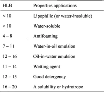
The HLB value can directly affect the type of emulsion obtained. Before the experiment, the range of HLB values of the surfactants should be examined. A high HLB number generally indicates that the surfactant can be well dissolved in water, while a low HLB number indicates a low aqueous solubility and high relative affinity for the organic phase. Water-in-oil emulsion needs a surfactant with a low HLB number, and oil-in-water emulsion needs a surfactant with intermediate to high HLB number. One of the objectives of this project is to maximize the water content in the emulsion system. Therefore, a surfactant with a high HLB value should be used for making oil-in-water emulsion. A HLB value of 10 is a turning point for emulsion preparation; when the HLB is higher than 10, oil-in-water emulsion can be prepared easily. Water-in-oil emulsion is relatively easy to make with a surfactant with a HLB value less than 10. The solubility of an emulsifier in water increases as its HLB value increases. As the HLB value increases, the dispensability of that compound in water increases along with the clarity of the solution that is formed (see Table 1.2).
Table 1.2. HLB
val~es
and properties, and applications of surfactants.35, 36 HLB Properties applications<10 Lipophilic (or water-insoluble) >10 Water-soluble 4-8 Antifoaming 7 -11 Water-in-oil emulsion 12-16 Oil-in-water emulsion 11-14 Wetting agent 12 - 15 Good detergency 16 - 20 A solubility or hydrotrope
As shown in Table 1.2, oil-in-water emulsion is easy to prepare with a surfactant that has a high HLB value (more than 10).37 Another criterion for choosing a surfactant is based on the type of organic solvent to be used. In this study, two kinds of surfactant were selected (AOT and NPES-428, ionic surfactants, see Figure 1.4).
AOT is a twin-tailed anionic surfactant with a very high HLB value (13.8). It has one hydrophilie head and two branches of hydrophobie tails, and it is often used to reduce the dispersion of interfacial tensions between two phases. AOT has been widely used in both research and technologieal applications since AOT is very soluble in water in the absence of any cosurfactant.38 Poly(oxy-1,2-ethanediyl), alpha-sulfo-omega-(nonylphenoxy)-, sodium salt (NPES-428) is an oil-in-water emulsifier with a recommended usage level of 0.5-5 %. The HLB value ofNPES-428 is 14.6.
Figure 1.4. The structure of sodium bis(2-ethylhexyl) sulfosuccinate (AOT) and Poly( oxy-l ,2-ethanediyl), alpha-sulfo-omega-(nonylphenoxy)-, sodium salt (NPES-428)
1.3.3.2. Selection of cosurfactants
A cosurfactant is often used to increase the effect of a surfactant. The cosurfactant induces changes in the interfacial film curvature between the organic solvent and the water.39 Cosurfactant contributes to reduce the interfacial tension to very low values by increasing the lipophilicity of the surfactant system.
Alcohol is often used as a cosurfactant. Alcohol has the ability of both increasing the non-aqueous phase liquid solubility in water and decreasing the oil-water interfacial tension by increasing the tlexibi1ity of the interfacial film and by interacting with either the head-group or the tail-group region of the surfactant.40 The critical micelle concentration (CMC) of the surfactant can be decreased effectively with a cosurfactant. The number of micelles may increase because of a lower CMC value. If the surfactant has a long tai! (hydrophobic group), the solubility of the surfactant in water may be
lower than the CMC, so that neither micelles nor microemulisons can form.41 However, the alcohol additives can successfully stabilize micelles in water-surfactant-oil systems by decreasing the CMC, although it is not an essential compound for every emulsion system. The type of cosurfactant should be considered when the surfactant has been selected.
1.3.3.3. Calculation of viscosity
Viscosity may be used to define an emulsion system. The oil phase in this study contains but yi rubber and organic solvent. The viscosity of the emulsion depends on the content of but yi rubber. But yi rubber gloves cannot be made by an emulsion with very high viscosity (water-in-oil emulsion), because the thickness of the glove would not be easy to control. The viscosity is one of the important criteria for choosing an appropriate emulsion. It helps define water-in-oil emulsion area and oil-in-water emulsion area in the ternary phase diagram.
Most concentrated emulsions show shear rate-dependent non-Newtonian type shear-thinning behavior at low and intermediate shear rates.42 On the contrary, the viscosity of the emulsion is stable (constant) at high shear rates. The viscosity of a Newtonian fluid is independent of shear rate, while that of a non-Newtonian fluid is not.43 To measure the viscosity, a certain force may be appIied to the fluid. This force is called yield stress and can correlate with other properties of a suspension. Newtonian fluids and non-Newtonian fluids can be distinguished by a power law (the Ostwald-de Waehle power law). lt is a useful and simple mathematical relationship (Equation 2) that describes the behavior of a fluid:44
(8U)n
S=1]
-8y (2)
where sis the shear stress, 1] viscosity of the material (Pa·sn), 8~ the shear rate (S·I),
and n the flow behaviour index (dimensionless). The type offluid can be defined by the behaviour index (n).45 If n<l, this fluid is pseudoplastic; if n=l, the material is a Newtonian fluid; if n> l, the sample is dilatant.46
Power law is suitable for generalized Newtonian fluid (Equation 2), which is an idealized fluid that has a constant viscosity value at different shear rates.47 The rheological properties of a fluid can be characterized in many ways. Numerical analysis such as curve-fitting may be used to obtain values of the parameters that characterize the fluid. There are many viscosity models to describe a shear-thinning fluid, such as the Cross mode]
(3)
.
where 1],,, is the limiting viscosity at high shear rates, 1]0 the zero-shear rate viscosity,
r
the shear rate, and Ca coefficient.48 The Carreau model is expressed as(4)
where À. is a time constant ca\culated from the reciprocal of the strain rate at which the zero strain rate component and the power-Iaw component of the flow curve intersect.43, 44 The Carreau model suits shear-thinning fluid. The Carreau-Yasuda model49, 50
n-1
'7 = '70
[1
+ (À ;t
r~-
(5)where À. is the calculated time constant, '70 the viscosity at zero-shear rate, and n a
constant with the same meaning in Equation 2. This model may be used for the rheological behaviour of grease that has high viscosities at low shear rates and low viscosities with high shear rates.49
Zero-shear rate viscosity ('70) is defined as the low shear rate limiting value of viscosity. ln measuring the viscosity, a force is applied (shear rate::;t:O). Each sample's viscosity should be compared with its '70 while it is impossible to measure this parameter, it is easy to estimate '70 by a model (Carreau model or Carreau-Yasuda model), and other values and parameters can be obtained at the same time.51
1.3.4. Molding of rubber gloves
ln manufacturing of rubber gloves, injection mol ding and dipping molding are two general processes used.
Injection molding is an important plastics manufacturing procedure. Molds are· made from metals (steel or aluminum) that have much higher melting points than those of rubbers.52 Liquid plastic is injected into the mold with high pressure, but the injected material cannot easily reach ail areas of the mold. In the dipping process, the mold is dipped into a mixture with rubber, and then dipped into a salt solution to coagulate the rubber.16, 53 This procedure can be repeated several times based on the desired
1.4. Objectives of the project
The objective of this project is to find a new procedure to reduce or eliminate the use of organic solvent (toluene) in the manufacturing of but yi rubber gloves. Toluene is an effective solvent to dissolve but yi rubber, but it is toxie to humans with potential damages internai organs and the central nervous system.54 Toluene also affects women of reproductive age in occupational settings (such as long-term low-concentration exposures), or through wrong usage (e.g., episodie, binge exposures to high concentrations).55 Toluene can break red blood cells and may also cause cancer.54 When a large amount of organic solvent is used, safety and environment concerns may arise including health concern of workers, safety of the workplace, and pollution of the environment.
A water-based system is less toxie than organic solvent system and is more environmentally friendly. 1t is desirable to replace or at least to reduce the use of organie sol vents. Since but yi rubber cannot dissolve in water, the use of sorne organic solvent is still necessary. Therefore, a ternary system of water-organic solvent-butyl rubber is proposed to reduce the amount of organic solvent used.
To prepare the emulsion, it is necessary to use sorne surfactants (including cosurfactant(s) according to the type of organie solvent used). The amount of surfactant in the emulsion has to be limited, since it may cause the formation ofbubbles when the emulsion is heated during the glove molding steps. Sorne surfactants may also be toxie. The toxieity of surfactants to humans, micro-organisms, and various forms of aquatie life varies widely. Cationie surfactants are often more toxie than anionic or nonionie surfactants. 56 Therefore, the use of surfactants should be limited.
ln this project, it is desirable to maximize the amount of water and to minimize the amount of organic solvent and surfactant in the emulsion. We also intend to optimize the viscosity of the emulsion mixture for a better adherence of the polymers onto the mold. Sorne methods have been used to control the viscosity and will be covered in Chapter 3 (Results and discussion). The major objectives to be achieved in this work include the following:
1. Selection of an organic solvent that is less toxic th an toluene; 2. Replacement of a significant amount of organic solvent by water; 3. Selection of an appropriate surfactant for the W/O emulsion; 4. Development of procedures of mixing ail the compounds; 5. Formation of the film (the molding of but yI rubber gloves);
6. Study of the mechanical properties of the film and the rheology of emulsion.
References
1. James, H. M.; Guth, E., Theory of the elastic properties of rubber . Journal of Chemical Physics 1943, Il, 455-481.
2. Chung, T.
c.;
Janvikul, W.; Bernard, R., But yI rubber graft copolymers: synthesis and characterization. Polymer 1995, 36, (18), 3565-3574.3. Apostolo, M.; Triulzi, F., Properties of fluoroelastomer/semicrystalline perfluoropolymer nano-blends. Journal of Fluorine Chemistry 2004, 125, (2),
4. Taylor, J. S.; Leow, Y. H., Cutaneous reactions to rubber. Rubber Chemistry and Technology 2000,73, (3), 427-485.
5. Janowska, G.; Slusarski, L.; Koch, M.; Wincel,
u.,
Thermal stability and combustibility of but yi and halogenated but yi rubbers. Journal of Thermal Analysis and Calorimetry 1997, 50, (5-6), 889-896.6. Hill, D. J. T.; OdonneIl, J. H.; Perera, M. C. S.; Pomery, P. J., High-energy radiation effects on halogenated but yI rubbers. Po/ymer 1995, 36, (22),
4185-4192.
7. Steudel, R.; Steudel, Y.; Mak, A. M.; Wong, M. W., Homolytic dissociation of the vulcanization accelerator tetramethylthiuram disulfide (TMTD) and structures and stabilities of the related radicals Me2NCSn (n=1-4). Journal of Organic Chemistry 2006, 71, (25), 9302-9311.
8. Gonzalez, L.; Rodriguez, A.; Del Campo, A.; Marcos-Fernandez, A., Crosslink reaction of natural rubber with thiuram sulphur donors in the presence of a thiuram monosulfide. Journal of Applied Po/ymer Science 2002,85, (3), 491-499.
9. Chu, C. Y.; Vukov, R., Determination of the Structure of But yI Rubber by NMR Spectroscopy. Macromolecules 1985, 18, 1423-1430.
10. Irving, K.; Kenneth, D. R., Copolymerization of isobutylene with 1,4-\3C-isoprene. Journal of Polymer Science Part A: Polymer Chemistry 1989, 27, (1),
Il. Guillen-Castellanos, S. A.; Parent, J. S.; Whitney, R. A., Synthesis and characterization of ether derivatives of brominated poly(isobutylene-co-isoprene).
Journal of Polymer Science Part a-Pol ymer Chemistry 2006, 44, (2), 983-992. 12. Rehner, J., Structure of copolymers of isobutylene and isoprene. Industrial and
Engineering Chemistry 1944, 36, (1), 46-51.
13. White, J. L.; Shaffer, T. D.; Ruff, C. J.; Cross, J. P., Incorporation of Isoprene in Isobutylene/Isoprene Copolymers: NMR Identification of Branching in But yi Rubber. . Macromolecules 1995,28, (9), 3290-3300.
14. Erdodi, G.; Kennedy, J. P., Amphiphilic conetworks: Definition, synthesis, applications. Progress in Pol ymer Science 2006, 31, (1), 1-18.
15. Deniz, V.; Karaagac, B.; Ceyhan, N., Thermal stability of Butyl/EPDM/Neoprene based rubber compounds. Journal of Applied Polymer Science 2007, 103, (1), 557-563.
16. Shi, H. F.; Zhao, Y.; Jiang, S. C.; Xin, J. H.; Rottstegge, J.; Xu, D. F.; Wang, D.
J., Order-disorder transition in eicosylated polyethyleneimine comblike polymers.
Polymer 2007, 48, (9), 2762-2767.
17. Sussman, G. L.; Beezhold, D. H., Safe use of natural rubber latex. Al/ergy and asthma proceedings : the official journal of regional and state al/ergy societies
1996,17, (2),101-102.
18. Emery, R. J.; Delclos, G. L., World at work: Research and testing laboratories.
19. Baah, C. A.; Baah, J. 1., Effect of organic reagents on neoprene, nitrile and natural rubbers. Materials & Design 2001, 22, (5), 403-405.
20. Buss, Z. S.; Frode, T. S., Latex allergen sensitization and risk factors due to glove use by health care workers at public health units in Florianopolis, Brazil. Journal oflnvestigational Allergology and ClinicalImmunology 2007, 17, (1), 27-33.
21. Korniewicz, D. M.; Kirwin, M.; Cresci, K.; Larson, E., Leakage of latex and vinyl exam gloves in high and low risk clinical settings. American Indus trial Hygiene Association Journal 1993, 54, (1), 22-26.
22. Rahman, M.; Brazel, C. S., The plasticizer market: an assessment of traditional plasticizers and research trends to meet new challenges. Progress in Polymer Science 2004, 29, (12), 1223-1248.
23. Martins, C. R.; Faez, R.; Rezende, M.
c.;
Paoli, M. A. D., Reactive processing and evaluation of butadiene-styrene copolymer/polyaniline conductive blendsJournal of Applied Polymer Science 2006, \01, (1), 681-685.
24. Toraason, M.; Sussman, G.; Biagini, R.; Meade, J.; Beezhold, D.; Gennolec, D., Latex Allergy in the Workplace. Toxicological Sciences 2000, 58, (1), 5-14.
25. Sri-Akajunt, N.; Sadhra, S.; Jones, M.; Burge, P. S., Natural rubber latex aeroallergen exposure in rubber plantation workers and glove manufacturers in Thailand and health care workers in a UK hospital. Annals of Occupational Hygiene 2000, 44, (2), 79-88.
26. Parreira, N. M. G.; Polcar, T.; Cavaleiro, A., Characterization of w/o coatings deposited by magnetron sputtering with reactive gas pulsing. Surface & Coatings Technology 2007, 201, (9-11), 5481-5486.
27. Babak, V. G.; Stebe, M. J., Highly concentrated emulsions: Physicochemical principles of formulation. Journal of Dispersion Science and Technology 2002,
23, (1-3), 1-22.
28. Torres, L. G.; Zamora, E. R., Preparation and power consumption of surfactant-fuel oil-water emulsions using axial, radial, and mixed flow impellers. Fuel 2002, 81, (17), 2289-2302.
29. Cheng, H. F.; Sabatini, D. A., Separation of organic compounds from surfactant solutions: A review. Separation Science and Technology 2007, 42, (3), 453-475. 30. Melle, S.; Lask, M.; Fuller, G. G., Pickering emulsions with controllable stability.
Langmuir 2005,21, (6), 2158-2162.
31. Yang, Y. W.; Wei, A.
c.;
Shen, S. S., The immunogenicity-enhancing effect of emulsion vaccine adjuvants is independent of the dispersion type and antigen release rate - a revisit of the role of the hydrophile-lipophile balance (HLB) value.Vaccine 2005, 23, (20), 2665-2675.
32. Morales, D.; Solans,
c.;
Gutierrez, J. M.; Garcia-Celma, M. J.; Olsson, U., Oil/water droplet formation by temperature change in the water/C 16E6/mineral oil system. Langmuir 2006, 22, (7), 3014-3020.33. Guo, X. W.; Rong, Z. M.; Ying, X. G., Calculation of hydrophile-lipophile balance for polyethoxylated surfactants by group contribution method. Journal of Col/oid and Interface Science 2006, 298, (1), 441-450.
34. Watanabe, Y.; Suzuki, H.; Ueda, T., HLB number of vitamins C, E, coenzyme Q( 1 0) derivatives and their transportation efficiency into skin. Vibrational Spectroscopy 2006,42, (2), 195-200.
35. Yang, C. J.; Chen, X.; Qiu, H. Y.; Zhuang, W.
c.;
Chai, Y.c.;
Hao, J.c.,
Dissipative particle dynamics simulation of phase behavior of aerosol OT/water system. Journal of Physical Chemistry B 2006, 110, (43), 21735-21740.36. Manev, E. D.; Nguyen, A. V., Effects of surfactant adsorption and surface forces on thinning and rupture of foam Iiquid films. International Journal of Mineral Processing 2005, 77, (1), 1-45.
37. Sabatini, D. A.; Knox, R.
c.;
Harwell, J. H., Surfactant-Enhanced DNAPL Remediation: Surfactant Selection, Hydraulic Efficiency, and Economie Factors.United States Environmental Protection Agency (Environmental reseach briej)
1996, 1-15.
38. Vollmer, D., How to calculate phase diagrams for microemulsions. A simple rule.
Fett/Lipid 1999, \01, (10), 379-388.
39. Palazzo, G.; Carbone, L.; Colafemmina, G.; Angelieo, R.; Ceglie, A.; Giustini, M., The role of the cosurfactant in the CT AB/water/n-pentanolln-hexane system: Pentanol effect on the phase equilibria and mesophase structure. Physical Chemistry Chemical Physics 2004,6, (7), 1423-1429.
40. Alany, R. G.; Tucker, I. G.; Oavies, N. M.; Rades, T., Characterizing Colloidal Structures of Pseudoternary Phase Oiagrams Formed by Oil!Water/Amphiphile Systems. Drug Development and Industrial Pharmacy 2001,27, (1), 31-38. 41. Chennamsetty, N.; Bock, H.; Scanu, L. F.; Siperstein, F. R.; Gubbins, K. E.,
Cosurfactant and cosolvent effects on surfactant self-assembly in supercritical carbon dioxide. The journal of chemical physics 2005, 122.
42. Niraula, 8.; King, T.
c.;
Misran, M., Evaluation of rheology property of dodecyl maItoside, suc rose dodecanoate, Brij 35p and SOS stabilized O/W emulsion: effect of head group structure on rheology property and emulsion stability.Col/oids and Surfaces a-Physicochemical and Engineering Aspects 2004, 251, (1-3),59-74.
43. Oerkach, S. R.; Levachev, S. M.; Kukushkina, A. N.; Novosèlova, N. V.; Kharlov, A. E.; Matveenko, V. N., Non-Newtonian behavior of concentrated emulsions stabilized with globular protein in the presence of nonionic surfactant.
Col/oid Journal 2006, 68, (6), 700-706.
44. Wang, T. Y., Mixed convection heat-transfer from a vertical plate to non-Newtonian fluids. International Journal ofHeat and Fluid Flow 1995, 16, (1), 56-61.
45. Srivastava, N.; Burns, M. A., Analysis of non-Newtonian liquids using a microfluidic capillary viscometer. Analytical Chemistry 2006, 78, (5), 1690-1696. 46. Shibeshi, S. S.; Collins, W. E., The Rheology of Blood Flow in a Branched
47. Koszkul, J.; Nabialek, J., Viscosity models in simulation of the filling stage of the injection molding process. Journal of Materials Processing Technology 2004,
157-158, 183-187.
48. Cruz, R. d.
c.;
Martins, R. J.; Esteves, M. J.c.;
Cardoso, M. J. E. d. M.; Barcia, O. E., Model for Calculating the Viscosity ofNon-Newtonian Aqueous Solutions of Poly(ethylene glycol) 6000 at 313.15 K and 0.1 MPa. lnd Eng. Chem. Res.2006,45, (2), 844-855.
49. Bahrami, A.; Azizmohammadi, S.; Narenji, M.-R. G.; Taghikhani, V., Isothermal Axial Laminar Flow of Non-Newtonian Fluids in Concentric Annuli (Power-Law and Ssko Fluids. Iran/an Po/ymer Journal 1996, 5, (4), 271-279.
50. Pilehvari, A. A.; Serth, R. W., Generalized Hydraulic Calculation Method Using Rational Polynomial Mode!. Journal of Energy Resources Technology 2005, 127,
(1), 15-25.
51. Syed Mustapha, S. M. F. D.; Phillips, T. N.; Priee, C. J.; Moseley, L. G.; Jones, T. E. R., Viscometric flow interpretation using qualitative and quantitative techniques. Engineering Applications of Artificial Intelligence 1999, 12, (3), 255-272.
52. Carlson, L.; Karnland, O.; Oversby, V. M.; Rance, A. P.; Smart, N. R.; Snellman, M.; Vahanen, M.; Werme, L. O., Experimental studies of the interactions between anaerobically corroding iron and bentonite. Physics and Chemistry of the Earth
53. Kenar, J. A., Functionalization of oleyl carbonate by epoxidation. Journal of the American Oil Chemists Society 2007,84, (5), 457-461.
54. Bowen, S. E.; Hannigan, J. H., Developmental toxicity of prenatal exposure to toluene. AAPS Journal 2006, 8, (2), E419-E424.
55. Nielsen, L. E.; Kadavy, D. R.; Rajagopal, S.; Drijber, R.; Nickerson, K. W.,
Survey of extreme solvent tolerance in gram-positive cocci: Membrane fatty acid changes in Staphylococcus haemolyticus grown in toluene. Applied and Environmental Microbiology 2005, 71, (9), 5171-5176.
56. Jin, D.; Jiang, X.; Jing, X.; Ou, Z., Effects of concentration, head group, and structure of surfactants on the degradation of phenanthrene. Journal of Hazardous Materials 2007, 144, 215-221.
2. Experimental procedures
2.1. Materials
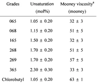
The but yi rubber used in this study, ExxonMobil But yi 065, was kindly supplied by ExxonMobil Chemical, and had an unsaturation level at 1.05-0.20 mol %.1 The Mooney viscosity (ML 1 +8, see Appendix B) at 125 oC was 32
±
3. The halobutyl rubber, ExxonMobil chlorobutyl rubber 1066, had a Mooney viscosity (ML 1+8) of 38±
5 at 125°C and a chlorine content of 1.26±
0.08 wt%. The characteristics of but yI rubber were supplied by ExxonMobil laboratory. The commercial samples were used without further purification.The organic solvents used, including toluene (ca. 98%), hexane (ca. 98%), isooctane (ca. 98%), and heptane (ca. 98%), were obtained from Sigma-Aldrich.
The surfactants Aerosol OT (AOT, 96%, sodium bis(2-ethylhexyl) sulfosuccinate) and NPES-428 (Poly(oxy-l ,2-ethanediyl), alpha-sulfo-omega-(nonylphenoxy)-, sodium salt) were purchased from Sigma-Aldrich. AOT is very hygroscopic and absorbs moisture from air. It was thus recrystallized three times from hot methanol and dried under vacuum.
Cosurfactant can reduce the critical micelle concentration (CMC) in the emulsion.2, 3 Therefore, the emulsion will be more stable with a cosurfactant.4 The
reduction of CMC is more significant with a longer hydrocarbon chain and a higher cosurfactant concentration. J,.5 Short chain a\cohols are directly influencing properties of
the emulsion. Considering the priee, the toxicity, and the impact on the stability of emulsion, isopropanol (ca. 98%) was selected as cosurfactant.
Vulcanizing agents, sulfur and zinc oxide (ZnO, 99.9%), were used as received from Sigma-Aldrich. ZnO was used as an activator in the curing process. The accelerator, tetramethylthiuram disultide (TMTD, 97%), has the following structure.6
2.2. Preparation of samples
2.2.1. Emulsion preparation
The emulsions were prepared at room temperature. The but yi rubber was tirst dissolved in the organic solvent for about 24 hours to make sure that the but yi rubber was dissolved. The surfactant was dissolved in water and the mixture was added into the oil phase containing but yI rubber. The emulsitication was made with a high-speed dispersing and emulsifying apparatus (PowerMax AHS 200 homogenizer) at an agitation speed of 35,000 rpm for 2 minutes.
Many commercial surfactants are sold with different water contents. For example, Poly( oxy-l ,2-ethanediyl), alpha-sulfo-omega-(nonylphenoxy)-, sodium salt (NPES-428) is a surfactant used in hexane but it contains 72 % of water. Before adding the surfactant to but yi rubber solution (but yi rubber with organic solvent), it should be dissolved in water to help mix with the but yI rubber solution. Based on the water contained in the commercial surfactant and quantity of water added in the solution, the amounts ofNPES-428 and water were ca\culated.
2.2.2. Phase diagrams
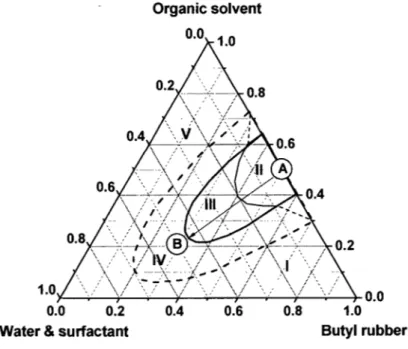
To find the best proportion of ingredients, a ternary phase diagram was determined from the three·component systems. It may be represented as a three· dimensional diagram, more commonly, or as a triangular phase diagram, with each axis representing the content of but yi rubber, the organic solvent, and the water·surfactant mixture (see Figure 2.1).
To obtain a phase diagram for the ternary systems, but yi rubber was first dissolved into organic solvent (point A), followed by the addition of the surfactant mixture. To move from point A to point B, a measured amount of the water-surfactant mixture was added gradually to the solution and the viscosity of the mixture was closely examined after each addition. Along the AB line, the sample may exist as a gel (area Il), a stable emulsion (area 111), or an unstable emulsion (area IV). The phase diagram contains both a stable emulsion area (oil-in-water emulsion) and a gel area (water-in-oil emulsion). The gel area was defined by its high viscosity and the experimental definition of this area is discussed in Section 3.2.6. In a typical experiment, but yi rubber with organic solvent (point A) was placed in a 1 Q-ml test tube, and then the water-surfactant mixture was added gradually (AB line). The solution was mixed for 2 minutes by the use of a homogenizer. After 24 hours, if the sample is still stable (the emulsion is uniform, and there is no phase separation), more water-surfactant may be added (along the AB line in Figure 2.1). Normally, around 0.2 ml of the water-surfactant mixture was added each time in the stable emulsion until an unstable emulsion (area IV) was obtained (with phase separation in 24 hours). In this way, the stable area can be defined in the phase diagram.
Upon the completion of the experiment along the AB line, another starting point with a new composition of the but yi rubber in organic solvent mixture was selected and the same procedure was repeated for the verification of the state of the temary mixture. This was repeated until the entire phase diagram was mapped to define the boundaries of each of the areas as indicated in Figure 2.1.
A large amount of organic solvent in the sample should be avoided, since the major objective of this project is to replace or reduce the amount of organic solvent used. In area 1, the samples cannot be used, because but yi rubber swelled in a small quantity of the organic solvent. In area V, the sample phase is separated when the water-surfactant mixture is added to il. Therefore, the sample in areas 1 and V cannot be considered for this project. In a large portion of the temary phase diagram, gels were obtained at a low content of the water-surfactant mixture. The stability of the sample decreases with an increase in the content of the water-surfactant mixture. The viscosity of the samples in gel area (area II) is too high to make but yI rubber gloves. A stable emulsion is required to make but yI rubber gloves, and the appropriate composition can be found in area III.
Organic solvent
0.0 1.0
1.0Y---r.--r---r--+---'.o'--f-_--+---;'--+ 0.0
0.0 0.8 1.0
Water & surfactant But yi rubber
1 : but yI rubber swelling Il : gel
III: stable emulsion IV: unstable emulsion
V: emulsion with a large amount of organic solvent
( )
Add organic solvent
But yI rubber Point A: solution ______ Addwater ~.I Point B: emulsion surfactant
'---~
Figure 2.1. Scheme of construction for a ternary diagram. The composition of each component is defined by its weight fraction.
2.2.3. Procedure of vulcanization
Vulcanization is the basic process for establishing crosslinks between unsaturated hydrocarbon chains.7 The mixture containing ZnO, sulfur, and TMTD (in a ratio of but yi rubber : ZnO : sulphur : TMTD = 100 : 10 : 2 : 2 (w/w)), was agitated with the
homogenizer. The mixture was heated at 55-60°C on the mold. During the process, ail the vulcanizing agent mixture should not be added in one shot because it is not easy to make the solution homogenous with a large amount of vulcanizing agents. Therefore, it
should be added gradually. In the temary phase diagram, a stable emulsion zone needs to be identified. ZnO was added into the emulsion and mixed for 1 minute. After the addition of the vuJcanizing agents (sulfur and TMTD), the mixture was mixed for an additional 3 minutes by the use of the homogenizer. The temperature of the mixture increased because of the high mixing speed (35,000 rpm). Therefore, the sample should be cooled down to room temperature after mixing to prevent the evaporation of the organic solvent. The suspension, which includes but yi rubber, organic solvent, and water, was crosslinked in the last step. The mixture was poured onto an aluminum plate to make the film, heated at 55-60°C for 5 to 10 minutes for crosslinking. Ail the organic sol vents and water were evaporated during the vulcanization process.
2.3. Instruments and measurements
2.3.1. Viscosity
ln these experiments, the plate geometry was used. The cone-and-plate and parallel cone-and-plate measurements are most often used for highly viscous pas te gels and concentrated suspensions.8 The parallel plate geometry can be considered as a simplified version of the cone-and-plate having an angle ofoo.9 If the sample has a very high viscosity, the parallel plate geometry is preferred, because it is easy to measure if the sample is constrained in the narrow space between the two surfaces. For our study, the viscosity of the samples (ca. 10 Pa.s) was not very high. Therefore, the cone-and-plate geometry was a good choice.
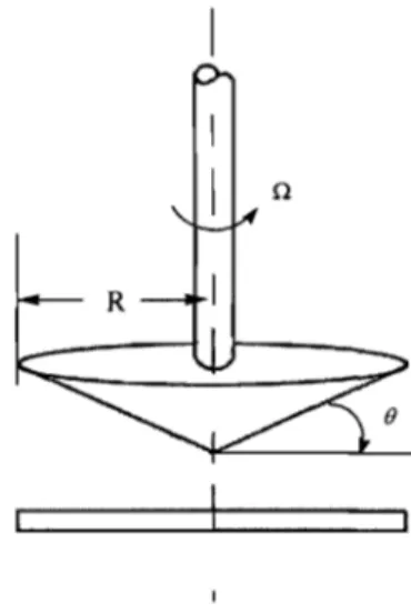
The viscosity was measured with an AR2000 rheometer from TA Instruments equipped with a cone-and-plate geometry. The cone-and-plate geometry is used frequently for measuring the viscosity of emulsions.9 The cone-and-plate geometry consists of an inverted cone in near contact with a lower plate. The cone used has an angle of 1 °59' 18" (Figure 2.2). The upper part rotates while the bottom is fixed stator and allows proper control of heating or cooling of the sample on the plate.
Figure 2.2. Schematic diagram of the cone-and-plate geometry for the
rotational rheometer
The range of the shear rate is from 0.01 to 100 S·l. The shear rate is fixed during making but yi rubber gloves, because the dipping speed of the mold is not changing. A rational dipping speed can be selected from this range. Steady state flow data was recorded with an increase of the applied torque followed by a decrease (the viscosity was measured with a decreasing shear rate). The torque was imposed using a logarithmic ramp in order to decrease the initial acceleration and the effect due to
instrument inertia. Experiments close to the boundary zone between the "gel area" and the "emulsion area" were repeated 3-4 times under the same conditions. The distance between the cone and the plate was 600 IJm, which determined the amount of sam pie to be used. A batch of 0.75 ml of sample for each set of measurements was placed on the plate. During ail experiments, the cone-and-plate part was always covered with a solvent trap to prevent the evaporation of the solvent.
2.3.2. Dynamic mechanical analysis (DMA)
DMA measurements were done with a DMA 2980 instrument from TA Instruments. The test sample was fixed on a tension film clamp. The samples were measured at an operating frequency of 1 Hz and a heating rate of 2°C/min from -80 to 40°C. The sam pie was prepared by placing the mixture of stable emulsion and vulcanizing agents on the aluminium plate and heating at 60°C. The polymer was vulcanized in the form of film (thickness 0.2 mm) after 8-10 minutes.
2.3.3. Fourier transform infrared {FT IR) spectroscopy
FTIR spectra were recorded before and after vulcanization on a Varian 3100 FTIR spectrometer from Varian equipped with a mercury cadmium telluride (MCT) photodiode detector. A resolution of 4 cm·) was chosen and 128 scans were accumulated.1O The spectra were recorded at room temperature and at 90°C. For FTIR analysis, the membrane samples were prepared by drying the stable emulsion on a aluminum plate at room temperature.
2.3.4. Nuclear magnetic resonance (NMR) spectroscopy
The 1 H NMR spectra of but yi rubber and chlorobutyl rubber were recorded on a
Bruker AMX~400 spectrometer operating at 400.13 MHz at room temperature. But yi rubber was dissolved in deuterated chloroform (from Sigma-Aldrich) and at a concentration of 1-2 %wt.
References
1. Binks, B. P.; Cho, W. G.; Fletcher, P. D. 1.; Petsev, D. N., Stability of oil-in-water emulsions in a low interfacial tension system. Langmuir 2000, 16, (3), 1025-1034. 2. Chennamsetty, N.; Bock, H.; Scanu, L. F.; Siperstein, F. R.; Gubbins, K. E., Cosurfactant and cosolvent effects on surfactant self-assembly in supercritical carbon dioxide. The journal of chemical physics 2005, 122.
3. Jin, D.; Jiang, X.; Jing, X.; Ou, Z., Effects of concentration, head group, and structure of surfactants on the degradation of phenanthrene. Journal of Hazardous Materials 2007, 144,215-221.
4. Tamilvanan, S., Oil-in-water lipid emulsions: implications for parenteral and ocular delivering systems. Progress in Lipid Research 2004, 43, (6), 489-533. 5. Lopez, F.; Cinelli, G.; Ambrosone, L.; Colafemmina, G.; Ceglie, A.; Palazzo, G.,
Role of the cosurfactant in water-in-oil microemulsion: interfacial properties tune the enzymatic activity of lipase. Col/oids and Surfaces a-Physicochemical and Engineering Aspects 2004, 237, (1-3),49-59.
6. Gonzalez, L.; Rodriguez, A.; Del Campo, A.; Marcos-Fernandez, A., Crosslink reaction of natural rubber with thiuram sulphur donors in the presence of a thiuram monosulfide. Journal of Applied Polymer Science 2002,85, (3), 491-499. 7. Aprem, A. S.; Joseph, K.; Thomas, S., Recent developments in crosslinking of
elastomers. Rubber Chemistry and Technology 2005, 78, (3), 458-488.
8. Ferraris, C. F., Measurement of the Rheological Properties of High Perfonnance Concrete: State of the Art Report. Journal of Research of the National Institute of Standards and Technology 1999, 104, (5), 461-479.
9. Chung, C. A.; Tzou, M. R.; Ho, R. W., Oscillatory tlow in a cone-and-plate bioreactor. Journal of Biomechanical Engineering-Transactions of the Asme
2005,127, (4), 601-610.
10. Hrnjak-Murgic, Z.; Jelencic, J., Change of network structure of natural rubber vulcanizate with thermal aging. Macromolecular Materials and Engineering