HAL Id: hal-02309690
https://hal-cstb.archives-ouvertes.fr/hal-02309690
Submitted on 9 Oct 2019HAL is a multi-disciplinary open access
archive for the deposit and dissemination of sci-entific research documents, whether they are pub-lished or not. The documents may come from teaching and research institutions in France or abroad, or from public or private research centers.
L’archive ouverte pluridisciplinaire HAL, est destinée au dépôt et à la diffusion de documents scientifiques de niveau recherche, publiés ou non, émanant des établissements d’enseignement et de recherche français ou étrangers, des laboratoires publics ou privés.
Olivier Flamand, Jean-Christophe Thomas
To cite this version:
Olivier Flamand, Jean-Christophe Thomas. Inflatable walls for wind tunnels. 7th European-African Conference on Wind Engineering (EACWE 2017), Jul 2017, Liège, Belgium. �hal-02309690�
1
INFLATABLE WALLS FOR WIND TUNNELS
Olivier FLAMAND CSTB – France
Jean-Christophe THOMAS
GeM, institut de Recherche en Génie Civil et Mécanique Université de Nantes, UMR CNRS 6583
Introduction
Wind tunnels are usually designed for a prerequisite purpose. Wind tunnels for aeronautical studies aim at reproducing very low turbulence flow at high speed, what they attain through a settling chamber and funnelling effect with a contraction ratio of the section by 8 to more, BLWT are designed for making a boundary layer grow, what means a long flat floor upstream the model and industrial wind tunnel are designed with a continuous flat floor allowing forklifts and other handling vehicles to travel inside. It is therefore difficult to change the initial destination of a wind tunnel, pulling down walls and rebuilding is costly. In order to overcome this issue, an innovative device has been developed for the Jules Verne large climatic wind tunnel, with the aim to modulate its section, opening it to new markets. This device allows a fast and cheap adaptation of the size and shape of the wind tunnel section. Experience of the wind tunnel team with inflatable structures, initially related to modelling of mechanical behaviour of standalone structures under wind loads , was used for taking the challenge of the design, dimensioning and validation of new devices, to be used for changing the shape of the existing wind tunnel.
ORIGINAL WIND TUNNEL
The dynamic loop of the Jules Verne climatic wind tunnel was built more than 20 years ago as very stiff reinforced concrete structure [1]. It lies inside a rectangle 85m long and 55m wide. Its floor is fully flat for letting forklifts circulate and is able to bear heavy loads (2 tons/square meter). It is made of 3 successive testing chambers 15x10m, 6x5m and 8x8m, each one being specialized in a particular kind of testing. The evolution of the shape from one testing chamber to the following one is done by converging or diverging walls and ceiling with a maximum slope of 7°, in order to avoid the flow detach from the walls.
The wind tunnel is powered with six fans, rotating at constant speed with blade pitch adjustable, each connected to an asynchronous electric motor of 520 kW. Because the blade pitch can be adjusted very quickly, it is possible to reproduce bursts. The maximum speed is 75 m/s.
Considering today’s needs, it is assumed that some tests performed in this wind tunnel could be achieved more efficiently in reduced size section. For instance the 15x10m section could be reduced in height to provide a 15m wide x 4m high section suitable for large aeroelastic bridge models. It is also planned to reduce the width of this 15x10m large section to a narrower section, 3m wide x 10m high, for testing lighting poles. This reflexion around section change is part of a larger project consisting in an improvement of the wind tunnel shape by changing one part of the circuit.
2
Figure 1: shape of the existing Jules Verne wind tunnel
Figure 2: improvement of the shape of the Jules Verne wind tunnel, going to Jules Verne 2.0 project
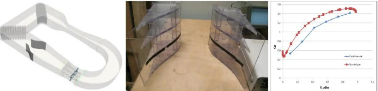
These changes in the size and shape of the test section following the propellers have been checked by CFD modelling and by skin pressure and PIV measurements inside two reduced size models, at a scale 1/10 and 1/36. The shape of the converging walls was first improved in terms of efficiency, avoiding detached flow along the walls and reducing losses in the closed loop circuit, in the sake of reducing the power consumption of the facility.
Loads applied on these converging walls were measured in wind tunnel by pressure taps and calculated in the CFD modelling from the calculated pressures. Both approaches converged and gave a first evaluation of the loads these walls will have to withstand, in order to help in designing these structures.
Figure 3: numerical and experimental approach of the convergent for a narrower section
Among other technical solutions it was considered to design the convergent with inflatable structures.
3
WHY AN INFLATABLE STRUCTURE?
The wind tunnel team had some occasions in the recent past to test inflatable structures in the high speed section and was favourably impressed by the structural performances of such lightweight items. These tests, achieved in the scope of a PhD thesis [1], were also an occasion to collaborate with team TRUST of the laboratory GeM, at Nantes University, which is specialized in the studies of inflatable structures, usually conducting analytical studies, finite element simulations and experiments on such inflatable structures.
Using the internal air pressure inside beams made of light coated fabrics for conferring a relevant stiffness to a building is not really a modern concept but is clearly underused. It is mostly applied for temporary structures, because it is easy to transport and the erection of the building is self propelled. No foundation is required, no crane or boom is needed, risk of accident to work is reduced at its minimum. An emblematic example of inflatable building is the mobile hangar that protects Solar Impulse airplane (figure 4). It should be noted that if foundations are not necessary, anchorages must be ensured in strong winds. One great advantages of these structure is that when the event ends, the temporary building is easily and quickly folded with a minimal impact on environment.
Figure 4: solar Impulse mobile hangar
Adapting the shape of the wind tunnel cross section to a narrower of a lower ceiling test chamber can be considered as a temporary evolution of the inner shape of the facility. The testing period usually last from one day to some weeks, after what the wind tunnel must come back to its initial configuration and the temporary wall dismounted and stored.
One of the major benefit from inflatable structure it the ratio of its size in use to its size when stored. Because the fabrics is thin and easy to fold, when deflated an inflatable structure is very easy to pack away and can potentially be kept inside the wind tunnel, when solid temporary structures are the same volume when they are unemployed than when they are in use and require an outside solution for their storage.
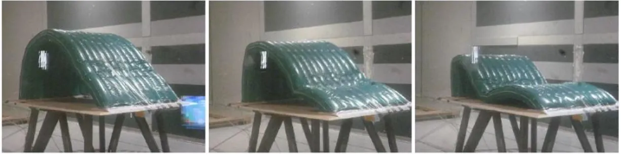
Figure 5: experiments with inflated structures inside the Jules Verne wind tunnel, studying its collapsing with wind
They must be some drawbacks for such a structure, explaining why its use is not so common. The design team made a short list of them :
4 - Fragility of the fabrics. Is it possible a piece of hard material flies in wind and cut the membrane, making the temporary wall collapse during the experience? Of course this potential occurrence exists, but consequences would not be dramatic. Because the wind tunnel original walls are still in place, disappearance of one temporary wall will not change substantially the behaviour of the whole building. Consequences on the propellers themselves are of limited extend. The cost of fixing the tear is very limited. Repairing an inflatable structure can be achieved on site, quickly and easily.
- Additional cost for the powering of the blower that is used for pressurizing the inflated structure? Compared to the wind tunnel power, this is peanuts. The blower can be, at its maximum power, needing 1kW, when the wind tunnel needs 3 000 kW.
- Risk of explosion and resulting blast? Actually, inside pressure of inflated structures is quite low and this is not an issue.
- Will an inflated wall stay rigid enough for resisting to the pressures applied on it by the wind? This is one of the questions we aimed at answering.
- Is there a risk that the inflated structure “beats” with wind and that this oscillation impacts the quality of the flow? This is also a question that this study was done for addressing.
Experience of the wind tunnel team with inflatable structures, initially related to modelling of mechanical behaviour of standalone structures under wind loads, was used for taking the challenge of the design, dimensioning and validation of new devices, to be used for changing the shape of the existing wind tunnel.
MODELLING OF AN INFLATABLE STRUCTURE Construction of Inflatable Structures
Construction material:
Inflatable structures are generally made of flexible materials, which are relied together by different types of lying: gluing, sewing, or high frequency welding. In the most common applications of inflatables, these materials are of two types: films such as those used on inflatable cushions use in architecture, or textiles made of warp and weft yarns, interconnected by a coating which makes it possible to ensure the water or air tightness; They can be covered with different protective layers depending on the effects, properties or functions expected (UV protection, special roughness, etc.).
Figure 6: structure of a coated fabric
Stiffness of structure:
Textiles have almost zero flexural rigidity. The stiffness of the structures is ensured by a pre-tensioning of the fabrics, which may be done with of a mechanical device (by cables, for example, for tensioned membranes like the one used for roofs), or by a pneumatic device. This pretension is bi-axial in almost all cases. The state of pretension is paramount, since it ensures the integrity of the structure. One of the key criteria for the behaviour of textiles is the appearance of wrinkles. This corresponds to a local buckling, and is one of the key points of the dimensioning of these structures.
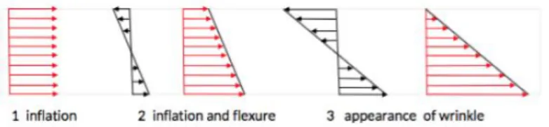
5 The family of pneumatic structures is divided into three groups: mono-membrane structures (only one membrane, simply supported by air), air-inflated structures, and hybrid structures. We are interested in this study to air-inflated structures. It is necessary to distinguish between the inflation step and the in-service step. The inflation step makes it possible to tension the fabric, and to obtain the initial geometry of the structure before deformation dues to other external loads. To understand the principle of operation of these specific structures, let’s consider one of its simplest example: an inflatable beam (see figure 7). During the pre-tensioning step, the constituent material is subjected to longitudinal stresses and axial stresses. The figure presents the evolution of the axial stresses. The inflation inducts a uniform distribution of stresses inside the section of the beam. If the beam is submitted to bending loads, for example for a bi-applied beam, the flexural stresses (in black on figure) are superimposed on the pretension stresses (in red). This causes an increase in the axial stress in the lower part of this beam, and decrease in the stress in the upper part. Thus, by increasing the bending load, it is possible to cancel the axial stress, which causes the occurrence of a wrinkle. Note that the apparition of wrinkle is not crucial for the behaviour of the structure, since the beam can still withstand higher loads. But it can be considered as a design criterion often for aesthetic or psychological considerations. In the case where it is desired to use an inflatable structure to modify an air flow in a wind tunnel, it is necessary to ascertain the surface condition of the structure used, and this criterion of nonappearance of a wrinkle will also be important.
Figure 7: Stresses in a cross-section
Designing inflatable structures
What are the key points of the design?
This depends on the use of the structure. The criteria are generally based on quantification of the state of stresses in the material and on the displacements. There are maximal values of the state of constraints not to be exceeded with respect to the resistance limits of the fabrics and the connections, and the minimum values which avoids occurrence of a wrinkle, or a collapse. The second type of criterion concerns the deformations of the structure, and is based on its maximum displacements. It is required, for example, that the maximum displacement of a point of the structure is less than a predefined percentage of a dimension of the structure (width, height, length for example).
In some specific cases, attention will also be paid to the vibrations of the structures, to see if there are risks of resonance or not.
For the considered convergent, the proposed design criteria are:
- Positive tension state in the fabrics (no wrinkle appearance that can alter the flow) - Tension not exceeding the strength of the connections and fabrics
- Minimal movements of the upper skin of the convergent - Avoid vibration modes.
Modeling
For inflatable structures, analytical or numerical studies can be carried out. There are analytical formulas for inflatable beams, but for more complex structures such as the convergent, or inflatable buildings, finite element software can be used. For this purpose, the structure is modelled by considering the material as a membrane, since the thickness of the fabric is of a very small dimension with respect to the other dimensions, and since there is no flexural rigidity of the material when it is
6 not pre-stressed. The elements chosen for the numerical model are in our case membranes elements of type T6 or Q8.
Since these elements have no flexural rigidity, it is necessary to perform a fictitious pretension at the first increment, which is cancelled after the first increment has passed.
Concerning the materials, there is a great amount of work currently in the scientific community to define which model to use for the textile materials used in the membrane structures. The simplest model is the isotropic material (same properties in all directions), for which one will define a Young's modulus and a shear modulus. This model can be used for films for example, or for pre-sizing steps. To get closer to the physical reality of the material, an orthotropic model is preferred, considering the warp and weft directions, aligning them with the directions of orthotropy of the material. In this case, it is necessary to define two Young's moduli in the two orthotropy directions, a Poisson coefficient, and a shear modulus. This model is widely used for the design of textile structures, even if it does not fully account for the non-linearities observed during bi-axial tensile experiments in laboratories, nor for the viscoelasticity inherent of this type of materials. For the inflatable convergent, both models will be used.
The proposed calculation is a calculation in large transformations, using the total Lagrangian formulation. Thus, the second-order terms are taken into account in the deformation tensor, and the calculation is brought back to the initial configuration (non-pressurized). This means that the material coefficients used for the simulations are the coefficients corresponding to the natural state of the fabric, ie for the non-pressurized structure.
The pressure is considered as an external load applied on the membrane. It is a follower force which means that the forces dues to the inside pressure remains always orthogonal to the membrane. External loading (here, wind loading) can be introduced in the form of point forces, or load densities. The boundary conditions are introduced at the nodes, and allow to model the connections of the structure with its environment.
Calculations and expected results
The simulations proposed are simulations showing the first results concerning the mesh of a structure similar to the convergent. We use for this a code developed in the GeM laboratory, which was originally planned for simpler structures than the one we are interested in here, and whose computational capabilities will soon be increased.
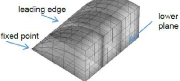
Figure 8 shows the mesh that has been used for this example: it is a structure of the same type that the one used in the wind tunnel, made of 6 partitions (against 10 for the convergent). For symmetry reasons, only half the structure is studied, by imposing that the middle partition stays in a vertical plane. Concerning the boundary conditions, it is considered that the nodes of the lower part remain in a plane, that the points of the leading edge remain on a line, and that a point of this line is fixed.
Figure 8: mesh and boundary conditions
Resulting inflation:
Figure 9 presents the results of the inflation. This is an important step of the design because it allows to pre-define the final shape of the structure. In fact, this corresponds to a step usually used in the design of membrane structures: form-finding. What is the shape in the natural configurations (without
7 any pressure inside) that will allow to get the shape which is required for the specific function for which it has been built?
Figure 9: results of the inflation
At the end of this step, it is possible to:
- Verify the geometry of the inflated structure - Calculate the stresses at the end of the inflation
- Apply external loads and calculate the displacements and the stresses - Calculate the vibration modes.
EXPERIMENTAL SETUP
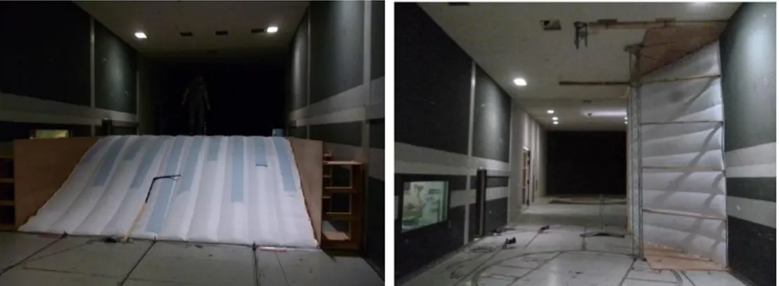
A model of an inflatable convergent was built at a scale 1/3 and tested in wind tunnel up to high wind speed. This model was equipped with pressure sensors glued on its surface. It was tested in a horizontal position and in a vertical arrangement in the high speed section of the wind tunnel which is 6m wide and 5m high. The model was 5m wide in order to fit vertically inside the test section and side spacers of 0.5m were added for the tests in horizontal position (figure 10).
Figure 10: Model of inflatable convergent in the high speed section of the wind tunnel, in horizontal and vertical location
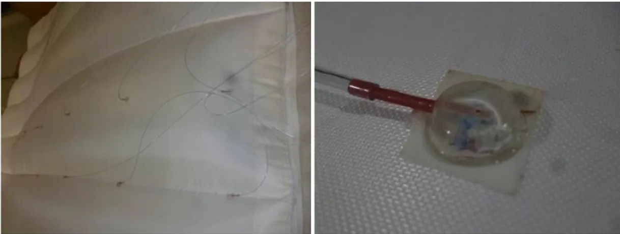
The actual shape of the convergent was checked in place at rest by manual measurement. Three rows of 20 pressure taps were located at the surface of the convergent model, all connected to two pressure scanners of 32 channels. The inside pressure was measured too and was varied by acting on the blower. Static pressure was measured by a Pitot tube located in the same section as the model.
8
Figure 12: Arrangement of pressure taps on the fabrics and detailed view of one pressure tap
Measurements made for three levels of inside pressure give very similar results, what means the shape of the convergent does not really depend on this internal pressure, even at high wind speed.
9 These have been compared to the pressure field along the convergent calculated by the CFD simulation and are very close to it.
Wind speed gradient have been measured upon the convergent model and compared to the CFD model too.
Both kinds of measurement serve for checking the RANS CFD model of the reduced scale convergent inside the wind tunnel, with the aim to use the same modelization for the design of the final convergent at full scale, one of the most important feature being the loads transmitted by the inflated structure to the walls of the wind tunnel.
DYNAMIC BEHAVIOUR OF THE CONVERGENT WITH WIND
The major unknown in the final convergent design is the dynamic behaviour of the inflated fabrics. Will it rattle or throb in the wind? The stability of the inflated structure at various wind speeds is a fluid-structure interaction problem which can be solved by a complex modelization that was not affordable in this project. This is the reason why measurements in wind tunnel have been used with FE modelling of the inflated cushion for a simplified checking of mode shapes frequencies.
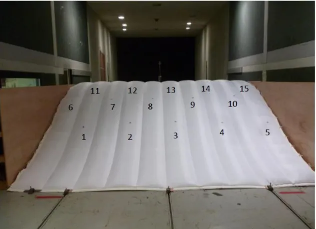
The 1/3 model of the convergent was equipped with reflective tape targets in 15 locations, for the measurement of the structure vibration with wind by a pulsed infrared tracking system.
This measurement system is composed with 6 CCD cameras looking at the structure from the ceiling and giving the displacement of each target, at a rate of 400 data per second, in 3D and with a precision better than 1mm.
Figure 14: Location of displacement measurement targets on the fabrics.
The time history of the displacement at each target location was analysed in the frequency domain and the PSD’s show vibrations at 15 Hz and 18 Hz for an internal pressure of 650Pa, to be compared with calculation results.
10
Figure 15: time history of the vertical displacement measured in three locations on the convergent model.
Figure 16: PSD of vertical displacement at locations P5, P8 and P11
CONCLUSION
Design and use in a large wind tunnel of inflatable convergent seems an innovative process. It is under way for the Jules Verne climatic wind tunnel as a collaborative work.
REFERENCES
[1] J. Gandemer, 1992, "La soufflerie climatique “Jules Verne” ", Journal of Wind Engineering and Industrial Aerodynamics, volume 41, Issues 1–3, October 1992, Pages 43-54
[2] A.Bloch, 2016, "Expérimentation et modélisation du comportement des structures gonflables sous chargement aérodynamique aux états-limites", PHD , Université Nantes, Angers Le Mans, France [3] A. Bloch, M. Francois, J.-C. Thomas, O. Flamand, 2014, "Monitoring of Inflatable Structures by Using Virtual Image Correlation", 7th European Workshop on Structural Health- Monitoring – WSHM, hal-01020416
[4] A. Bloch, J.-C. Thomas, O. Flamand, 2014, "Development of similitude law for inflatable structure under wind loading", 14th International Conference on Wind engineering, ICWE14, Porto Alegre, Brésil [5] Q.-T. Nguyen, J-C. Thomas, A. Le van, 2015, "Inflation and bending of an orthotropic inflatable beam", Thin-Walled Structures, Vol. 88, 129-144.